Energy and Power Engineering
Vol. 4 No. 2 (2012) , Article ID: 18031 , 4 pages DOI:10.4236/epe.2012.42013
Optimal DG Placement in Distribution Networks Using Intelligent Systems
1Department of Electrical Engineering, Takestan Branch, Islamic Azad University, Takestan, Iran
2Department of Electrical Engineering, Hidaj Branch, Islamic Azad University, Hidaj, Iran
3Department of Electrical Engineering, Qazvin Branch, Islamic Azad University, Qazvin, Iran
Email: {ali.aref89, m.davoodi1}@yahoo.com, Mohsen.davoudi@polimi.it, farzad.razavi@qiau.ac.ir
Received December 21, 2011; revised January 22, 2012; accepted February 4, 2012
Keywords: Distributed Generation (DG); Distribution Network; Optimization; Genetic Algorithm
ABSTRACT
Distributed Generation (DG) unlike centralized electrical generation aims to generate electrical energy on small scale as near as possible to the load centers, interchanging electric power with the network. Moreover, DGs influence distribution system parameters such as reliability, loss reduction and efficiency while they are highly dependent on their situation in the distribution network. This paper focuses on optimal placement and estimation of DG capacity for installation and takes more number of significant parameters into account compare to the previous studies which consider just a few parameters for their optimization algorithms. Using a proposed optimal Genetic Algorithm, a destination function that includes the cost parameters (such as loss reduction, fuel price, etc.) has been optimized. This method is also capable of changing the weights of each cost parameter in the destination function of the Genetic Algorithm and the matrix of coefficients in the DIGSILENT environment. It has been applied and simulated on a sample IEEE 13-bus network. The obtained results show that any change in the weight of each parameter in the destination function of the Genetic Algorithm and in the matrix of coefficients leads to a meaningful change in the location and capacity of the prospective DG in the distribution network.
1. Introduction
Distributed generation (DG) is defined as small generation units installed in distribution systems. It is predicted that DG would have a share of about 20% of new generating units being on lined [1]. DG applications are growing due to environmental and economic issues, technological improvements, and privatization of power systems. DG application, however, has positive and negative side effects for public industries and consumers [2].
Generally, DG effects in distribution network depend on several factors such as the DG place, technology issues, capacity and the way it operates in the network. DG can significantly increase reliability, reduce losses and save energy while is cost effective, though it suffers from some disadvantages because of the isolated power quality functioning, and voltage control problems. Generally, planners assess DG functioning in two respects: costs and benefits. Cost is one of the most important factors that should be considered regarding DG application [3-4].
There are so many DG placement methods in hand though each of these methods only focuses on some parameters. The optimal DG placement defined in [5] takes reliability, loss reduction, and load prediction into account while it fails to account for other parameters such as productivity, cost effectiveness, and type of DG. The optimal DG placement defined in [6] takes productivity, cost effectiveness, loss reduction, and reliability and DG type into account and fails to consider other parameters. Reference [7] only focuses on three parameters: DG cost, loss reduction and reliability. Also reference [8] defines its optimal DG placement method taking DG capacity, cost effectiveness and loss reduction into account. In addition, reference [9] defines its optimal placement method taking stability, loss reduction and productivity into account. In [10] optimal DG placement method takes loss reduction and load prediction into account. These fail to consider all aspects and parameters involving optimal DG placement. The present study is an attempt to define optimal DG placement by taking all pertinent parameters (loss reduction, voltage profile improvement, effects on environment, fuel price, load prediction cost) into account and since DG type is selected based on DG location based on its installation capacity, parameters specific to the location must be determined.
The organization of the remainder of this paper is as follows. The statement of the problem is presented in Section 2. Section 3 describes the implementation of the proposed method on a sample IEEE 13-bus distribution system. Finally, simulation network, and simulation results are shown in Section 4, 5 and 6 respectively followed by conclusions.
2. Statement of the Problem
Since the use of distributed sources is highly dependent on climatic and regional conditions, various DG technologies have been developed. These technologies are divided into three general categories [11-12]:
• Technologies working on fossil fuels such as combustion engines, micro turbines, and fuel batteries.
• Technologies working on new sources of energy such as wind turbines, solar cells, wave energy, geothermal and biomass.
• Technologies working on saving energy such as batteries, fly wheels, Superconducting Magnetic Energy Storage (SCMES), capacitors, Condensed Air Energy Storage (CAES) and Hydro Pumps.
Because of the traditional structure of power networks and lack of an active source of generation in the distribution system, as the installed capacity of generating sources increase, it becomes important to study the effects of these sources when they are working in tandem with electrical networks. The major effects of the distributed generation sources at the time of installment and exploitation include:
• Voltage profile changes along the network based on production capacity of the units and based on consumption load. This can specially be observed in radial feeders.
• Network losses change as a function of consumed load and production.
• Transit currents and voltages appear in the network as the instant distributed generation sources connect or disconnect.
• Quality of power and capability of the network protection system change.
• Nowadays, because of the changes made in the power system structures for optimization purposes as well as the modernization of these structures, distributed generation sources are inevitably becomes important that in some countries they are considered as supplementary power supply systems. On the other hand, to satisfy the increasing power demand, huge power plants have to be constructed. There are, however, some obstacles such as finding a proper place for establishment, costs incurred due to the transfer of the electricity to places far away from the power plants, and the long interval between decision-making and actual exploitation. Hence, distributed generation is now of great importance to development planners because they can be connected to the network easily and close to the load. Distributed generation is obviously a new attraction for power industry, commercial and regulating systems [13].
In examining and identifying the technologies of DG sources and their effects on the distribution network, one should bear in mind that the technology being applied must be capable of producing the required power in order to enjoy the benefits of DG sources in the distribution network. Also, optimal DG placement should be selected taking the conditions and status of each bus in the network [14].
3. The Proposed Method
In the present study, for the above mentioned purpose, a destination function should be defined that includes all of the proposed parameters. The destination function, which is going to be minimized in this study and includes loss, voltage profile, environmental costs, fuel price and cost of load prediction for each bus, is as follows:
 (1)
(1)
where  is the cost of loss in all lines,
  is the cost voltage profile improvement,
  is the cost incurred due to effects on environment,
  is the cost of the fuel used by DG sources,
  is the cost of load prediction for each bus and for the buses in which the load amount is not predictable. DGs must save energy and this requirement incurs costs, which have been taken into account in the above function. To define the destination function in (1), we have to make all parameters per unit to make them additive, this was accomplished by applying “
 ” coefficients (
 -
- ). To calculate the cost of loss, first load flow is carried out in DIGSILENT software and then the results are used to calculate the losses and ultimately they are multiplied by the loss price. To calculate the cost of voltage profile improvement for each bus, the voltage difference for each bus is calculated before and after DG installment and the difference figure is multiplied by the cost of voltage profile improvement. To calculate pollution reduction cost using DG sources, the present study takes into account the variability of these coefficients for each bus depending on the type of the DG technology, and the cost incurred due to pollution which is calculated [15].
It is noteworthy that each of the coefficients of the environmental pollutions effects, fuel and load prediction have been defined in DIGSILENT environment in the form of a matrix where these parameters are variable of each bus. Such values are shown in Tables 1-12. This paper has two major goals: 1) Improvement of voltage profile 2) Loss reduction. There are also some limitations based on which the destination function should be defined [16]:
1) 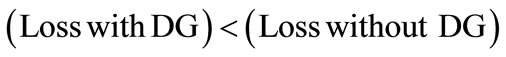
2) 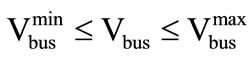
According to the first limitation the loss reduces when DG exists. Also, second limitation states that the authorized voltage of a certain bus depends on the minimum and maximum voltages of the bus.
4. Simulation Network
In the proposed work, in order to observe and compare the results with those of the specified destination function, an IEEE 13-bus distribution network has been selected as a sample. It should be noted that the specified destination function can be generalized to be used for all distribution networks with any number of buses. Moreover, the optimization algorithm of the destination function is a Genetic Algorithm whose chromosomes are as analogous to the variables of location and capacity of DG. The single line diagram of the network is illustrated in Figure 1.
According to Figure 1, 13-bus network contains two feeding sources in buses 1 and 6. Tables 1 and 2 show the data on the lines and buses [17].
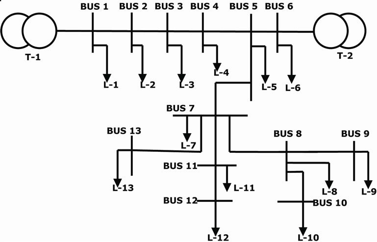
Figure 1. Single line diagram for IEEE 13-bus distribution network.
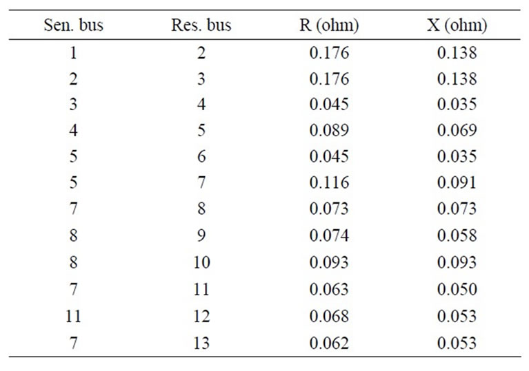
Table 1. Data on the lines.
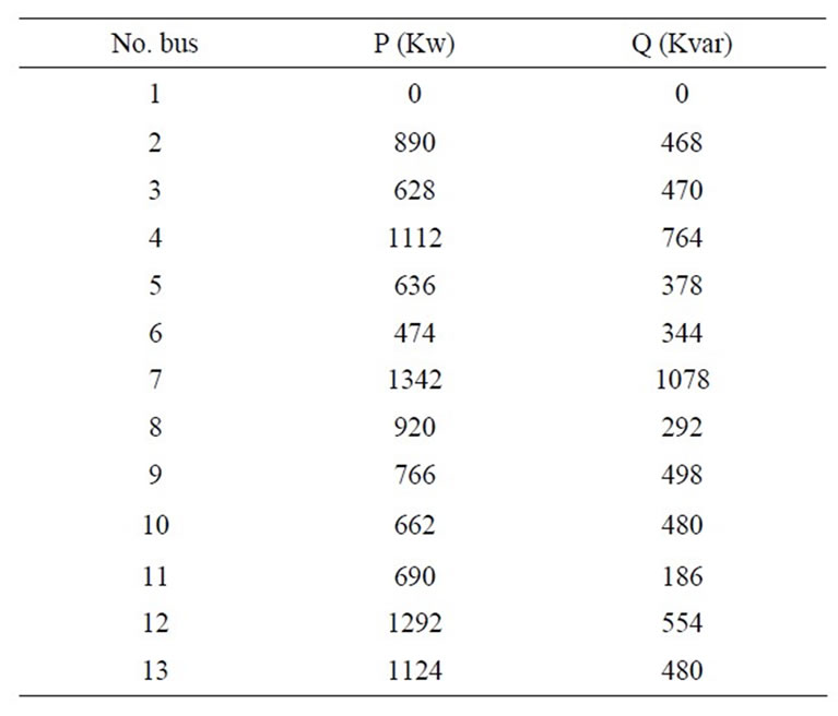
Table 2. Data on the buses.
5. Simulation
This study aims to optimize the placement of DG and assess DG capacity using weight coefficients for various parameters independently taking cost into account. The coefficients of the first case shown in Table 3 include loss-reduction parameters like voltage profiles, environmental factors, fuel price and load prediction in the destination function of the Genetic Algorithm shown by ( -
- ) in the destination function. However, other coefficients shown in Table 4 are related to the weight of parameters for the effects of environmental factors, fuel price, load prediction which are defined in an input matrix for the simulation software. In this case, since parameters related to loss reduction and voltage profile are calculated automatically, the coefficients of these parameters are not considered in the input matrix for the software. Thus, generally, parameters for any network have two conditions of weight coefficients with any number of buses. This has been achieved using genetic algorithm optimization in DIGSILENT environment. The parameter changes are illustrated because they are variable in each bus. Optimization is carried out with Genetic Algorithm using a cost function. For this purpose, changes in the coefficients of the parameters are specified due to their variability in each bus. Optimization of the destination function has been carried out using a Genetic Algorithm.
To assess the effect of loss reduction, voltage profile coefficient, environmental coefficient, fuel price and load prediction cost on the program, the program output was examined under two conditions (1), (2). For this purpose, different coefficients were applied to destination function parameters. Table 3 presents coefficients applied to parameters under the first condition, where parameters may vary depending on the place of the bus.
In addition, Table 4 presents an example of the weight of each parameter such as environmental pollution, fuel price and load prediction under the first condition. Table 5 presents program outputs regarding to the optimal capacity and placement of the prospective DG.
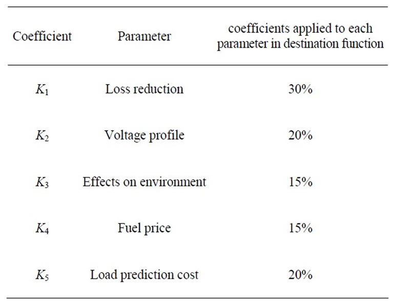
Table 3. Coefficients applied to the parameters under the first (1) condition.
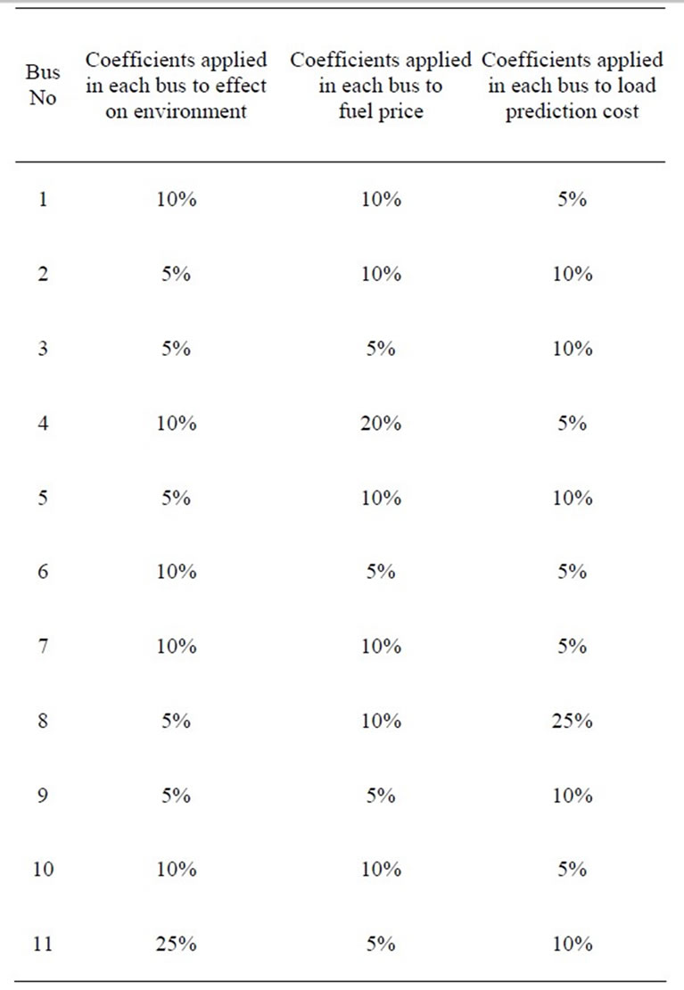
Table 4. An example of the weights of each parameter.
6. Simulation Result
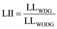
The proposed method has been developed in DIGSILEN and MATLAB environments. The optimization algorithm in the present study is a Genetic Algorithm included in MATLAB, version 7 or higher applicable directly. Table 5 presents the candidate position for DG installation in a 13-bus network as well as the capacity of optimal DG in terms of KW using LII and VPII indexes.
Also, in the above outlet, line loss reduction index is defined by [18-19]:
 (2)
(2)
where  and
and  are the losses incurred with and without DG presence, respectively. This indicator can have the following implications under the following three conditions:
• LII < 1: DG reduces loss
• LII = 1: DG is not effective
• LII > 1: DG increases loss Furthermore in Table 5, VPII indicates voltage profile improvement and shows the effect of DG placement on the voltage profile which is defined as follows [14-15]:
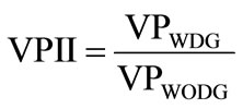 (3)
(3)
where  and
and  are the voltage profiles with and without DG presence, respectively, and can be interpreted as follows under the following conditions:
• VPII < 1: DG has a negative effect on network voltage
• VPII = 1: DG is not effective
• VPII > 1: DG has a positive effect on network voltage
To observe the effect of each parameter including environmental pollution, fuel price, and load prediction cost, we changed the coefficients applied to each parameter in each bus in the form of a matrix. Table 6 presents the weight of another example of parameters such as environmental pollution, fuel price and load prediction, under condition of Table 3. In addition, Table 7 presents program outputs regarding to optimal capacity and placement of DG.
To test the program results under a different condition, we change all coefficients applied to the parameters of the destination function. Table 8 presents coefficients applied to parameters under different condition of Table 3. In addition, Table 9 presents the weight of parameters such as environmental pollution, fuel price and load prediction, under the same condition of Table 8. Also, Table 10 presents program output with regard to the optimal capacity and placement of DG.
To observe the effect of each parameter including environmental pollution, fuel price and load prediction cost, we changed again the coefficients applied to each parameter in each bus. Table 11 presents the weight of another example of parameters such as environmental pollution, fuel price and load prediction under the same conditions of Table 8. Finally, Table 12 presents program outputs with regard to the optimal capacity and placement of DG.
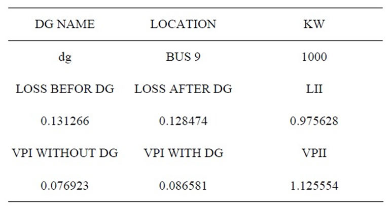
Table 5. The program outputs.
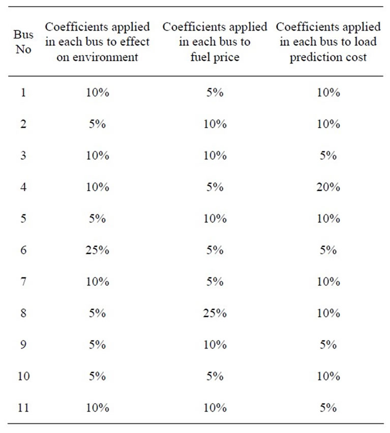
Table 6. An example of the weights of each parameter.
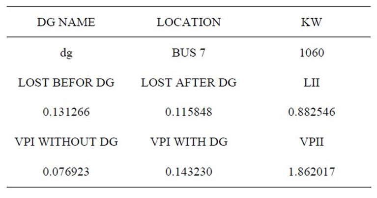
Table 7. The program outputs.
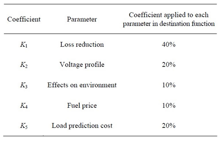
Table 8. Coefficients applied to the parameters under the second (2) condition.
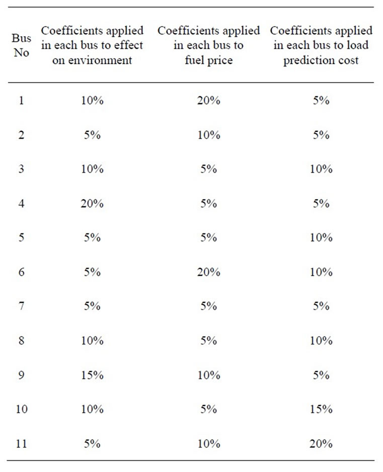
Table 9. An example of the weights of each parameter.
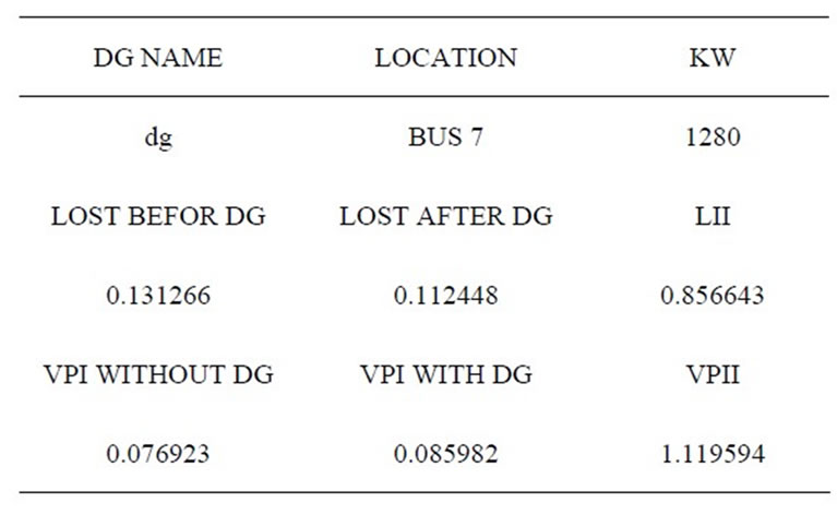
Table 10. The program outputs.
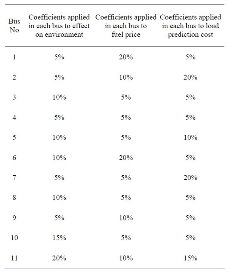
Table 11. An example of the weights of each parameter.
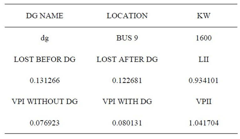
Table 12. The program outputs.
7. Conclusions
In this paper, we studied the effects of the significant parameters (such as reliability, loss reduction and efficiency) to optimally enhance the cost parameters (such as loss reduction, voltage profile improvement, environmental effects, fuel price and costs of predicting load of each bus). The cost parameters are variables which depend on the status and position of each bus of the power network. Unlike the previous works on intelligent DG placement which all consider just a few parameters to be optimized; the proposed method uses all possible significant parameters into account to be formulized and optimized.
A Genetic Algorithm based method has been developed in the DIGSILENT environment to apply to a sample IEEE 13-bus network to show the cost parameter optimization. It has been shown that any changes made in the weight of parameters such as loss reduction, voltage profile coefficient, coefficient of environmental pollution, fuel price and load prediction cost in the destination function of Genetic Algorithm directly affect the optimal DG capacity and placement.
The final DG placement will be carried out with the purpose of improving voltage profile and loss reduction which cause the distributed generation capacity to be floating. In addition, it is concluded that the selection of distributed generation technology for specific and optimal placement purposes should be based on the types of the DG technology, while it should be condition-based and purpose-based as well.
REFERENCES
- S. M. Moghadas-Tafreshi, “Electrical Energy Generation Resources in 21st Century,” Khaje Nasir Toosi University of Technology Press, Tehran, 2005.
- M. Fotuhi-Firuzabad and A. Rajabi-Ghahnavie, “An Analytical Method to Consider DG Impacts on Distribtion System Reliability,” IEEE/PES Transmission and Distribution Conference and Exhibition: Asia and Pacific, Dalian, 1 January 2005, pp. 1-6. doi:10.1109/TDC.2005.1547168
- W. El-Khattam and M. M. A. Salama, “Distributed Generation Technologies, Definitions and Benefits,” Electric Power System Research, Vol. 71, No. 2, 2004, pp. 119-128. doi:10.1016/j.epsr.2004.01.006
- R. E. Brown, P. Jiuping, F. Xiaornning and K. Koutlev, “Siting Distributed Generation to Defer T&D Expansion,” IEEE/PES Transmission and Distribution Conference and Exposition, Atlanta, 28 October-2 November 2001, pp. 622-627. doi:10.1109/TDC.2001.971309
- P. P. Barker and R. W. de Mello, “Determining the Impact of Distributed Generation on Power Systems. I. Radial Distribution Systems,” IEEE Power Engineering Society Summer Meeting, Seattle, 16-20 July 2000, pp. 1645-1656. doi:10.1109/PESS.2000.868775
- N. Hadisaid, J.-F. Canard and F. Dumas, “Dispersed Generation Impact on Distribution Networks,” IEEE Computer Applications in Power, Vol. 12, No. 2, 1999, pp. 22-28. doi:10.1109/67.755642
- M. A. Kashem and G. Ledwich, “Impact of Distributed Generation on Protection of Single Wire Earth Return Lines,” Electric Power System Research, Vol. 62, No. 1, 2002, pp. 67-80. doi:10.1016/S0378-7796(02)00031-7
- C. Dai and Y. Baghzouz, “On the Voltage Profile of Distribution Feeders with Distributed Generation,” IEEE Power Engineering Society General Meeting, Vol. 2, No. 2, 2003, pp. 1136-1140. doi:10.1109/PES.2003.1270484
- A. Girgis and S. Brahma, “Effect of Distributed Generation on Protective Device Coordination in Distribution System,” IEEE Conference on Large Engineering Systems, Halifax, 11-13 July 2001, pp. 115-119. doi:10.1109/LESCPE.2001.941636
- A. Robert and J. Marquet, “Assessing Voltage Quality with Relation to Harmonics, Flicker and Unbalance,” Proceedings of IEEE International Conference on Simulation, Modeling and Optimization, Lisbon, 16-18 November 2006, pp. 112-117.
- A. Von-Jouanne and B. Banergee, “Assessment Voltage Unbalance,” IEEE Transactions on Power Delivery, Vol. 16, No. 4 , 2001, pp. 782-790. doi:10.1109/61.956770
- J.-H. Teng, Y.-H. Liu, C.-Y. Chen and C.-F. Chen, “ValueBased Distributed Generator Placements for Service Quality Improvements,” International Journal of Electrical Power and Energy Systems, Vol. 29, No. 3, 2007, pp. 268-274. doi:10.1016/j.ijepes.2006.07.008
- R. K. Singh and S. K. Goswami, “Optimum Allocation of Distributed Generations Based on Nodal Pricing for Profit, Loss Reduction and Voltage Improvement Including Voltage Rice Issue,” International Journal of Electrical Power and Energy Systems, Vol. 32, No. 6, 2010, pp. 637-644. doi:10.1016/j.ijepes.2009.11.021
- Y. C. Huang H. T. Yang and C. L. Huang, “Solving the Capacitor Placement Problem in a Radial System Using Tabu Search Approach,” IEEE Transactions on Power systems, Vol. 11, No. 4, 1996, pp. 1868-1873. doi:10.1109/59.544656
- M. Kaplan, “Optimization of Number, Location, Size, Control Type and Control Setting of Shunt Capacitors on Radial Distribution Feeders,” IEEE Transactions on Power Apparatus and Systems, Vol. 103, No. 9, 1984, pp. 2659- 2665. doi:10.1109/TPAS.1984.318238
- Y. Baghzouz, “Voltage Regulation and Overcerrent Protection Issues in Distribution Feeders with Distribution Generation—A Case Study,” Proceeding of 38th Annual Hawaii International Conference on System Sciences, Hawaii, 3-6 January 2005, p. 66b. doi:10.1109/HICSS.2005.680
- H. D. Chiang and J. C. Wang, “Optimal Capacitor Placement Replacement and Control in Scale Unbalanced Systems,” IEEE Transactions on Power Apparatus and systems, Vol. 10, No. 1, 1995, pp. 363-369. doi:10.1109/59.373956
- T. E. Kim and J. E. Kim, “Voltage Regulation Coordination of Distributed Generation System in Distribution Systems,” IEEE Power Engineering Society Summer Meeting, Vancouver, 15-19 July 2001, pp. 480-484. doi:10.1109/PESS.2001.970073
- A. V. Jouanne and B. Banergee, “Assessment Voltage Unbalance,” IEEE Transactions on Power Delivery, Vol. 16, No. 4, 2001, pp. 782-790. doi:10.1109/61.956770