Communications and Network
Vol.5 No.1(2013), Article ID:28239,12 pages DOI:10.4236/cn.2013.51006
A Novel Optical Control Plane for Switching an Electro-Optical Hybrid Node in Translucent WDM Optical Networks
1Department of ECE, NIIT University, Rajasthan, India
2Division of ECE, Netaji Subhas Institute of Technology, New Delhi, India
Email: sridhar@nmsu.edu, Sridhar.Iyer@niituniversity.in, sps_nsit@yahoo.co.uk
Received December 11, 2012; revised January 12, 2013; accepted February 13, 2013
Keywords: Optical Control Plane; Translucent WDM Optical Network; Physical Layer Impairments; Regenerators; All-Optical Wave-Length Converters; GMPLS; PLI-SQARWA
ABSTRACT
In a translucent network scenario, development of an optical control plane (OCP) that is aware of the location and number of available regenerators and all-optical wavelength converters (AOWCs) is of paramount importance. However, current generalized multiprotocol label switching (GMPLS) protocol suite does not consider the distribution of regenerator and AOWC availability information to all the network nodes. In this paper, we propose a novel optical control plane (OCP) architecture that 1) disseminates information about network components (i.e. regenerators and AOWCs) to all the network nodes; and 2) evaluates candidate routes which use fewest amounts of network components. Performance of the proposed OCP is compared with a recently proposed hybrid OCP approach in terms of blocking performance, number of deployed components and lightpath establishment setup times. The obtained simulation results show that the proposed OCP approach demonstrates low connection blocking and establishes lightpaths by 1) minimizing the overall network cost owing to the deployment of minimum total number of network components; and 2) demonstrating acceptable lightpath establishment setup times at all traffic loads. Further, the proposed OCP methodology is compatible and suitable for controlling the operations of a novel electro-optical hybrid translucent node which is a latency efficient technology capable of delivering a cost effective implementation suitable for large scale deployment.
1. Introduction
In opaque wavelength division multiplexed (WDM) optical networks, signals undergo optical-electrical-optical (OEO) conversions at each intermediate node thus purveying a-priori admissible quality of transmission (QoT) at the expense of costly 3R (re-amplify, reshape and re-time) electrical regenerators which contribute to both, capital and operational expenditures (CapEx and OpEx). With the new generation of commercially available optical network elements, the paradigm shift towards transparent (all-optical networks) WDM optical networks has evolved wherein; signals are transmitted in the optical domain from source to the destination. The flexibility and high capacity provided by transparent networks though are faced with physical layer impairment (PLIs) inherent in the fiber and further, these networks suffer from inefficient wavelength utilization as a connection request may be rejected due to unavailability of a common wavelength on all the links along the chosen route [1]. For the above reasons, in order to provision demands due to signal quality or wavelength contention requirements, the usual solution is to regenerate the signal(s) at intermediate nodes. The imminent transparency disruption of signals due to OEO conversions and increase in the overall network cost by the introduction of regenerators has led to the emergence of translucent WDM networks which exploit sparse placement (i.e., installed in a limited number of nodes) of regenerators, thus representing a promising trade-off between transparent and opaque networks [2]. Hence, translucent networks are able overcome the reach limitations due to QoT degradation by PLIs, simultaneously keeping network cost limited [3].
In translucent WDM networks, for each lightpath request, a route must be found, specifying both, link resources (i.e., wavelength channels) and node resources (i.e., OEO regenerators and all-optical wavelength converters-AOWCs) to be used. In addition, a node must also be provided with the information pertaining to 1) link and node QoT parameters and wavelength conversion (WC) requirements; and 2) availability of installed regenerators and AOWCs at the nodes. Owing to the former information, a node is aware of the QoT degradation and WC requirements along every eligible path whereas, owing to the latter information, in the case of critical QoT and/or wavelength collisions, a node can choose the regenerators and/or AOWCs to be exploited. Existing studies on translucent network design focus on 1) physical layer impairment-routing and wavelength assignment (PLI-RWA) approaches for incorporating PLIs during lightpath computation; 2) selecting regeneration sites and number of regenerators to be deployed on these sites (regenerator placement (RP) problem) and/or; 3) given sparse placement of regenerators, selecting which of these regenerators to use (regenerator allocation (RA) problem) [4]. These existing studies present the following two major drawbacks:
1) They are based on shortest path (SP) routing protocols since; SP routing sufficiently achieves the desired performance. However, the SP approach contributes significantly to network congestion and also comes short of provisioning efficient network utilization, since traffic characteristics and resource availability are not a part of its routing decisions. Further, owing to the existence of non-uniform PLIs and heterogeneity of real optical networks, SP may not always demonstrate the best signal quality. Hence, it may occur that any other route(s), apart from the SP, exhibits better signal quality, thus requiring fewer intermediate regenerators, in turn, lowering the overall network cost.
2) They assume that regenerators are also equipped with WC capability. In cases when signal(s) require only WC, such an assumption may not be viable as OEO conversion leads to time delay. Thus, for only wavelength contention resolution, it is viable to use an AOWC in order to reduce the delay introduced by OEO conversions. For cases when only regeneration or simultaneous regeneration and WC are required, a regenerator can be used.
In order to tackle the above mentioned drawbacks of existing translucent network design studies, in our previous work, we have proposed:
1) An innovative PLI-Signal Quality Aware RWA (PLI-SQARWA) algorithm [5] that 1) guarantees zero blocking due to signal degradation and wavelength contention, and 2) minimizes the total required network components by a) considering signal quality to route connections over paths requiring fewest numbers of regenerators, and b) maximally using placed regenerators for WC before resorting to AOWCs, and 2) An electro-optical hybrid translucent node architecture [6] that uses regenerators if a) the Quality-factor (Q-factor) at any node falls below the threshold or b) the Q-factor at any node falls below the threshold and simultaneously there is also wavelength contention. In the latter case, the hybrid node uses a regenerator for both, regeneration and WC. However, if only wavelength contention is to be resolved, the hybrid node resorts to an AOWC instead of a regenerator.
In a translucent WDM network scenario, the implementation of an efficient optical control plane (OCP) that provisions distributed signaling and routing mechanisms throughout the network is of paramount importance. The GMPLS based OCP, which is the de facto standard and implementation of the OCP used for disseminating information in translucent WDM networks, is based on two main distributed protocols: 1) the Open Shortest Path First with Traffic Engineering Extensions (OSPF-TE) routing protocol that floods the network topology and TE information used for path computation; and 2) the Resource Reservation Protocol with Traffic Engineering Extensions (RSVP-TE) signaling protocol that is responsible for the actual lightpath establishment. Figure 1 shows the existing optical network layers wherein; the OCP is responsible for TE, route computation and signaling; while the data plane is responsible for switching the data belonging to different connections based on OCP instructions.
However, standard GMPLS does not account for the QoT, regenerator and AOWC information and hence, no solutions have been standardized yet for the issue of encompassing QoT, regenerator or AOWC information within the GMPLS-controlled translucent networks [7]. The presence of regenerators and AOWCs necessitates the OCP to decide on which regenerators and/or AOWCs to be used while setting up 1) a translucent lightpath or 2) an end-to-end lightpath composed of multiple transparent sections. In order to solve QoT distribution issues, studies in [8-10] have proposed the inclusion of QoT parameters within both, the RSVP-TE and OSPF-TE protocols. Recently, studies focussing on GMPLS extensions in the context of regenerator information dissemination have been proposed [11-13].
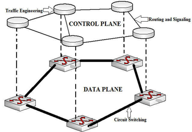
Figure 1. Optical network layers: control plane and data plane.
In [11,12], extensions to both, RSVP-TE and OSPFTE protocols are proposed in order to account for shared regenerators in translucent networks. In [11], the authors have proposed lightweight GMPLS extensions to account for shared regenerators in translucent networks during lightpath establishment. Firstly, a signaling approach based on dynamic estimation of optical signal quality during the lightpath setup process is applied, which is then extended to encompass the presence of shared regenerators. An intermediate node designates itself for regeneration during the signaling phase if, QoT of a transparent section, terminating at the node, falls below the pre-defined threshold value. Results of the study show that networks demonstrating few critical situations can be setup without 1) significantly affecting the lightpath blocking probability; and 2) compromising on the routing protocol scalability.
The authors in [12] have proposed GMPLS extensions to encompass the presence of shared regenerators without routing protocol modifications. The regenerator object (RO) is introduced within the RSVP-TE to identify the nodes designated for regeneration. In addition, other extensions to RSVP-TE (i.e., the regenerator availability object—RAO) and to OSPF-TE (i.e., the regenerator information node state advertisement—RI-NSA) are proposed to distribute regenerator availability information. In order to setup a lightpath, the gathered regenerator information is utilized only by the source node and the results show that low blocking is obtained without requiring any routing protocol modification.
The authors in [13] have concentrated on the study of OCP and management approaches for translucent WDM networks. A hybrid OCP is proposed, which combines the best features of both, routing based information updating and signaling-based data collection approaches thus, necessitating extensions to both, routing and signaling protocols. When the connection request arrives at the source node, first a k hybrid weight shortest path first (k-HW-SPF) route computation algorithm is implemented to provide up to k possible routes according to the information in Simplified Global-Resource Related Database (SG-RRD) and Simplified Global-Physical Impairments Database (SG-PID). The calculated routes are then passed to RSVP-TE extension module, and parallel transmitted by k Path (i.e. message denoting the request for a connection) messages. In the forward direction, every traverse node, before propagating the Path message, updates the collected data by adding its own dynamic parameters and resources state to the corresponding objects of RSVP message. At the same time, the RA strategy is implemented for signal quality estimation and RA. At the destination, node picks the first incoming Path message and queues the other arriving messages. The results comparing hybrid OCP with signaling-based OCP and routing-based OCP show that hybrid OCP exhibits the lowest blocking probability, but at the cost of longer setup delays and increased number of regenerators for each path. The authors conclude that hybrid OCP is able to conquer the limitations of existing approaches under various traffic conditions, and is hence a suitable solution for connection management in translucent WDM networks.
However, the aforementioned studies do not consider distribution of AOWC information to the network nodes. These studies assume that the transparent lightpath sections comprising the translucent lightpath are subject to wavelength-continuity constraint. In this paper, we contrive an architecture that underpins the OCP design problem in translucent networks. The contributions of this paper are twofold:
• A novel OCP architecture is proposed which: 1) ensures that a node designated for regeneration and/or WC reserves regenerator and/or AOWC for a given lightpath, and further, also performs regeneration and/or WC, and 2) unlike previous studies [11,12]; in which regenerator information is utilized only by the source node to setup a lightpath; distributes the regenerator and/or AOWC capability and availability information to all the nodes by utilizing the regenerator database (RD) and AOWC database (AOWCD). The RD and AOWCD are installed in each node and store the number of installed and/or available regenerators and AOWCs at each node. Thus, the proposed OCP approach is compatible and suitable for controlling the switching operations of the hybrid node.
• Deviating from existing studies that use SP routing protocols, the PLI-SQARWA algorithm is employed for RWA. PLI-SQARWA minimizes connection blocking and also results in minimum number of network components being deployed, thus also minimizing the overall network cost.
It must be noted that, storing the regenerator and AOWC information at only the source node and further, this information being used only by the source node to setup the lightpaths, leads to high congestion and blocking. However, regenerators and AOWCs information, when disseminated to all the network nodes, can considerably reduce the congestion and blocking. This can be explained as follows: for only the source node establishing the lightpaths by utilizing the regenerator and AOWC information, in the case of a node failure along the path, the Path message(s) will be required to traverse back all the way to the source node in order to retrieve the information hence, increasing the lightpath setup attempts and setup time. In case of many such failures, network congestion will result leading to connection blocking. On the other hand, in the case of regenerator and AOWC information being disseminated to all the network nodes, in the event of a node failure along the path, regenerator and AOWC information can be retrieved from the neighbouring nodes, hence reducing the lightpath setup attempts and setup time. This in turn will also reduce the network congestion and connection blocking. In addition, storing the information at only the source node leads to setup of only a few parallel lightpaths whereas, by distributing it to all network nodes, the information can be exploited for many parallel lightpath setups and also for setup of subsequent lightpath requests [12].
The remainder of the paper is organized as follows. Section 2 describes the translucent network model considered in the study. In Section 3, we describe details of the proposed OCP approach. Section 4 presents the numerical results wherein; we discuss the simulation assumptions, the performance metrics used in the study, the analysis to evaluate setup times for the lightpaths, and the simulation results. Finally, section 5 presents the conclusion of this study.
2. Network Model
The considered translucent network comprises of N nodes and L bi-directional links, with each link supporting W wavelengths per direction. For the fulfillment of regeneration and/or WC requirement, we resort to the deployment of the hybrid node as shown in Figure 2. The wavelength converter within the hybrid node is based on four wave mixing (FWM) in semiconductor optical amplifier (SOA) and is assumed to be ideal or full range wavelength converter (FRWC), i.e. it can convert any input wavelength to any output wavelength [5,6].
A lightpath transiting such a node may be switched transparently (L1) or directed to the regenerator pool (L2) if 1) it requires only regeneration or; 2) it simultaneously requires both regeneration and WC. If only wavelength contention is to be resolved, the lightpath is directed to the wavelength converter (L3). Fiber links are deployed using standard non-zero dispersion shifted fibers and erbium-doped fiber amplifiers (EDFAs) are deployed every fiber span (typically every 80Km) in order to recover from fiber losses. The placement of hybrid nodes (i.e., required regenerators and AOWCs) in the network is chosen by the PLI-SQARWA algorithm. Figure 3 shows the architecture of the proposed OCP for translucent WDM network wherein; the switching fabric comprises of the electro-optical hybrid nodes.
As proposed in [14], it is assumed that at each node, the OCP stores wavelength availability information in the traffic engineering database (TED), which is updated through the signal quality aware routing (SQAR-TE) flooding [5]. Moreover, each node maintains an updated knowledge of the optical layer by storing the QoT parameters and WC requirements in the QoT parameter database (QPD) and WC requirement database (WCD) respectively. Therefore, each node is able to determine the feasibility of a path in terms of QoT and wavelength continuity constraint. Further, following the study in [12], the regenerator object (RO) and the AOWC object (AOWCO), which contain an entry of each node designated for regeneration and WC respectively, are also included within the signaling messages.
3. Optical Control Plane Design
3.1. Problem Definition
In this sub-section we describe the OCP design problem statement which can be stated as follows:
Given
1) A network topology;
2) A set of available wavelengths per fiber link;
3) The offered traffic with a set of static demands;
4) An admissible Q-factor threshold value i.e. Qth.
Objective
To evaluate, either a feasible transparent path (if it exists) or a translucent path (comprised of multiple transparent sections), with minimum number of network
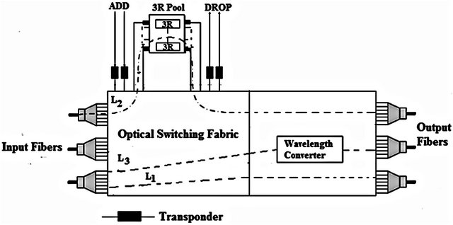
Figure 2. Electro-optical hybrid translucent node architecture.
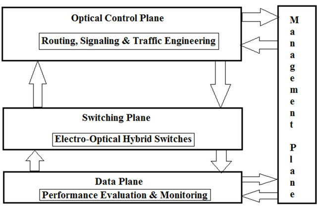
Figure 3. Architecture of the proposed OCP.
components (i.e. regenerators and AOWCs) deployed along all the links, in effect, minimizing the overall network cost, and simultaneously ensuring minimum connection blocking and setup time for the lightpath establishment.
Subject to
Signal quality constraint: For any network lightpath, at its destination node, the corresponding Q-factor value must not fall below the pre-defined threshold value.
Minimum cost constraint: For any network lightpath, regeneration and/or WC requirements must be satisfied ensuring the deployment of minimum number of components along all the links.
Setup Delay Constraint: For any network lightpath, delay between its arrival and establishment must be minimized and must not exceed a pre-defined setup time value. In the current study, the setup time incurred must not exceed a given setup timeout , which is assumed to be user adjustable.
3.2. Proposed Optical Control Plane Approach
In this sub-section, we present details of the proposed OCP approach which comprises of two phases. The flow chart of the proposed OCP is described by the diagram on Figure 4.
Phase I. Routing and Component Deployment Phase
In this phase, the proposed OCP uses the PLI-SQARWA algorithm in order to 1) select a candidate route based on signal quality and 2) deploy minimum numbers of network components along the selected lightpath. This phase comprises of the following six steps:
Step 1. For a lightpath request from source node to the destination node, compute a candidate path using the SQAR algorithm, that selects the route based on signal quality, and go to step 2.
Step 2. Check the QoT and WC requirements of the candidate lightpath by probing the QPD and WCD respectively stored at every node, and go to step 3.
Step 3. If a transparent lightpath is available, go to phase 2, else go to step 4.
Step 4. If no transparent lightpath is available due to wavelength collision and/or unacceptable QoT, run 1) the wavelength assignment (WA) & wavelength converter placement (WCP) algorithm phase, and 2) RP algorithm phase, of the PLI-SQARWA algorithm, which ensures the minimization of the overall network cost. Go to step 5.
Step 5. Designate the hybrid nodes for regeneration and/or WC based on regenerator and AOWC information stored in the RD and AOWCD respectively of every node. Go to step 6.
Step 6. Establish the translucent lightpath by switching the deployed hybrid nodes, as per the requirement of 1) regeneration, 2) simultaneous regeneration and WC, or 3) only WC. In other words, by appropriately switching and using the designated hybrid nodes, partition the selected candidate lightpath into appropriate number of transparent sections with acceptable QoT and/or wavelength continuity along the links, and go to phase 2.
Phase II. Signaling Phase
In this phase, both, the transparent and translucent lightpaths resort to a signaling session for reserving the required components in order to establish the lightpaths. The signaling session comprises of the following ten steps:
Step 1. At an intermediate node i, upon receipt of the signaling Path message, check if node i is listed in the RO and/or the AOWCO. If node i is not listed in the RO and/or the AOWCO, go to step2. Else, if node i is listed in the RO and/or the AOWCO, go to step 3.
Step 2. Forward the signaling Path message to the next node along the path and designate the next node as node i. If this next node (i.e. node i) is an intermediate node, then go to step 1. Else, if this next node (i.e. node i) is the destination node, then go to step 6.
Step 3. Probe the QPD and/or WCD to check the QoT and/or WC requirement of the transparent section terminating at node i, and go to step 4.
Step 4. If the transparent section terminating at node i has an acceptable QoT and/or satisfies the wavelength continuity constraint, from node i, forward the Path message without modifying the RO and/or AOWCO, and go to step 6. Else, go to step 5.
Step 5. If the transparent section terminating at node i does not have an acceptable QoT and/or does not satisfy the wavelength continuity constraint, reserve the regenerator and/or AOWC as per the requirement, and further, modify the RO and/or AOWCO accordingly. In other words, switch the hybrid node as per the requirement of 1) regeneration; 2) simultaneous regeneration and WC, or 3) only WC, and upgrade both, the RO and/or AOWCO as
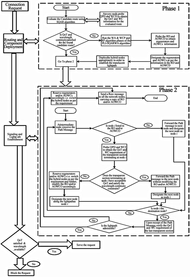
Figure 4. Synopsis of the proposed OCP.
required. Go to step 6.
Step 6. Designate the next node along the lightpath as node i. If this next node (i.e. node i) is an intermediate node, go to step 1. Else, if this next node (i.e. node i) is the destination node, go to step 7.
Step 7. At the destination node, upon receipt of the Path message, verify the QoT and/or wavelength continuity of the last transparent section, and go to step 8.
Step 8. If the lightpath is not admissible, reserve the regenerator and/or AOWC as per the requirement i.e., switch the hybrid node as per the requirement of 1) regeneration; 2) simultaneous regeneration and WC; or 3) only WC, and go to step 10. Else go to step 9.
Step 9. If the lightpath is admissible, send a Resv message (i.e. message denoting the reservation of required number of components for lightpath establishment) carrying a copy of the received RO and/or AOWCO, from the destination node, towards all the network nodes along the lightpath, and go to step 10. It must be noted that the Resv message stored at all the nodes along the lightpath, aids in future lightpath establishments, since the network is aware of the reserved components.
Step 10. Terminate the algorithm.
4. Numerical Results
In this section, we first precise our simulation environment and characteristics, then present the performance metrics used in the study and finally, discuss the obtained numerical results.
4.1. Simulation Assumptions
We conducted extensive simulations on a dual core 2.20 GHz computer with 1 GB RAM using the MatLab and C++ software in order to investigate the N = 18 node NSFNET network depicted in Figure 5. The network consists of L = 29 bi-directional links with W = 16 wavelengths per fiber link. In the current study, Q-factor threshold takes the value of 6 which corresponds to a bit error rate (BER) of 10−9. The optical physical layer is modeled as in our previous work, which considers an Intensity Modulation/Direct Detection (IM/DD) system based on on-off Keying (OOK) and non-return-to-zero (NRZ) modulation [15]. In view of longer optical reach of the signals with the aim of utilizing minimum amount of OEO regenerators, we have considered channels operating at a bit-rate of 10 Gb/s. Further, lightpath QoT evaluation is based on the realistic estimation of signal quality considering the simultaneous impact of three effects viz. stimulated Raman scattering (SRS), FWM, and amplified spontaneous emission (ASE) noise.
We consider permanent lightpath demands (PLDs) which are offline requests that consist of pre-known connection demands with data rate equal to full capacity of the wavelength channel and are thus established through a full lightpath. In particular, both, the inter-arrival and the holding times are exponentially distributed with a mean time of  (with
(with  ms) and
  (with
(with  ms) respectively. Let
  and
and  denote the mean time and the average service time, respectively. Hence, the duration of each request is exponentially distributed with an average time that fluctuates between the 1) sum of mean time and average service i.e.
 , and 2) mean time
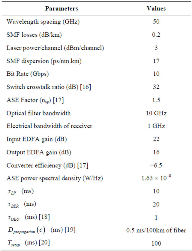
 . It must be noted that the type of requisite service decides the service time for a demand, which is related to the processing delay, that in turn depends on if the connection requires 1) only regeneration; or 2) simultaneous regeneration and WC; or 3) only WC. In the current study, for WC, since no OEO conversions are required, the processing delay is assumed to be zero whereas, regeneration, which necessitates OEO conversion, is considered to incur a considerable (fixed) amount of processing delay. Table 1 summarizes the various transmission system parameters adopted in our simulations.
4.2. Performance Metrics
In the current study, the following metrics have been used for the performance evaluation:
1) Blocking Probability (BP): The ratio between numbers of blocked (rejected) lightpaths and the total number
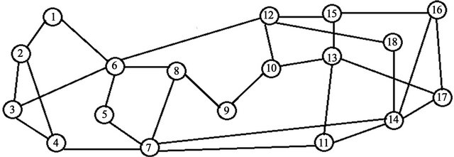
Figure 5. 18 node NSFNET network.
Table 1. Transmission system parameters.
of lightpath requests.
2) Total Number of components: The number of components (i.e., regenerators + AOWCs) deployed within the network to establish the lightpath connections.
3) Average setup time: The average time between the lightpath request arrival and lightpath establishment, among all the accepted lightpath requests.
4.3. Setup Time Analysis
For the evaluation of the lightpath setup time, we use the following analysis: A connection demand i.e., a lightpath “c” is assumed to incur a total set up time, denoted as . The lightpath is blocked if the set up incurs a time that exceeds a given timeout, which is assumed to be user adjustable with delay bound denoted as
 . Further, as per the requirement(s) of regeneration and/or WC, the reservation of the components (i.e. regenerators and AOWCs), along the lightpath incurs a signaling time, denoted as
 .
.
For a lightpath, if within the timeout threshold and without requiring OEO conversion (i.e. no electrical regenerators), processing time,  is given as
 (1)
(1)
where  is the time required to find a candidate lightpath,
 ![]() the time to run BER estimation and
the time to run BER estimation and ![]() denotes the number of trials before which a “good” (BER less than threshold) lightpath is calculated or below which the check for all candidate lightpaths is finished.
denotes the number of trials before which a “good” (BER less than threshold) lightpath is calculated or below which the check for all candidate lightpaths is finished.
On the other hand, for a lightpath, if within the timeout threshold and requiring OEO conversion (i.e. electrical regenerators), the processing time is given as
 (2)
(2)
where  denotes the delay in OEO conversion. Let the propagation time be denoted by
 , which is the time involved in carrying the lightpath along the link between two nodes of the network. Thus, the total set up time for a lightpath “c” is given as
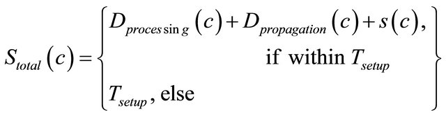 (3)
(3)
Other delays apart from processing and propagation delays have been ignored in the analysis and since, AOWC does not involve electrical regeneration, it is assumed that WC does not introduce any delay.
4.4. Simulation Results
This sub-section analyses performance of the proposed OCP, which is named as P-OCP, by means of comparison with the recently proposed hybrid-OCP approach, which is named as H-OCP [13]. The H-OCP approach has been executed for range of different values of a set of specific parameters that adjust in order to determine how the solution space is explored heuristically. The results shown in this paper correspond to those parameters which provided the best performances and their values are reproduced so as to allow the results to be repeatable: 1) for the computation of k-HW-SPF routes associated to each demand, the value of k is set to 5; 2) the trace-forward strategy is used for signaling based RA; 3) the lightpath quality estimation (LQE) module is used to model the PLI effects, 4) the OCP topology is assumed to be same as that of the data plane, and 5) random selection strategy is used for WA. The simulations cover 6 traffic loads that range from 100 to 500 connection demands and for each load, 10 static traffic matrices are generated stochastically according to uniform distribution. Thus, presented results are average values of ten simulation runs.
In Figure 6, variation of BP with traffic load has been plotted for both the OCP approaches. It can be observed from the figure that 1) For low traffic loads, both, H-OCP and P-OCP show zero BP. This can be attributed to the fact that for
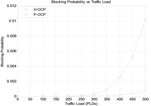
Figure 6. H-OCP versus P-OCP: blocking probability versus traffic load.
both the algorithms:
a) Regeneration and WC is provisioned which eradicates blocking due to signal degradation and wavelength contention respectively, and b) Owing to low loads, the network is not overloaded and ample resources are available.
2) For intermediate and high traffic loads, blocking starts to occur for both the algorithms owing to unavailability of resources. It can be observed that H-OCP shows higher blocking compared to the proposed P-OCP approach. This can be attributed to the fact that:
a) For H-OCP, as load increases, owing to the use of K-HW-SPF routing, which is founded on SP routing protocol, higher network overloading occurs, resulting in unavailability of resourcesb) For P-OCP, rather than the SPs, majority of the “Best Paths” are selected as the candidate routes which leads to larger resources being available even at higher traffic loads. The low blocking observed at higher loads in the case of P-OCP is due to the fact that PLISQARWA selects few SP routes as candidate routes.
It can also be deduced from Figure 6 that for low loads, both OCP approaches accept all the demands whereas, between moderate and high loads, both the approaches are able to maintain acceptable blocking.
In Figure 7, the average total numbers of required components, with respect to traffic load, has been plotted for both the OCP approaches.
It must be noted that in the H-OCP approach, regenerators are used for both, regeneration and WC whereas, in the P-OCP approach, regenerators are used for 1) only regeneration or 2) simultaneous regeneration and WC whereas, for only WC, AOWCs are used. It can be observed from the figure that:
1) For low traffic loads, both approaches require approximately the same number of components.
2) For moderate to high values of traffic load, H-OCP requires larger number of components compared to the proposed P-OCP approach. This occurs due to the fact that for k-H-OCP (k > 1), large number of regenerators are required for each path in order to overcome both, wavelength contention and signal degradation. Thus, acceptable blocking performance shown by H-OCP between moderate and high loads (as shown in Figure 6) is at the expense of increased number of required components. The increase in the number of total components is by a factor of:
a) 1.96 when the load is 400 andb) 2.17 when the load is 500.
Figure 8 shows the average setup time of the two OCP schemes with respect to the traffic load. It can be observed from the figure that At low traffic loads (between 50 and 150 demands); owing to the use of destination-initiated resource reservation, the setup delay for H-OCP is more than that of P-OCP which is based on source-initiated resource reservation. Further, the use of regenerators for both, regeneration and WC results in larger delay in the case of H-OCP compared to P-OCP which uses regenerators for 1) only regeneration or 2) simultaneous regeneration and WC; and AOWCs for only wavelength contention resolutions.
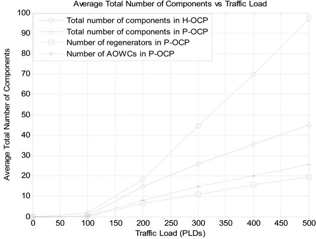
Figure 7. H-OCP versus P-OCP: number of components versus traffic load.
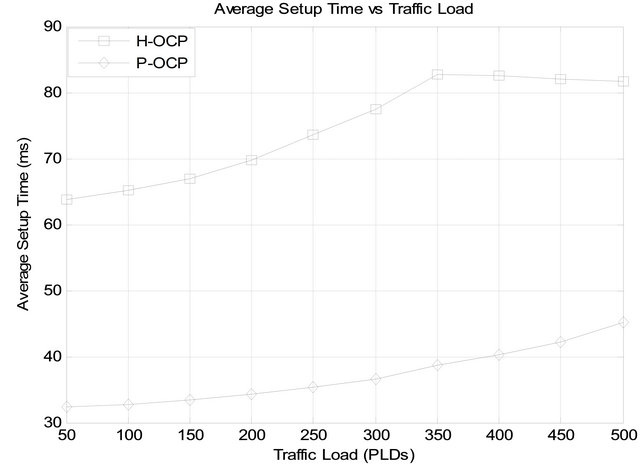
Figure 8. H-OCP versus P-OCP: average setup time versus traffic load.
At moderate traffic loads (between 200 and 300 demands), the setup delay for H-OCP increases due to excessive time required for multiple lightpath setup-attempts; since k-H-OCP has at most k path setup-attempts according to the path probe information at the destination [13]. On the contrary, for P-OCP, the setup times increase slightly with increase in the load. This is due to the fact that, for the P-OCP approach, information required for lightpath establishment (i.e., number of installed and/or available regenerators and/or AOWCs) is stored at every network node, which results in lesser lightpath setup attempts resulting in lower lightpath setup times.
At high traffic loads (beyond 350 demands); the setup delay for H-OCP starts to decrease slightly. This occurs since for longer lightpaths, the BP is high, which reduces the average setup delay. On the other hand, for P-OCP, the average setup time increases with network load because an increasing number of lightpaths are established (i.e. BP is very low) by discovering the available components within the network.
Hence, it can be inferred from Figure 8 that, there exists a definitive trade-off between BP and lightpath setup time. Overall, compared to H-OCP, P-OCP is able to maintain lower BP and lightpath setup times for all traffic load values.
5. Conclusions
In this paper, we proposed a novel OCP architecture that 1) disseminates information about both, regenerators and AOWCs to all the network nodes; 2) reduces the overall network cost and connection blocking; and 3) demonstrates acceptable lightpath setup times at all traffic loads. In view of a translucent WDM network, performance of the proposed OCP (P-OCP) is compared with a recently proposed hybrid OCP (H-OCP) approach.
Simulation results show that compared to H-OCP, owing to the use of PLI-SQARWA for RWA, P-OCP is able to 1) maintain acceptable blocking at moderate and high traffic loads, and 2) ensure the deployment of least amount of components within the network. In terms of the lightpath setup times, P-OCP outperforms H-OCP at all traffic loads. However, at high traffic loads, the setup time for H-OCP starts to decrease slightly owing to high BP, as longer lightpaths are more likely to be blocked; whereas, for P-OCP, the setup time increases with the traffic load owing to increased number of lightpaths being established. Hence, it can be concluded that there exists a trade-off between obtaining a specific blocking performance and lightpath establishment setup time. Overall, compared to H-OCP, P-OCP is able to maintain lower setup times and BP at all traffic loads. Finally, the proposed OCP is compatible and suitable for controlling the operations of the electro-optical hybrid translucent node.
6. Acknowledgements
The authors would like to thank the AICTE for funding this work under research promotion scheme (RPS-11/ 2008-09).
REFERENCES
- C. V. Saradhi, S. Zaks, R. Fedrizzi, A. Zanardi and E. Salvadori, “Practical and Deployment Issues to Be Considered in Regenerator Placement and Operation of Translucent Optical Networks,” Proceedings of IEEE International Conference on Transparent Optical Networks (ICTON), Munich, 27 June-1 July 2012, pp. 1-4. doi:10.1109/ICTON.2010.5549297
- J. Berthold, A. Saleh, L. Blair and J. Simmons, “Optical networking: Past, Present, and Future,” IEEE Journal of Lightwave Technology, Vol. 26, No. 9, 2008, pp. 1104- 1118. doi:10.1109/JLT.2008.923609
- G. Shen and R. S. Tucker, “Translucent Optical Networks: The Way Forward,” IEEE Communications Magazine, Vol. 45, No. 2, 2007, pp. 48-54. doi:10.1109/MCOM.2007.313394
- S. P. Singh, S. Iyer, S. Kar and V. K. Jain, “Study on Mitigation of Transmission Impairments and Issues and Challenges with PLIA-RWA in Optical WDM Networks,” Journal of Optical Communications, De-Gruyter, Vol. 33, No. 2, 2012, pp. 83-101. doi:10.1515/joc-2012-0015
- S. Iyer and S. P. Singh, “A Novel Offline PLI-RWA and Hybrid Node Architecture for Zero Blocking and Time Delay Reduction in Translucent Optical WDM Networks,” Communications and Networks, Scientific Research, Vol. 4, No. 4, 2012, pp. 306-321. doi:10.4236/cn.2012.44036
- S. Iyer and S. P. Singh, “A Novel Hybrid Node Architecture for Reducing Time Delay in Wavelength Division Multiplexed Translucent Network,” Proceedings of IEEE National Conference on Communication (NCC), Kharagpur, 3-5 February 2012, pp. 1-5. doi:10.1109/NCC.2012.6176843
- N. Sambo, N. Andriolli, A. Giorgetti, I. Cerutti, L. Valcarenghi, P. Castoldi and F. Cugini, “GMPLS-Controlled Dynamic Translucent Optical Networks,” IEEE Network, Vol. 23, No. 3, 2009, pp. 34-40. doi:10.1109/MNET.2009.4939261
- R. Martinez, C. Pinart, F. Cugini, N. Andriolli, L. Valcarenghi, P. Castoldi, L. Wosinska, J. Comellas and G. Junyent, “Challenges and Requirements for Introducing Impairment-Awareness into the Management and Control Planes of ASON/GMPLS WDM Networks,” IEEE Communications Magazine, Vol. 44, No. 12, 2006, pp. 76-85. doi:10.1109/MCOM.2006.273103
- E. Salvadori, Y. Ye, C. V. Saradhi, A. Zanardi, H. Woesner, M. Carcagnì, G. Galimberti, G. Martinelli, A. Tanzi and D. La Fauci, “Distributed Optical Control Plane Architectures for Handling Transmission Impairments in Transparent Optical Networks,” IEEE Journal of Lightwave Technology, Vol. 27, No. 13, 2009, pp. 2224-2239. doi:10.1109/JLT.2008.2006066
- F. Cugini, N. Sambo, N. Andriolli, A. Giorgetti, L. Valcarenghi, P. Castoldi, E. Le Rouzic and J. Poirrier, “Enhancing GMPLS Signalling Protocol for Encompassing Quality of Transmission (QoT) in All-Optical Networks,” IEEE Journal of Lightwave Technology, Vol. 26, No. 19, 2008, pp. 3318-3328. doi:10.1109/JLT.2008.925674
- N. Sambo, F. Cugini, N. Andriolli, A. Giorgetti, L. Valcarenghi and P. Castoldi, “Lightweight RSVP-TE Extensions to Account for shared Regenerators in Translucent Optical Networks,” Proceedings of IEEE Photonics in Switching (PIS), San Francisco, 2007, pp. 35-36. doi:10.1109/PS.2007.4300731
- F. Cugini, N. Sambo, N. Andriolli, A. Giorgetti, L. Valcarenghi, P. Castoldi, E. L. Rouzic and J. Poirrier, “GMPLS Extensions to Encompass Shared Regenerators in Transparent Optical Networks,” Proceedings of IEEE European Conference and Exhibition of Optical Communication (ECOC), Berlin, 16-20 September 2007, pp. 1-2.
- L. Wang, J. Zhang, Y. Zhao and W. Gu, “Study of Optical Control Plane for Translucent WDM Networks,” Photonic Network Communications, Vol. 20, No. 1, 2012, pp. 64-74. doi:10.1007/s11107-010-0246-2
- D. Li, Y. Lee, and J. Gao, “Evaluation of IGP Extensions for Wavelength Switching Optical Networks,” IETF Internet Draft, 2007, pp. 1-16. http://tools.ietf.org/pdf/draft-li-ccamp-wson-igp-eval-01.pdf
- S. Iyer and S. P. Singh, “Impact of Combined Nonlinearities and ASE Noise on Performance of 10 Gbps All Optical Star WDM Networks,” Scientific Research, Communications and Network, Vol. 3, No. 4, 2011, pp. 235-249. doi:10.4236/cn.2011.34028
- B. Ramamurthy, D. Datta, H. Feng, J. P. Heritage and B. Mukherjee, “Impact of Transmission Impairments on the Teletraffic Performance of Wavelength-Routed Optical Networks,” IEEE Journal of Lightwave Technology, Vol. 17, No. 10, 1999, pp. 1713-1723. doi:10.1109/50.793740
- S. P. Singh, S. Kar and V. K. Jain, “Performance of AllOptical WDM Network in Presence of Four-Wave Mixing, Optical Amplifier Noise, and Wavelength Converter Noise,” Fiber & Integrated Optics, Vol. 26, No. 2, 2007, pp. 79-97. doi:10.1080/01468030601131477
- K. J. Kwak and E. G. Coffman, “Retransmission in OBS Networks with Fiber Delay Lines,” Proceedings of IEEE International Conference on Broadband Communications, Networks and Systems (BROADNETS), Raleigh, 10-14 September 2007, pp. 243-249. doi:10.1109/BROADNETS.2007.4550431
- MRV Communications, “The Low Latency Network Design Considerations,” White Paper, MRV-AN-Low Latency, Optical Communication Systems, 2010. http://www.mrv.com/library/docs/PDF72/MRV-WP Low-Latency.pdf
- J. He, M. Brandt-Pearce and S. Subramaniam, “QoSAware Wavelength Assignment with BER and Latency Guarantees for Crosstalk Limited Networks,” Proceedings of IEEE International Conference on Communications (ICC), Glasgow, 24-28 June 2007, pp. 2336-2341. doi:10.1109/ICC.2007.392