Communications and Network
Vol.3 No.4(2011), Article ID:8473,6 pages DOI:10.4236/cn.2011.34027
Turbo Codes—A New PCCC Design
Physics Department, University of Ioannina, Ioannina, Greece
E-mail: schrono@cc.uoi.gr, gtatsis@grads.uoi.gr, kostarakis@uoi.gr
Received October 3, 2011; revised November 1, 2011; accepted November 10, 2011
Keywords: Turbo Codes, Convolutional Codes, SOVA, SISO, SCCC, PCCC, Random Interleavers, Iterative Decoding, APP Decoder, Puncturing, AWGN, Noise Variance
Abstract
Coding techniques have always been a major area of scientific interest. Due to this interest, many coding schemes were invented. Eventually, their implementation in various systems contributed in the evolvement of Wireless Communications. A breakthrough was definitely Turbo coding. Particularly, the concept of joining two or more convolutional encoders in parallel (PCCC) or in serial (SCCC), along with the iterative decoding technique, literally raised the expectations of the anticipated BER performance. In fact, Concatenated Convolutional Codes clearly outperform convolutional codes. Moreover, various systems, either under development or either for future use, will have high standards. The previous systems should present exceptional tolerance of noise effects and consequently a low overall number of received errors. For this purpose a new PCCC design was developed. The system’s performance analysis, using an AWGN channel, showed better results for various iterations compared to other schemes such as typical PCCC, SCCC and finally a Convolutional encoder with a Viterbi decoder.
1. Introduction
Turbo codes since their invention [1] have greatly affected the development of various communication systems. Their superior iterative detection of data originated from transmissions through Gaussian channels, along with their performance characteristics reaching theoretical bounds of Shannon’s channel capacity, gave a new perspective in accomplishing enhanced BER results.
Turbo coding and decoding systems can be implemented in various existing and under development technologies such as CDMA, Wireless Lan [2], UWB [3,4], and OFDM [5]. Also, it must not be neglected the fact that turbo codes are accepted and standardized by the 3rd Generation Partnership Project (3GPP). The future networks which will be stricter in terms of Quality of Services (QoS) will involve systems that will transmit and receive enormous amounts of multimedia content. Turbo codes will be the ideal tool in the previous systems for providing high-end communications due to their innovative adaptation to every performance demand. The design topologies of these turbo systems can be split in two categories depending on the type of the utilized concatenation. In SCCC (Serially concatenated convolutional codes) scheme, the convolutional encoders are combined serially containing an interleaver between them. PCCC (Parallel concatenated convolutional codes) design consists of two convolutional encoders which are joined in parallel but one of them accepts the same primary data through an interleaver. In each case, decoder’s design is different and more complicated than encoder’s section. The previous procedures will be mentioned later in this paper.
Turbo decoder’s name is originated from an automobile’s turbo charger because the gasses coming from the exhaust part are driving a compressor section through a feedback loop in order to enhance vehicle’s fuel amount input and consequently overall performance [6]. Based on the previous facts of feedback loop and gasses reuse, the idea of iteration was inserted in the coding-decoding systems for the purpose of the reevaluation of the data passed through decoders’ sections. Consequently, this reduces communication errors through a better overall evaluation of received information compared to other systems containing a Viterbi decoder. An APP (A Posteriori Probability) decoder, which could be located in the previous Turbo coded designs and is constituted of two inputs and two outputs, is also known as Soft-input Soft-output (SISO). This decoder can’t conclude to a decision if a bit is zero or one, but it can guess efficiently the value of the primary information. The final stage of the decoding procedure is conducted by the Hard Decision section. The APP decoder provides one input of the encoder’s log-likelihood input and one input of the loglikelihood of the coded binary sequence. Also its outputs represent the improved speculated sequences of the two inputs. For example, if two APP decoders are connected in such a way for working together as a sub-block of the decoder system then this sub-block must contain two outputs and two inputs. Two of them (one input and output) are connected through a feedback loop (iterative design) while the other input accepts primary encoded data sequence with the remaining output to drive final log-likelihood data sequence to a Hard decision section. All the above constitute a typical Turbo decoding procedure. This procedure is similar to an extent with those that will be analyzed later in the section of Turbo system’s architectures.
A new design of a Parallel Turbo coding system will be presented under the section named Turbo system’s architectures along with two other standard types of Turbo schemes in order to be evaluated properly through the presentation of their main design differences. The encoder is constituted of three convolutional encoders where the first accepts the primary data. The second accepts the first encoder’s interleaved input while a third encoder uses an additional interleaver connected after the one of the second encoder’s input. Then all their outputs are parallel concatenated creating the final output of the proposed encoding scheme. In decoder’s section three APP decoders are connected in such a way that they create an iterative procedure with similarities to that of the previous paragraph.
This paper is split into four sections. In the second section, all Turbo designs will be presented including the proposed system. In the third section, simulation procedures of all systems under comparison will be exhibited along with the relevant results and comments. Finally, under the concluding section all simulations and future scopes will be summarized and discussed accordingly.
2. Turbo System’s Architectures
In this section, three types of Turbo codes will be presented. Two of them are a typical PCCC and SCCC system and the third one is the proposed PCCC scheme. All the designs consist of two or more convolutional encoders which are connected in a serial or a parallel way. Generally, various interleavers are integrated in the designs for ensuring the statistical independence of the primary data which are routed via different paths. Specifically, these interleavers have the purpose of changing the pattern of information sequence, in order to dissociate the outputs of parallel or serial connected encoders. Hence, they decorrelate the received data in the decoders’ section for the purpose of achieving the optimum performance of the iterative function. All previous interleavers must be random as they have been found to be superior compared to all other types (e.g. Block, Diagonal and Circular-shifting interleavers) [7].
A typical SCCC encoder is shown in Figure 1 and is consisted of two convolutional encoders working with different code rates. The binary generator is connected to the outer encoder (rate = 1/2) and in turn it is joined with the inner encoder (rate = 2/3) through a random interleaver. This leads to an overall code rate of 1/3 (1/2 × 2/3). This value is the rate of the serial turbo encoder. Also, the outer encoder has one input and two shift registers (constraint length equals to three). The inner encoder has two inputs and a total of four shift registers (constraint length equals to six). So, the turbo encoder can be considered with a constraint length of seven (one input of the outer encoder and a total of six shift registers from the two convolutional encoders).
The decoder’s part is consisted of two APP decoders. The first decoder (inner) has two inputs. One is accepting the primary coded data coming through AWGN channel while the other is connected to a random Interleaver (through feedback connection). As it appears in Figure 2, the outer decoder uses a zero sequence in order to finally produce a log-likelihood of the primary binary data series which passes through Hard Decision block in order to be converted to 1’s and 0’s. Also in front of the decoder’s section is located a Unipolar to Bipolar converter and a Gain block for acquiring the information series in the proper format for SISO [8]. Hence, the gain has a value of 2/s, where s corresponds to the noise variance.
Parallel turbo encoders [9] contain convolutional encoders connected in parallel. The data signals, used as
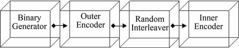
Figure 1. Serial turbo encoder.
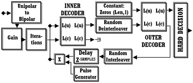
Figure 2. Serial turbo decoder.
inputs to these encoders, are often originated from a binary generator. One encoder accepts the primary data and then using the puncturing technique or a Deinterlacer, it distributes input information between two new outputs providing the systematic (original information stream) and the recursive version (code is generated by a feedback function) of its initial output. The input of the other encoder is an interleaved version of binary generator’s data. Hence it is connected with a puncture block for providing this time only the recursive signal version. Finally the three outputs are joined together using horizontal matrix concatenation followed by transposing and reshaping procedures producing parallel concatenated codes. All the above are presented in Figure 3 constituting a typical PCCC encoder. In Figure 4 is presented the proposed encoder. This encoder is similar to the previous but with an exception. A third convolutional encoder provides another recursive output which is concatenated in parallel with the other three outputs. In turn, this leads to an overall code rate of 1/4 which is different compared to that (1/3) of the typical parallel encoder.
The decoding scheme in the PCCC systems can be considered as a two stages’ procedure. The first stage contains a Unipolar to Bipolar converter, a Gain, and a Zero Order Hold block along with the inverse function of the encoder’s matrix concatenation. The converter and the Gain have the same functionality as in SCCC case. The Zero Order Hold, found in both SCCC and PCCC systems is responsible for setting the number of iterations. Also, the inverse function of matrix concatenation (puncturing) produces the systematic and recursive outputs of convolutional encoders. Then, these signals must be interlaced in order to be driven in the appropriate APP decoders’ inputs. In the proposed system, a similar first stage is also applied before decoders’ section. The differences include more puncturing procedures (as code rate is 1/4) and an additional gain block with the fixed value of 1/2. Generally, the presence of this gain in the design reveals a boosted BER performance. The previous fact has been confirmed through various simulations. The design of the discussed stage appears in Figure 5. The boxes filled with grey color can be added in a standard PCCC system in order to transform it in the proposed one.
Generally, an event’s APP is defined as another event’s function on condition that both events happen simultaneously. Based on this principle, the second part of a Parallel Turbo decoding process [10] includes the A Posteriori Probability (APP) method. The outputs from the first decoding stage are connected to the appropriate inputs as they appear in Figure 6. The interlaced signal coming from OUT 1 is being updated while passes through APP decoder1. Then, for avoiding statistical
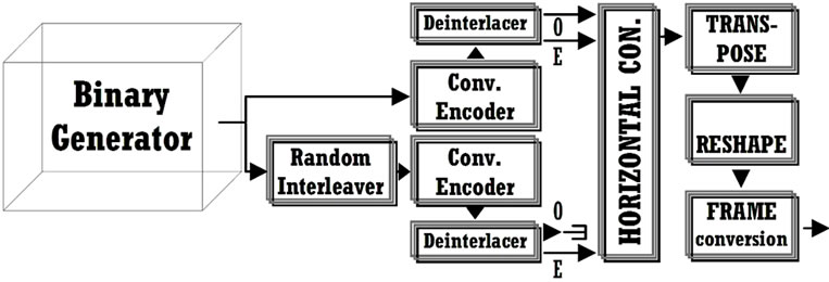
Figure 3. Parallel turbo encoder.
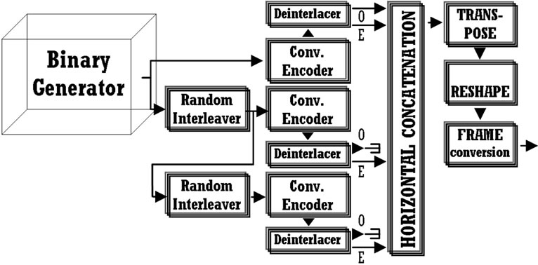
Figure 4. Proposed parallel turbo encoder.
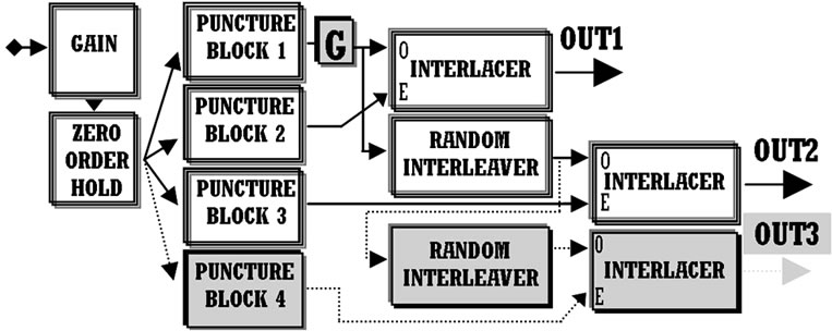
Figure 5. Preliminary stage of PCCC decoding (additional gain is represented by the block labelled as “G”).
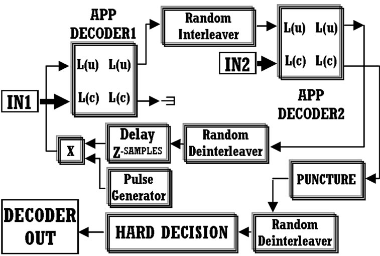
Figure 6. Second stage of parallel turbo decoder.
dependence of the previous data with the data originated from OUT 2, an interleaving process is conducted. The interleaved information along with OUT 2 data passes through a second APP decoder. The signal from its L(u) output is randomly deinterleaved for passing through the feedback section towards the first APP decoder’s L(u). Hence, the L(c) output of the second decoder is punctured [2]. The last procedure will reject data that are no longer needed and in turn this filtered data series will pass through a random deinterleaver. Its output signal is sent to a Hard Decision stage where the determination of type of data (1’s or 0’s) will be conducted. Finally, this data sequence is compared to the primary sequence for calculating the BER performance.
Our Parallel Turbo decoder is consisted of three APP decoders because three data streams from the first stage have to participate in A Posteriori Probability procedures for the proper speculation of the original data sequence. The first APP decoder accepts the interlaced data series from OUT 1. The output of this APP decoder is randomly interleaved for being statistically independent with the interlaced OUT 2 of the first stage. These data sequences pass through APP decoder 2. The only output which is needed is it’s log-likelihoods of code bits L(c) and this is punctured and interleaved for feeding the appropriate data stream in L(u) input of the third decoder. There, the previous stream along with the one coming from OUT 3 is processed for conducting the APP function. One output is needed again as it contains the systematic and recursive output of the encoder. Then, this is punctured in order to be obtained the speculated sequence of primary information. This information passes through two deinterleavers and it reaches Hard Decision block where 1’s and 0’s are produced in order to be compared (in the section of BER calculation) with the original stream of information. Finally, this design along with its iterative function (feedback section is the same with that of the Figure 6) is shown in Figure 7.
3. Simulation Procedures and Results
In this part of the paper, additional details involving the simulation will be provided such as encoding, decoding, puncturing and additive noise characteristics. Moreover, simulation results will be discussed and they involve all systems from Section 2.
The proposed Turbo system was compared to existing systems using PCCC, SCCC or a convolutional encoder (code rate of 1/2). The PCCC encoders (typical and proposed one) are consisted of convolutional encoders with code rate of 1/2 and constraint lengths which are equal to three. The SCCC encoder is consisted from two convolutional encoders. The outer encoder is the same compared to any other convolutional encoder in PCCC design and the inner encoder has a constraint length equal to six. In turn, the overall constraint length equals to seven and code rate to 1/3. In decoders’ section the algorithm that has been set in all APP decoder blocks is max* [11] instead of True A Posteriori Probability [12]. This intentional choice of max* decreases greatly the decoder’s needed memory. Moreover, this decoder’s adjustment simplifies the design while the iterative function and consequently Turbo decoding processes are speeding up. Also, the table (Table 1) of all puncture blocks appears below.
An AWGN channel can be directly associated with the term Eb/No, where Eb is the energy of every transmitted bit of information, and No is the noise power spectral density. Each transmitted symbol can contain a number of information bits. The previous number is relevant each time to the selected modulation type [13]. So, Es (energy per symbol) in relation to Eb appears in Equation (1).
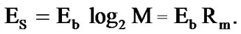 (1)
(1)
Due to the presence of a code rate named Rc, the Es definition must be updated as it shows in Equation (2).
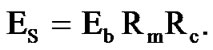 (2)
(2)
The noise variance (σ2 = No/2) is analyzed step by step in Equation (3) in terms of Rm, Rc, Eb/No, Εs and M (constellation size, e.g. for QPSK M = 4).
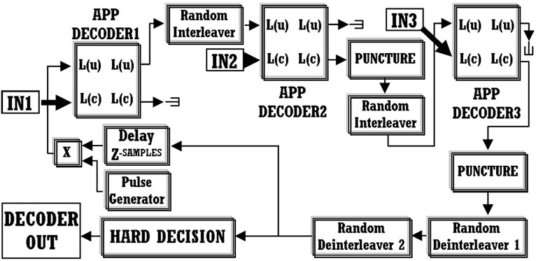
Figure 7. Second stage of proposed parallel turbo decoder.
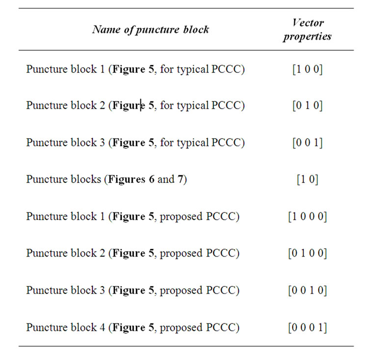
Table 1. Puncture vectors.
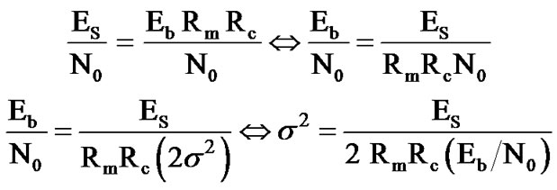 (3)
(3)
Taking into consideration Equation (3), we adjusted noise variance in our simulations, according to each case’s coding rates, and the chosen modulation type of QPSK (with Gray constellation ordering). The utilized noise variances appear in the following table (Table 2).
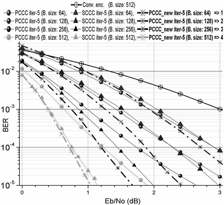
As soon as all parameters adjusted accordingly to all previous key features, the simulations were conducted using various frame sizes (64, 128, 256 and 512). The BER plots in relation to Eb/No for 2, 3 and 5 iterations are presented in Figure 8. The plots are split into four groups with each group corresponding to the appropriate frame size (e.g. group No. 2 in red color represents simulations with frame size 128). So, three sets of simulations are presented here. These are more than adequate for concluding to the necessary results about the behavior of the new encoder-decoder system, as presentation of simulations relevant to 4 iterations and single pass, wouldn’t offer considerably additional knowledge of the new scheme.
Figure 8(a) shows that for block size 64 the behavior of all coding schemes is almost the same to the value of almost 2 dB (Eb/No). From that point and on, the new system appears better compared to all others. From block size 128 to 512 is revealed the innovative performance of the proposed scheme. As an example we could refer to the BER value of 2 × 10⁻⁴ (block size 256) where our system achieves a coding gain of almost 0.2 and 0.3 dB compared to PCCC and SCCC accordingly. Similarly to all other simulations, new PCCC scheme is also better from other Turbo coding techniques and superior to a system with convolutional encoder and viterbi decoder. Hence, it must not be neglected the fact that in many cases the proposed system utilizing a lower block size, outperforms the other schemes with larger block sizes (e.g. in Figure 8(c), the proposed system is better compared to all other schemes. Also, it exhibits an optimum performance for block size 256).
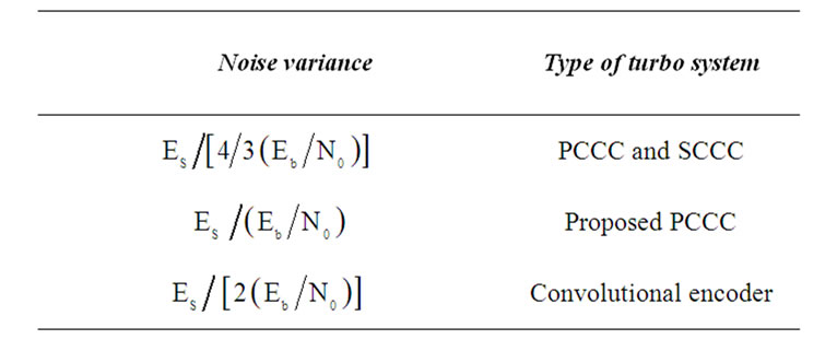
Table 2. Noise variance.
 (a)
(a)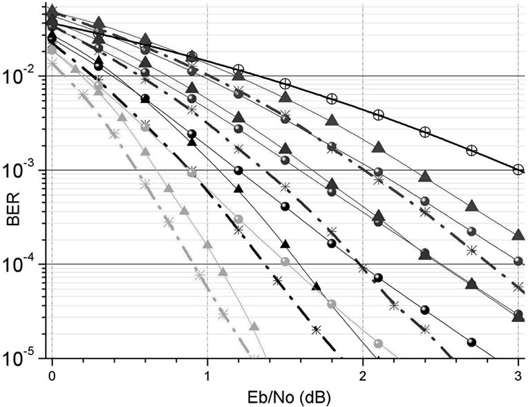 (b)
(b)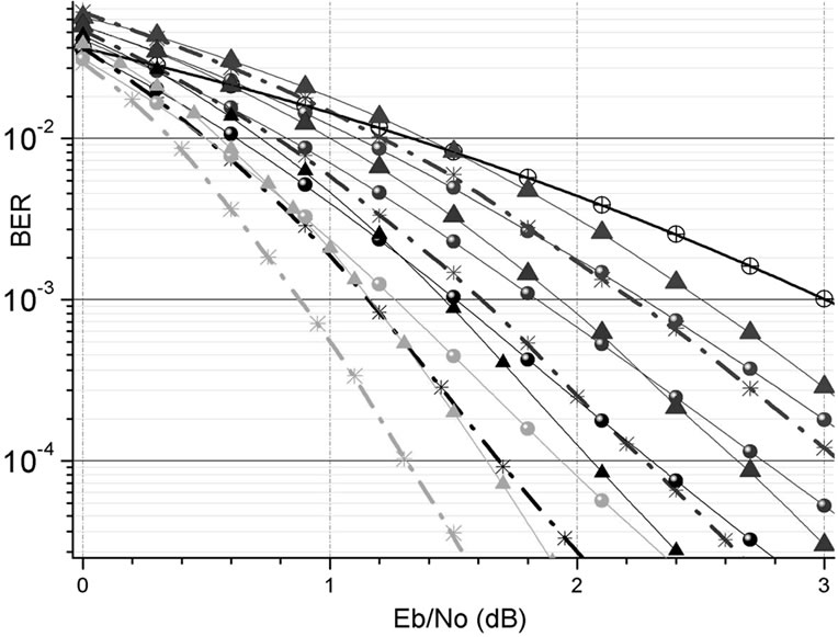 (c)
(c)
Figure 8. BER performance of various coding systems for (a) 5 iterations, (b) 3 iterations and (c) 2 iterations.
4. Conclusions—Future Scopes
The proposed Turbo coding system was described, analyzed and compared to other existing schemes. The purpose of designing this Turbo encoder-decoder was to create a new technique which would be superior for a selected block size and number of iterations every time compared to all other schemes. The number of conducted iterations inside decoder’s section had a maximum value of only five. This is due to the fact that more iterations cause more latency [2]. So, we concluded to design a system, which works well even under the use of a restricted number of feedbacks.
The new PCCC scheme was designed for being part of an OFDM system with enhanced features [5,14]. Also, implementation in a DSP could be possible [15] along with other areas of applications such as fading channels and others [2].
5. Acknowledgements
The research Project is co-funded by the European Union - European Social Fund (ESF) & National Sources, in the framework of the program “HRAKLEITOS II” of the “Operational Program Education and Life Long Learning” of the Hellenic Ministry of Education, Life Long Learning and religious affairs.
6. References
[1] C. Berrou, A. Glavieux and P. Thitimajshima, “Near Shannon Limit Error-Correcting Coding and Decoding: Turbo-Codes. 1,” Proceedings of the IEEE International Conference of Communications ICC 93, IEEE, Geneva, 23-26 May 1993, pp. 1064-1070. doi:10.1109/ICC.1993.397441
[2] S. Choudhury, “Modeling and Simulation of a Turbo Encoder and Decoder for Wireless Communication Systems,” UT Austin, 2002. http://users.ece.utexas.edu/~bevans/courses/ee382c/projects/spring02/index.html
[3] G. Tatsis, C. Votis, V. Raptis, V. Christofilakis, S. K. Chronopoulos and P. Kostarakis, “Performance of UWB-Impulse Radio Receiver Based on Matched Filter Implementation with Imperfect Channel Estimation,” Proceedings of the 7th International Conference of the Balkan Physical Union, American Institute of Physics Conference Series, Vol. 1203, Alexandroupolis, 9-13 September 2009, pp. 573- 578. doi:10.1063/1.3322512
[4] G. Tatsis, C. Votis, V. Raptis, V. Christofilakis, S. K. Chronopoulos and P. Kostarakis, “Design and Implementation of Ultra-Wideband Impulse Radio Transmitter,” Proceedings of the 7th International Conference of the Balkan Physical Union, American Institute of Physics Conference Series, Vol. 1203, Alexandroupolis, 2009, pp. 579-584. doi:10.1063/1.3322513
[5] S. K. Chronopoulos, C. Votis, V. Raptis, G. Tatsis and P. Kostarakis, “In Depth Analysis of Noise Effects in Orthogonal Frequency Division Multiplexing Systems, Utilising a Large Number of Subcarriers,” Proceedings of the 7th International Conference of the Balkan Physical Union, American Institute of Physics Conference Series, Vol. 1203, Alexandroupolis, 9-13 September 2009, pp. 967-972. doi:10.1063/1.3322592
[6] P. Grant, “Turbo Coding,” Connexions, 2009. http://cnx.org/content/m18178/1.3/
[7] S. Rekh, S. S. Rani and A. Shanmugam, “Optimal Choice of Interleaver for Turbo Codes,” Academic Open Internet Journal, Vol. 15, July 2005.
[8] S. Shah and V. Sinha, “Iterative Decoding vs. Viterbi Decoding: A Comparison,” Proceedings of the 14th National Conference on Communications NCCC 2008, IIT Mumbai, 2008, pp. 491-493.
[9] W. Xie, G.-J. Hu and Q. Deng, “Application of Turbo Codes in Optical OFDM Multimode Fiber Communication System,” Optics Communications, Vol. 281, No. 5, 2008, pp. 1118-1122. doi:10.1016/j.optcom.2007.10.84
[10] I. S. Raad and M. Yakan, “Implementation of a Turbo Codes Test Bed in the Simulink Environment,” Proceedings of the 8th International Symposium on Signal Processing and Its Applications ISSPA’05, IEEE, Sydney, 28-31 August 2005, pp. 847-850. doi:10.1109/ISSPA.2005.1581071
[11] A. J. Viterbi, “An Intuitive Justification and a Simplified Implementation of the MAP Decoder for Convolutional Codes,” IEEE Journal on Selected Areas in Communications, Vol. 16, No. 2, February 1998, pp. 260-264. doi:10.1109/49.661114
[12] S. Benedetto, D. Divsalar, G. Montorsi and F. Pollara, “A Soft-Input Soft-Output Maximum A Posterior (MAP) Module to Decode Parallel and Serial Concatenated Codes,” TDA Progress Report, Jet Propulsion Laboratory, California Institute of Technology, Vol. 42-127, 1996.
[13] P. G. M. de Bot, “Design of a Digital Communication System Using Multistage Block Coded Modulation,” Technical Report, Technische Universiteit Eindhoven, Eindhoven, 1991.
[14] S. K. Chronopoulos, G. Tatsis, V. Raptis and P. Kostarakis, “Enhanced PAPR in OFDM without Deteriorating BER Performance,” International Journal of Communications, Network and System Sciences, Vol. 4, No. 3, March 2011, pp. 164-169. doi:10.4236/ijcns.2011.43020
[15] M. F. Sabir, R. Tripathi, B. L. Evans and A. C. Bovik, “A Real-Time Embedded Software Implementation of a Turbo Encoder and Soft Output Viterbi Algorithm Based Turbo Decoder,” Record of the 36th ACSC, IEEE, November 2002, pp. 1099-1103. doi:10.1109/ACSSC.2002.1196954