World Journal of Condensed Matter Physics
Vol.4 No.3(2014), Article ID:49394,12 pages
DOI:10.4236/wjcmp.2014.43019
Hole-Pair Formation in Cuprate Superconductors despite Antiferromagnetic Fluctuations
Rana Janardon Singh1, Shakeel Khan2
1Physics Department, Aligarh Muslim University, Aligarh, India
2Department of Applied Physics, Aligarh Muslim University, Aligarh, India
Email: ranajsingh@yahoo.com, skhanapd@gmail.com
Copyright © 2014 by authors and Scientific Research Publishing Inc.
This work is licensed under the Creative Commons Attribution International License (CC BY).
http://creativecommons.org/licenses/by/4.0/


Received 1 May 2014; revised 13 June 2014; accepted 28 June 2014
ABSTRACT
We have earlier proposed models of preformed hole pairs based on the results of
our electron paramagnetic resonance experiments. A hole doped in a cuprate superconductor
causes ferromagnetic alignment of the spins of the holes of 4 Cu2+ ions
of the plaquette (CuO)4 in which it enters. Spin alignments undergo oscillations
from vertically upward to vertically downward of the CuO2 plane. Vertical
projections of spins go on changing when they pass through different plaquettes
going to zero when they pass through the CuO2 plane. Ferromagnetic alignments
of spins produce magnetic fields on the plane proportional to their vertical projections.
When two holes travelling in CuO2 plane come across each other at a certain
distance between them, they are attracted towards each other by Heisenberg exchange
interaction and their path is decided by the magnetic field produced due to spin
alignments. Their path is similar to
 atomic orbital. Y-123 has been chosen as an example. Due to plethora of evidence
of antiferromagnetic fluctuations in cuprates, hole-pair formation has been tried
in Y-123 assuming antiferromagnetic fluctuations in it. It has been found that hole-pair
formation in spite of AFM fluctuations can be explained on the same lines as done
earlier. Hole-pair formation was tried in Tl-2201 to test whether the same rules
apply in cuprates with very high coherence lengths. Coherence length in Tl-2201
= 52 Å, whereas in Y-123 = 15 - 20 Å in CuO2 plane. It has
been reported that in Tl-2201 the CuO2 plane is very flat and smooth.
From this it was concluded that high coherence length is the result of the smoothness
of the plane. Further it was concluded that the smoothness of the CuO2
plane depends upon the nature of the near neighbors of the CuO2 plane.
Near neighbors of Y-123 and Tl-2201 have been compared.
atomic orbital. Y-123 has been chosen as an example. Due to plethora of evidence
of antiferromagnetic fluctuations in cuprates, hole-pair formation has been tried
in Y-123 assuming antiferromagnetic fluctuations in it. It has been found that hole-pair
formation in spite of AFM fluctuations can be explained on the same lines as done
earlier. Hole-pair formation was tried in Tl-2201 to test whether the same rules
apply in cuprates with very high coherence lengths. Coherence length in Tl-2201
= 52 Å, whereas in Y-123 = 15 - 20 Å in CuO2 plane. It has
been reported that in Tl-2201 the CuO2 plane is very flat and smooth.
From this it was concluded that high coherence length is the result of the smoothness
of the plane. Further it was concluded that the smoothness of the CuO2
plane depends upon the nature of the near neighbors of the CuO2 plane.
Near neighbors of Y-123 and Tl-2201 have been compared.
Keywords:Hole-Pair Formation in Cuprate Superconductors, Buckling
Angle in CuO2 Plane, Coherence Length in a-b-Plane


1. Introduction
@NolistTemp# In the absence of consensus regarding the mechanism
of superconductivity in cuprates, people are thinking of preformed hole-pairs [1] [2] which
below a certain temperature undergo Bose-Einstein condensation and cause superconductivity.
We have proposed models of preformed hole-pairs [3]
-[5] for resistanceless current flow in the a-b
plane and along c-axis of cuprate superconductors. For better understanding of this
paper, it should be read in conjunction with the paper in Ref.
[4] because the detailed treatment given in
[4] cannot be reproduced here. However, some salient points
of the paper [4] are given here which
may be of help to readers. As prepared, cuprate superconductors are electron paramagnetic
resonance (EPR) silent because of antiferromagnetic (AFM) coupling of Cu2+
ions in the all-important CuO2 plane. When cuprate superconductors are
deoxygenated, they show EPR spectra of Cu-monomer, dimmer, tetramer and octamer,
but more frequently (CuO)4 tetramer. (CuO)4 tetramer is the
unit cell of two-dimensional (2-D) CuO2 plane and by understanding its
properties, one can understand the properties of CuO2 plane which is
the seat of superconductivity. Spectra of (CuO)4 and other fragments
[6] -[13] given
above are observed also in constituents of superconductors as BaCuO2,
SrCuO2, CaCuO2, Bi2CuO4, CuO etc. On
deoxygenation, (CuO)4 unit gets magnetically isolated from the bulk by
breaking 8 Cu-O bonds situated at its 4 corners. In [14]
, it has been found that Cu-O bonds are
 ionic and
 covalent. Breaking of 8 bonds amounts to loss of one electron from the (CuO)4
plaquette, because oxygen is more electronegative than copper. Loss of one electron
means the introduction of one hole in the (CuO)4 plaquette. This situation
can be represented by the following equation. An isolated (CuO)4 unit
covalent. Breaking of 8 bonds amounts to loss of one electron from the (CuO)4
plaquette, because oxygen is more electronegative than copper. Loss of one electron
means the introduction of one hole in the (CuO)4 plaquette. This situation
can be represented by the following equation. An isolated (CuO)4 unit
 (CuO)4 unit of continuous sheet of CuO2 plane + a hole inside
it. Observation of 4 fine structure signals which corresponds to total electronic
spin
(CuO)4 unit of continuous sheet of CuO2 plane + a hole inside
it. Observation of 4 fine structure signals which corresponds to total electronic
spin
 and 13 components in each fine structure line which corresponds to total nuclear
spin
and 13 components in each fine structure line which corresponds to total nuclear
spin
 suggest that advent of a hole in a (CuO)4 entity causes ferromagnetic
(FM) coupling of spins of 4 Cu2+ ions resulting into total electronic
spin
suggest that advent of a hole in a (CuO)4 entity causes ferromagnetic
(FM) coupling of spins of 4 Cu2+ ions resulting into total electronic
spin
 and 13 hyperfine components in each fine structure signal suggest that the advent
of the hole in (CuO)4 entity causes 4 holes of the 4 Cu2+
ions tocirculate around the (CuO)4 framework and each hole comes into
contact with all 4 Cu2+ ions. As discussed above, on introduction of
a hole in a (CuO)4 plaquette, spins of all 4 Cu2+ ions align
ferromagnetically and should continue to fluctuate with the same frequency corresponding
to 41 meV antiferromagnetic signal seen in Y-123 which we have chosen as an example.
41 meV equated to hν gives
and 13 hyperfine components in each fine structure signal suggest that the advent
of the hole in (CuO)4 entity causes 4 holes of the 4 Cu2+
ions tocirculate around the (CuO)4 framework and each hole comes into
contact with all 4 Cu2+ ions. As discussed above, on introduction of
a hole in a (CuO)4 plaquette, spins of all 4 Cu2+ ions align
ferromagnetically and should continue to fluctuate with the same frequency corresponding
to 41 meV antiferromagnetic signal seen in Y-123 which we have chosen as an example.
41 meV equated to hν gives
 to be equal to
 hertz or time-period
 sec. But the question will be in which direction? It has been noted in [1] that modest magnetic field when it is perpendicular
to CuO2 plane suppresses AFM resonance in YBa2Cu3O6.6
more significantly than when applied horizontally. It suggests that the FM coupled
spins of holes of 4 Cu2+ ions fluctuate vertically above and below the
CuO2 plane. Starting from a position where FM aligned spins stand vertically
upward of the CuO2 plane, they have maximum resultant spin angular momentum.
When they cross CuO2 plane, spins find themselves spread in CuO2
plane. The diagonally opposite ones directed in opposite directions with resultant
spin angular momentum equal to zero after a time
sec. But the question will be in which direction? It has been noted in [1] that modest magnetic field when it is perpendicular
to CuO2 plane suppresses AFM resonance in YBa2Cu3O6.6
more significantly than when applied horizontally. It suggests that the FM coupled
spins of holes of 4 Cu2+ ions fluctuate vertically above and below the
CuO2 plane. Starting from a position where FM aligned spins stand vertically
upward of the CuO2 plane, they have maximum resultant spin angular momentum.
When they cross CuO2 plane, spins find themselves spread in CuO2
plane. The diagonally opposite ones directed in opposite directions with resultant
spin angular momentum equal to zero after a time . After next
 , they get FM
aligned vertically downward of the CuO2 plane; after another
, they get FM
aligned vertically downward of the CuO2 plane; after another , the yagain find
themselves spread in CuO2 plane with zero spin angular momentum. Yet
after another
, the yagain find
themselves spread in CuO2 plane with zero spin angular momentum. Yet
after another , they go back to
the original positions or vertically aligned above the CuO2 plane. The
alignment of spins of Cu2+ holes and their circulation around the (CuO)4
plaquette produce magnetic field on the CuO2 plane in proportion to resultant
spin angular momentum and locations of holes during their circulation. The magnetic
field produced has been calculated [4]
to vary from
, they go back to
the original positions or vertically aligned above the CuO2 plane. The
alignment of spins of Cu2+ holes and their circulation around the (CuO)4
plaquette produce magnetic field on the CuO2 plane in proportion to resultant
spin angular momentum and locations of holes during their circulation. The magnetic
field produced has been calculated [4]
to vary from
 gauss. When 2 holes wandering in the CuO2 sheet of a superconductor come
across a column or row of (CuO)4 plaquettes within a certain distance,
they are attracted towards each other by Heisenberrg exchange interaction and follow
a path guided by the exchange interaction between them and magnetic field generated
by the directions of spins of Cu2+ holes and their locations during circulation
around a (CuO)4 plaquette in which they are situated at that instant.
The path executed by the pair of holes is similar to
gauss. When 2 holes wandering in the CuO2 sheet of a superconductor come
across a column or row of (CuO)4 plaquettes within a certain distance,
they are attracted towards each other by Heisenberrg exchange interaction and follow
a path guided by the exchange interaction between them and magnetic field generated
by the directions of spins of Cu2+ holes and their locations during circulation
around a (CuO)4 plaquette in which they are situated at that instant.
The path executed by the pair of holes is similar to
 atomic orbital which has been supported by many theories and experiments. The wandering
hole hops from one oxygen ion to the other forcing the holes of Cu2+
ions to circulate along the periphery of the (CuO)4 plaquette. The spin
angular momentum of wandering hole does not combine with spin or angular momentum
of Cu2+ holes. To avoid confusion, let it be clear that the holes wandering
in the CuO2 plane due to doping will be called wandering holes and those
associated with Cu2+ ions will be called Cu2+ holes.
atomic orbital which has been supported by many theories and experiments. The wandering
hole hops from one oxygen ion to the other forcing the holes of Cu2+
ions to circulate along the periphery of the (CuO)4 plaquette. The spin
angular momentum of wandering hole does not combine with spin or angular momentum
of Cu2+ holes. To avoid confusion, let it be clear that the holes wandering
in the CuO2 plane due to doping will be called wandering holes and those
associated with Cu2+ ions will be called Cu2+ holes.
2. Formation of Hole-Pairs
A brief description of hole-pair formation is given below. Mathematical treatment of hole-pair formation in cuprates has been given in [4] . The shape of the hole-pair has been shown in figure 3 of [4] . This figure has been reproduced in this paper as figure 1. Full mathematics is avoided here, but some portions are explained here which will be of help in grasping the main idea and final equation describing the order parameter. Application of the equation in describing the shape of the hole-pair has been shown through a shortened table which is a part of table 1 in [4] . The shortened table is numbered 1 in this paper.
In figure 1, the squares A, B, C, D, E, F, G. H. I are the unit cells of CuO2 2-D plane, each taken to be a square of side 38.4 Å, which is one side of a plaqette in a representative Y-123 superconductor (though in actual case there is a very small difference between a and b sides). When 2 wandering holes enter figure 1, Hole 1 from A side and Hole 2 from E side, they move towards each other under the effect of Heisenberg exchange interaction. Their velocities are modified by the magnetic field present in each (CuO)4 plaquette they traverse.
Here we will explain some symbols and terms and the final equation which determines the path of holes in the preformed hole-pairs. Table 1 in this paper which shows position of holes at different angles along their paths in figure 1 will be discussed for further clarification.
The velocity of a charged particle (here hole) does not change by magnetic field;
only its direction is changed and
 is always equal to
 . Motion of charged particle
of charge “
. Motion of charged particle
of charge “ ” in
” in
 -plane under the action of magnetic field
 (in
(in
 -direction) is given by the following equations:
 (1)
(1)
 (2)
(2)
 (3)
(3)
where
 is the mass of the charged particle. Equation (3) goes to zero and need not be considered
further.
is the mass of the charged particle. Equation (3) goes to zero and need not be considered
further.
In the above equations, the three quantities ,
,
 and
and
 have been used in the following forms:
 ;
; ;
; , because magnitude
of these quantities depends on the positions of holes in the figure which depends
on the angle ωt.
, because magnitude
of these quantities depends on the positions of holes in the figure which depends
on the angle ωt.
 has been expressed as
 with a negative sign, because in this problem, the origin has been chosen at the
center of the cell A and for all positions of the holes except at the origin,
with a negative sign, because in this problem, the origin has been chosen at the
center of the cell A and for all positions of the holes except at the origin,
 -coordinate is always negative.
For angular velocities also, two notations have been used:
 and
and .
.
 corresponds to the Euclidean angle according to
which the total angle in going round a circle is
corresponds to the Euclidean angle according to
which the total angle in going round a circle is
 or
or
 .But for the spins of Cu2+ holes, one oscillation is completed
for Hole 1 in going from A to E and for Hole 2 in going from E to A. Both these
angles are equal to 180˚ according to Euclidean geometry. This is why on the
circumference of the circle in figure 1, both the
angles,
.But for the spins of Cu2+ holes, one oscillation is completed
for Hole 1 in going from A to E and for Hole 2 in going from E to A. Both these
angles are equal to 180˚ according to Euclidean geometry. This is why on the
circumference of the circle in figure 1, both the
angles,
 and ω have been shown. It means that
 . With this much introduction,
it will be easy to appreciate the full meaning of the final formula in Ref.
[4] defining
the positions of holes at different angles as shown in
figure 1. The final formula in
[4] is shown below and in this paper, it is numbered
4.
. With this much introduction,
it will be easy to appreciate the full meaning of the final formula in Ref.
[4] defining
the positions of holes at different angles as shown in
figure 1. The final formula in
[4] is shown below and in this paper, it is numbered
4.
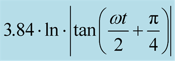
 (4)
(4)
In equation (4),
 is some length used for plotting this equation.
 has been given a nominal value of 7.68 Å, which is twice
the side (38.4 Å) of the unit cell of 2-dimensional CuO2 plane
of Y-123 superconductor. The R.H.S. of Equation (4) indicates the position of a
wandering hole at an angle
has been given a nominal value of 7.68 Å, which is twice
the side (38.4 Å) of the unit cell of 2-dimensional CuO2 plane
of Y-123 superconductor. The R.H.S. of Equation (4) indicates the position of a
wandering hole at an angle . The magnitude of the R.H.S. of
Equation (4) is shown by a straight line from the coordinate of the angle
. The magnitude of the R.H.S. of
Equation (4) is shown by a straight line from the coordinate of the angle
 on the circumference of
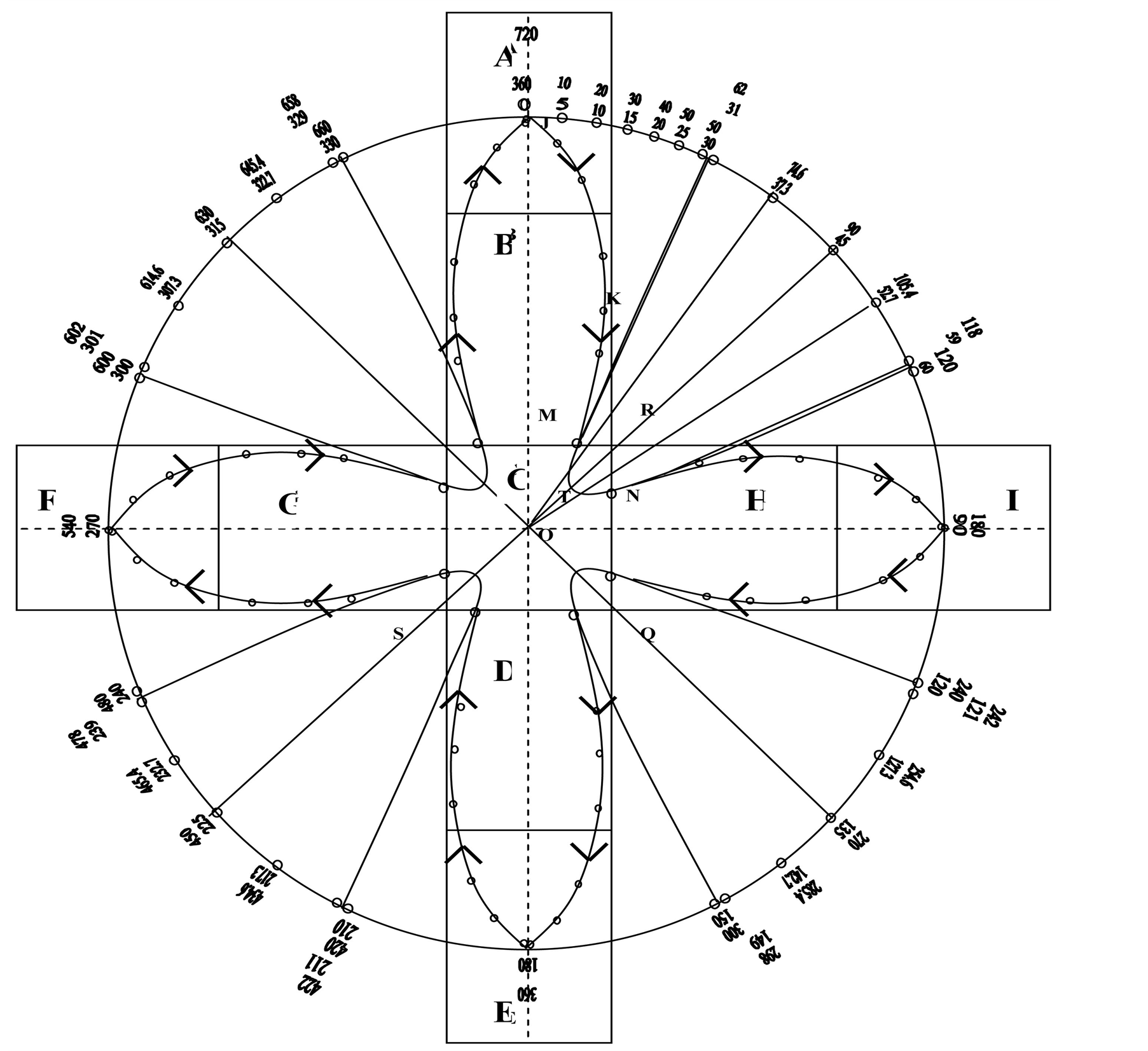
Figure 1. Formation of hole-pairs, both the holes traverse the same path continuously.
the circle towards the center of the circle. The tips at the end of lines (shown
by dots) represent the positions of wandering holes. The magnitudes of the R.H.S.
of Equation (4) for angles varying from
 to
to
 have been given in Table1 In the range of angles
 to
to
 all the values are positive, but in the range
 to
to
 all the values are negative. But in the range of
 to
to , the direction of the magnetic field is also negative,
that is , downward of the CuO2 plane, whereas in the range
, the direction of the magnetic field is also negative,
that is , downward of the CuO2 plane, whereas in the range
 to
to , it is upward of the CuO2 plane. In
Equation (4) also, there is ± sign. It means in both ranges, the holes are attracted
towards the center of the circle or the center of the cell C. With the help of Table 1 and figure 1,
meaning of the Equation (4) can be understood. So far discussion has been mainly
for Hole 1. But same is true for Hole 2 which starts from E and completes
, it is upward of the CuO2 plane. In
Equation (4) also, there is ± sign. It means in both ranges, the holes are attracted
towards the center of the circle or the center of the cell C. With the help of Table 1 and figure 1,
meaning of the Equation (4) can be understood. So far discussion has been mainly
for Hole 1. But same is true for Hole 2 which starts from E and completes
 of journey (
 to
to ). In
figure 1, Holes 1 and 2 always occupy positions diagrammatically
opposite to each other.
). In
figure 1, Holes 1 and 2 always occupy positions diagrammatically
opposite to each other.
Going through Table 1, one finds that at certain
angles
 the position of Hole 1 lies beyond the cell C. From
 , the position of Hole
1 lies beyond the cell C. At
, the position of Hole
1 lies beyond the cell C. At
 the position of Hole 1 is indeterminate according to Equation (4) or effectively
very far from the cell C. At
the position of Hole 1 is indeterminate according to Equation (4) or effectively
very far from the cell C. At , the position of Hole
1 is just at the center of the cell C. The position of Hole 2 at
, the position of Hole
1 is just at the center of the cell C. The position of Hole 2 at
 is also at the center of the cell C. Two holes cannot
be present at the same place at the same time. Due to Coulomb repulsion, they cannot
come very near to each other in the cell C.
is also at the center of the cell C. Two holes cannot
be present at the same place at the same time. Due to Coulomb repulsion, they cannot
come very near to each other in the cell C.
Hole 1 remains inside the cell C within angles . Similarly Hole 2 remains
inside the cell
. Similarly Hole 2 remains
inside the cell

Table 1 .
 angle which the spin vector of the hole makes with a direction
perpendicular to the CuO2 plane. In the rotation of
angle which the spin vector of the hole makes with a direction
perpendicular to the CuO2 plane. In the rotation of
 in the Cartesian system, the spin vector completes two oscillations and so ωt varies
from
in the Cartesian system, the spin vector completes two oscillations and so ωt varies
from
 The expression
 gives the position of the hole at the angle ωt in the (3).
Table 2 .Showing positions of holes in different (CuO)4 plaquette or cells, no. of cells in FM or half FM coupling and no. of cells in AFM coupling.
C within angles . Inside the cell C, holes
repel each other, their velocities are reduced and Heisenberg exchange interaction
becomes ineffective due to such a small separation between the two charged particles.
From the cell C, Hole 1 is deflected towards cells H-I and Hole 2 towards the cells
G-F. When Hole 1 reaches cell I and Hole 2 reaches cell F, they experience maximum
magnetic field because of vertical alignment of all the 4 Cu2+ spins
in respective cells. They are turned back from these cells due to magnetic mirror
effect. Just to refresh memory, magnetic mirror effect is that force that causes
the ions in the ionosphere to oscillate between the north pole and the south pole
of the earth due to highest strength of the magnetic field at the two poles. The
path of both the holes has been shown in figure 1.
The holes are indistinguishable and both holes follow the path A-C-I-C-E-C-F-C-A.
Ultimately they circulate along a path similar to the shape of the atomic orbital
. Inside the cell C, holes
repel each other, their velocities are reduced and Heisenberg exchange interaction
becomes ineffective due to such a small separation between the two charged particles.
From the cell C, Hole 1 is deflected towards cells H-I and Hole 2 towards the cells
G-F. When Hole 1 reaches cell I and Hole 2 reaches cell F, they experience maximum
magnetic field because of vertical alignment of all the 4 Cu2+ spins
in respective cells. They are turned back from these cells due to magnetic mirror
effect. Just to refresh memory, magnetic mirror effect is that force that causes
the ions in the ionosphere to oscillate between the north pole and the south pole
of the earth due to highest strength of the magnetic field at the two poles. The
path of both the holes has been shown in figure 1.
The holes are indistinguishable and both holes follow the path A-C-I-C-E-C-F-C-A.
Ultimately they circulate along a path similar to the shape of the atomic orbital . Complete derivation of Equation (4) has been given
in
. Complete derivation of Equation (4) has been given
in
[4] .
3. Hole-Pair Formation in Spite of Antiferromagnetic Fluctuations
It has been observed that in high
 cuprate superconductors [15] -[22] and in heavy Fermion systems (UPd2Al3,
CeCoIn5) [23]
[24] and also in iron oxide superconductor (Ba0.6K0.4Fe2As2)
[25] , inelastic neutron scattering exhibit AFM
fluctuations dominated by a resonance signal in single layered CuO2 superconductors
[21] [22]
, there appears only one resonant signal; in two-layered superconductors [15] -[20] , two signals
are observed of odd and even parity where the modes differ in symmetry with respect
to exchange between adjacent CuO2 layers. Odd parity signal which is
resonance signal is stronger and occurs at smaller energy and the even parity signal
is weaker and occurs at higher energy. A universal relation between AFM resonance
signal and superconducting gap
cuprate superconductors [15] -[22] and in heavy Fermion systems (UPd2Al3,
CeCoIn5) [23]
[24] and also in iron oxide superconductor (Ba0.6K0.4Fe2As2)
[25] , inelastic neutron scattering exhibit AFM
fluctuations dominated by a resonance signal in single layered CuO2 superconductors
[21] [22]
, there appears only one resonant signal; in two-layered superconductors [15] -[20] , two signals
are observed of odd and even parity where the modes differ in symmetry with respect
to exchange between adjacent CuO2 layers. Odd parity signal which is
resonance signal is stronger and occurs at smaller energy and the even parity signal
is weaker and occurs at higher energy. A universal relation between AFM resonance
signal and superconducting gap
 has been demonstrated according to which energy of resonance signal
 is proportional to 2∆, but always less than
 [26] . McDonald et al.
[27] have pointed out that the experimentally determined Cooper pair wave
function in cupratesmaps directly on the spin fluctuation disturbance responsible
for the AFM peaks measured in inelastic neutron scattering. Large number of works
cited above showing AFM excitations, commensurate or incommensurate suggest that
these fluctuations are intrinsic property of cuprate superconductors and so should
be integral part of any theory. But these fluctuations have failed to explain superconductivity.
[26] . McDonald et al.
[27] have pointed out that the experimentally determined Cooper pair wave
function in cupratesmaps directly on the spin fluctuation disturbance responsible
for the AFM peaks measured in inelastic neutron scattering. Large number of works
cited above showing AFM excitations, commensurate or incommensurate suggest that
these fluctuations are intrinsic property of cuprate superconductors and so should
be integral part of any theory. But these fluctuations have failed to explain superconductivity.
3.1. Degree of Antiferromagnetism and Ferromagnetism with Doping Level
Kopp et al., [28] noted that any trace of AFM fluctuation is absent in over doped regime of cuprates. Superconductivity arises in Mott insulators after doping level of nearly 5%; attains optimal value at 16%; overdoping starts at 19% and the superconducting dome terminates in the vicinity of 25%. In the overdoped regime, spin susceptibility shows a ferromagnetic upturn. He also suggested that at the end of superconductivity dome, there should be genuine ferromagnetism at zero temperature. Sonier et al. [29] observed gradual disappearance of antiferromagnetism on doping of cuprates and onset of static magnetic order in the highly doped regimes. But this magnetism is not of long range order but magnetic moments appear in dilute form. The main point in [28] [29] is that charge doping or hole-doping induces FM order in cuprates and competing ferromagnetic fluctuations are simultaneously present with superconductivity. It has also been concluded that on increasing doping level upto 25%, ferromagnetic fluctuations increase at the expense of antiferromagnetic fluctuations.
3.2. EPR Signals Due to Ferromagnetism though Experimentally Only Antiferromagnetic Fluctuations Are Observed
We have proposed models of preformed hole-pairs in cuprates [3] -[5] on the basis of FM spin fluctuation in (CuO)4 plaquette of CuO2 plane, but there is plethora of evidence that AFM fluctuations are intrinsic properties of cuprates. We will now show that hole-pairs can be formed on the same lines as done earlier without consideration of AFM fluctuations. For this, let us consider only A, B, C cells of figure 1, shown separately in figure 2.
We will consider the behaviour of Hole 1 only and the same applies to Hole 2. When the hole1 enters cell A of figure 2, the spins of all the 4 Cu2+ ions at its corners align vertically above the CuO2 plane as has been concluded from our EPR experiments and has been used in the formation of hole-pairs in figure 1. It is to be remembered from figure 1 that when a hole goes from cell A to B and then to C, the vertical components of spins gradually decrease and so also the magnetic field produced from them. Presently we are concerned with the states of spins 3, 4, 5, 6 when Hole 1 enters B from A. The spins 3 and 4 will remain in ferromagnetic alignment, but their spins will be tilted from the vertical direction in direct proportion to the fraction of time-period T of spin fluctuation spent by the hole in coming from A to B cell. But what about the spins numbered 5 and 6.Will there be FM exchange between the pair of spins 3 and 4 and the pair of 5 and 6 spins or AFM exchange. But because there is a hole present in the cell B [28] [29] which cause FM alignment of spins in any cell, so all the 4 spins 3, 4, 5, 6 will be in FM arrangement, but all 4 of them more inclined towards the horizontal plane. When the hole reaches the cell C, there will be again realignment of spins with decreased vertical component. When the hole reaches the center of the cell C, the total vertical component will be zero. As has been discussed in the hole-pair formation in figure 1, the hole will never reach the center of the cell C, because at the same time the other partner of the hole pair would also reach the center of the cell C which is not possible because of the Coulomb repulsion between the holes. Thus the whole process of hole-pair formation is in the same way as in the formation of hole-pair described in figure 1.
But here a question arises, why in neutron diffraction experiments on cuprate superconductors,
only AFM fluctuations are observed and not FM fluctuations. To answer this question,
let us calculate the percentages of FM and AFM alignments of spins during one time-period
 of journey of Holes 1 and 2 in figure 1. The calculation
of FM and AFM order can be done under 2 assumptions: 1) in whichever 2 cells out
of the 9 cells the 2 holes are present, they will be in FM alignment and the rest
7 in AFM alignment. In this way, during one time-period
of journey of Holes 1 and 2 in figure 1. The calculation
of FM and AFM order can be done under 2 assumptions: 1) in whichever 2 cells out
of the 9 cells the 2 holes are present, they will be in FM alignment and the rest
7 in AFM alignment. In this way, during one time-period
 of journey of two holes in figure 1,
 will be in FM order and
 in AFM order.
Under the assumption (2) when Holes 1 and 2 are in cells A and E respectively in the beginning, there will be FM order in cells A and E and in the rest 7, AFM order. When Hole 1 enters cell B and Hole 2 enters cell D, there will be subdued FM order in cells A and B due to Hole 1 and in cells E and D due to Hole 2, because there is common boundary between A and B for Hole 1 and common boundary between E and D for Hole
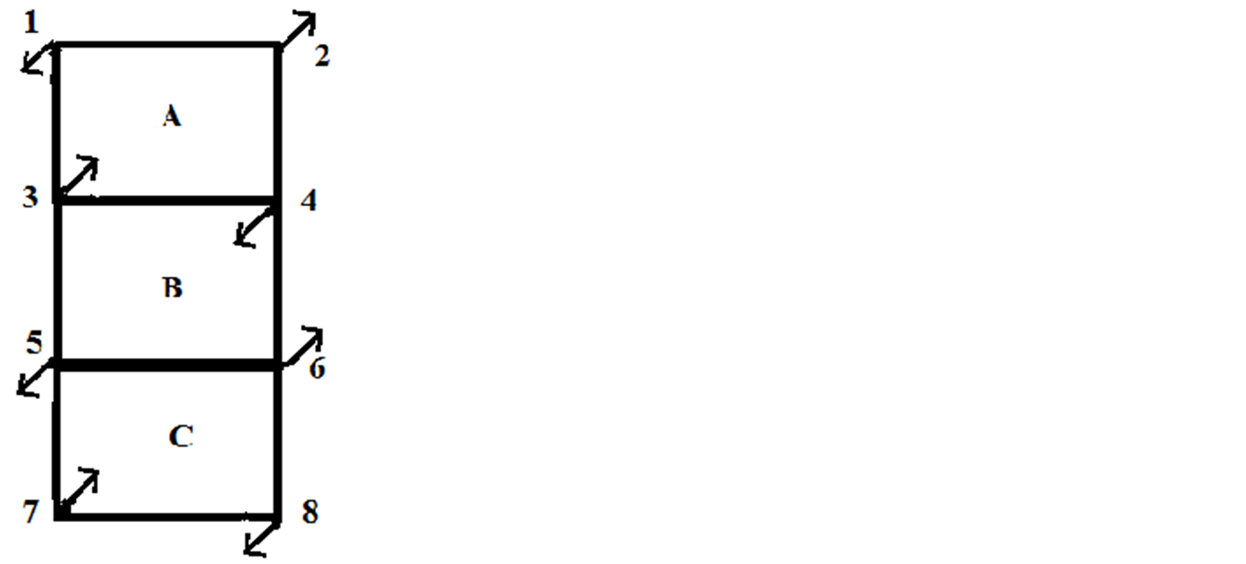
Figure 2. Showing spin configuration in AFM alignment. Spins have been numbered.
2. It can be said that there is half FM order both in A and B due to Hole 1 and half FM order both in D and E due to Hole 2. Half FM order is justified, because when both the holes enter cell C, FM order is nearly lost. It can be said that full ferromagnetism is due to the hole1 while in A and no ferromagnetism while in C. Thus when Hole 1 has reached cell B from A, it can be appropriately said that in both cells there is ferromagnetism of half strength only. From the cell C, due to curvature of the paths of holes and Coulomb repulsion, Hole 1 is reflected towards cells H-I and Hole 2 towards G-F. When Holes 1 and 2 reach cell H and G respectively, half FM order is attained, but FM order is built downward of the CuO2 plane. When Holes 1 and 2 reach I and F cells respectively, there will be full FM order downward of the CuO2 plane. When the holes turn back from the cells I and F at the extreme ends, they enter cells H and G respectively, half FM order is obtained in cells I and H due to Hole 1 and in cells F and G due to Hole 2. Again both the holes reach cell C, where there will be negligible or zero magnetic order. From there, Hole 1 will be reflected towards cells D-E and Hole 2 towards cells B-A with the same type of magnetic order as in going from cell C towards cells H-I for the Hole 1 and towards G-F for Hole 2, but FM order now building upward of the CuO2 plane. When Hole 1 has reached cell E and Hole 2 cell A, full FM order will be attained and by this time their journey in one time-period T has been completed. Thereafter they will be following the same path repeatedly.
Calculations by the first assumption gives
 percent of cells in FM spin alignment and
 percent in AFM alignment. Calculation by the second method gives 16% FM order and
 AFM order. Calculation of FM and AFM orders have been shown in
table 2. Ratio of FM order to AFM order
AFM order. Calculation of FM and AFM orders have been shown in
table 2. Ratio of FM order to AFM order . Calculation from
the second assumption is more realistic. But the above calculations have been done
in the most favourable case where at all the possible places of hole-pair formation,
holes are present. In actual cases (from underdoped to optimum doped), there will
be many patches where hole-pairs would not have been formed because no holes are
available. Because of the small percentage of FM alignment in comparison to AFM
alignment, the former may be submerged under AFM alignment in actual experiments.
AFM coupling of spins of holes of Cu2+ spins is unable to explain superconductivity.
But FM coupling of Cu2+ spins can explain superconductivity [4] but not supported by neutron scattering experiments.
The reason may be that under overwhelming AFM order, minority transitory FM order
is submerged. The present mechanism of hole-pair formation is supported by theoretical
considerations [4] and cannot be rejected
by experiments because of its indetectibility of FM order due to its lean and fleeting
presence. Time-period of a hole in Y-123 is
. Calculation from
the second assumption is more realistic. But the above calculations have been done
in the most favourable case where at all the possible places of hole-pair formation,
holes are present. In actual cases (from underdoped to optimum doped), there will
be many patches where hole-pairs would not have been formed because no holes are
available. Because of the small percentage of FM alignment in comparison to AFM
alignment, the former may be submerged under AFM alignment in actual experiments.
AFM coupling of spins of holes of Cu2+ spins is unable to explain superconductivity.
But FM coupling of Cu2+ spins can explain superconductivity [4] but not supported by neutron scattering experiments.
The reason may be that under overwhelming AFM order, minority transitory FM order
is submerged. The present mechanism of hole-pair formation is supported by theoretical
considerations [4] and cannot be rejected
by experiments because of its indetectibility of FM order due to its lean and fleeting
presence. Time-period of a hole in Y-123 is . And in this time a hole
has to cross 10 cells (not only 9 cells but 10 cells because C cell will come twice
in its path). Time spent in C cell will be greater than in any other cell, because
in this cell both of the holes face Coulomb repulsion and their velocities are reduced
and practically there is no magnetic order in this cell. So a hole has to pass through
8 cells only with some kind of FM order and it will take less than
. And in this time a hole
has to cross 10 cells (not only 9 cells but 10 cells because C cell will come twice
in its path). Time spent in C cell will be greater than in any other cell, because
in this cell both of the holes face Coulomb repulsion and their velocities are reduced
and practically there is no magnetic order in this cell. So a hole has to pass through
8 cells only with some kind of FM order and it will take less than
 per cell. There is another reason for FM order not to be observed in experiments
is that half of time, projections of holes will be above the plane and half of time
below the plane. They may cancel each other because changeover is very fast. It
may be possible that the transitory FM order in such a shot spell is not detected
in neutron scattering experiments. Kopp et al. [28]
and Sonier et al. [29] have maintained
that in superconductivity dome in the phase diagram, FM order coexists with AFM
order.
per cell. There is another reason for FM order not to be observed in experiments
is that half of time, projections of holes will be above the plane and half of time
below the plane. They may cancel each other because changeover is very fast. It
may be possible that the transitory FM order in such a shot spell is not detected
in neutron scattering experiments. Kopp et al. [28]
and Sonier et al. [29] have maintained
that in superconductivity dome in the phase diagram, FM order coexists with AFM
order.
Formation of hole-pairs in cuprates with large coherence lengths in a-b plane : We have till now discussed formation of preformed
hole-pairs taking Y-123 as a representative example which has coherence length
: We have till now discussed formation of preformed
hole-pairs taking Y-123 as a representative example which has coherence length
 of the order of 15 - 20 Å. But there are cuprate superconductors whose
 are much larger than that of Y-123. There are also cuprates whose
 are nearly equal to that of Y-123 or a little smaller. They can be understood on
the lines of arguments given for Y-123. The problem is how to explain hole-formation
when
are nearly equal to that of Y-123 or a little smaller. They can be understood on
the lines of arguments given for Y-123. The problem is how to explain hole-formation
when
 is quite large. A broad view of the properties of cuprate superconductors is given
in the table 3with the parameters with which we may be concerned in this paper.
From table 3, one thing becomes clear that for
a single CuO2 layered superconductor,
is quite large. A broad view of the properties of cuprate superconductors is given
in the table 3with the parameters with which we may be concerned in this paper.
From table 3, one thing becomes clear that for
a single CuO2 layered superconductor,
 has the largest value, followed by two layered and
the smallest ones are for the three layered cuprates. Coherence lengths along c-axis
has the largest value, followed by two layered and
the smallest ones are for the three layered cuprates. Coherence lengths along c-axis
 are quite small in all cases. For small
 values, Kumar et al. [30] have given a reasonable
explanation for highly enhanced resistivity in c-axis transport in normal state.
They interpreted the suppression of single particle transport along the c-axis in
the normal state due to the blocking of inter-block transport by the intra-block
coupling to many-body environments (i.e., entanglement with other electronic degrees
of freedom). This mechanism is called Quantum Zeno Effect (QZE). From this it can
be said that coherence lengths depend on the velocity of transport of charge carriers.
Regarding the values of
values, Kumar et al. [30] have given a reasonable
explanation for highly enhanced resistivity in c-axis transport in normal state.
They interpreted the suppression of single particle transport along the c-axis in
the normal state due to the blocking of inter-block transport by the intra-block
coupling to many-body environments (i.e., entanglement with other electronic degrees
of freedom). This mechanism is called Quantum Zeno Effect (QZE). From this it can
be said that coherence lengths depend on the velocity of transport of charge carriers.
Regarding the values of
 it can be said that when there are more than one CuO2 layer, there is
some kind of interaction between layers that reduces the velocity of charge carriers
which lowers the value of
it can be said that when there are more than one CuO2 layer, there is
some kind of interaction between layers that reduces the velocity of charge carriers
which lowers the value of
 in two CuO2 layered and the lowest value in three layered cuprates. Example
of interaction between layers of CuO2 in cuprate superconduc
in two CuO2 layered and the lowest value in three layered cuprates. Example
of interaction between layers of CuO2 in cuprate superconduc
Table 3. Showing for different superconductors crystal structure, coherence lengths in ab-plane and along c-axis in Angstroms, energy of odd and even inelastic neutron neutron scattering peaks in milielectron volts, superconducting energy gap (2∆) and ratio of (2∆) and energy of odd peak (2∆/Eodd).
tors is the occurrence of odd and even AFM excitations in two CuO2 layered
cuprates. It explains why
 is highest in single layered cuprates. As in multi-layered cuprates, in single layered
cuprates also velocity of holes depends on the buckling of Cu-O-Cu angle in the
CuO2 plane. Buckling may arise due to interaction of
is highest in single layered cuprates. As in multi-layered cuprates, in single layered
cuprates also velocity of holes depends on the buckling of Cu-O-Cu angle in the
CuO2 plane. Buckling may arise due to interaction of

and
 orbitals of the oxygen ions of nearest layers vertically above or below. Interaction
between
orbitals of the oxygen ions of nearest layers vertically above or below. Interaction
between

orbital of the Cu2+ ion and
 and
and
 orbitals of the planar oxygen when a hole reaches O2− ion may be
another cause of buckling.
orbitals of the planar oxygen when a hole reaches O2− ion may be
another cause of buckling.
 in Tl-2201 is equal to 52 Å (highest in cuprates). It means that in the beginning
of hole-pair formation, two holes are situated at a distance of 52 Å which
is equivalent to
in Tl-2201 is equal to 52 Å (highest in cuprates). It means that in the beginning
of hole-pair formation, two holes are situated at a distance of 52 Å which
is equivalent to
 (CuO)4 plaquettes. For hole-pair formation the wave function of Hole
1 in the first cell (in a figure similar to figure 1
but with 13 cells in y-direction and 13 cells in the x-direction intersecting each
other at the central 7th cell) must overlap with that of Hole 2 in the 13th cell.
The odd resonance peak in this superconductor has been found to be equal to 47 meV,
which when equated to hν gives
(CuO)4 plaquettes. For hole-pair formation the wave function of Hole
1 in the first cell (in a figure similar to figure 1
but with 13 cells in y-direction and 13 cells in the x-direction intersecting each
other at the central 7th cell) must overlap with that of Hole 2 in the 13th cell.
The odd resonance peak in this superconductor has been found to be equal to 47 meV,
which when equated to hν gives
 hertz or time-period
 second. As has been shown in [4] that for
hole-pair formation in Y-123, each hole has to cover a distance of
second. As has been shown in [4] that for
hole-pair formation in Y-123, each hole has to cover a distance of
 Å (equivalent to 10 cell length) in one time-period
 sec. For hole-formation in Tl-2201, each hole has to cover a distance of
 Å (equivalent to 26 cell length) in one time-period
 second.
It has been found that CuO2 plane in TL-2201 is quite flat and smooth.
The effect of smoothness of CuO2 plane can also be guessed from comparison
of the velocities of hole pairs in Y-123 and Tl-2201. In Y-123, each hole of a hole-pair
covers angular distance
 corresponding to linear distance of
 Å (each side of the cell taken to be equal to
 Å). In the case of Tl-2201, the linear distance
 Å. Velocity of hole-pair = distance travelled/time period.
For Y-123, velocity
Å. Velocity of hole-pair = distance travelled/time period.
For Y-123, velocity .
.
For Tl-2201, velocity . Thus velocity of hole
pairs in Tl- 2201 is
. Thus velocity of hole
pairs in Tl- 2201 is
 times more than that in Y-123. It is known that velocity of hole-pairs in cuprates
is proportional to
times more than that in Y-123. It is known that velocity of hole-pairs in cuprates
is proportional to
 (where
 superconducting density and
 effective mass of hole pair). All the data about Y- 123 and Tl-2201 used here have
been taken for optimum doping, hence ns will be nearly equal in both
cases. So velocity of hole-pairs should be proportional to
effective mass of hole pair). All the data about Y- 123 and Tl-2201 used here have
been taken for optimum doping, hence ns will be nearly equal in both
cases. So velocity of hole-pairs should be proportional to . Thus it can be concluded
that the coherence length of cuprates depends upon the effective mass of hole-pair
in superconductors. It may also be mentioned here that effective mass of hole-pairs
is less than that of single hole.
. Thus it can be concluded
that the coherence length of cuprates depends upon the effective mass of hole-pair
in superconductors. It may also be mentioned here that effective mass of hole-pairs
is less than that of single hole.
Different effective masses of hole-pairs in different cuprates may be attributed to the nature of near neighbours of CuO2 plane in the vertical direction. In Y-123, near neighbours are as follows: CuO-BaO-CuO2-YCuO2-BaO-CuO and for Tl-2201, they are as follows: TlO-TlO-BaO-CuO2-BaO-TlO-TlO. Near neighbours in the two cases are quite different.
Near neighbours control the smoothness and flatness of the plane or buckling of Cu-O-Cu angle which ultimately controls the velocity of holes in the CuO2 plane. One difference that is obvious in the immediate neighbourhood of CuO2 plane in Tl-2201 and Y-123 is that in the former, Cu2+ ions of CuO2 plane have bipyramidal coordinations with the O2− ions of BaO plane, whereas in the latter, on one side of CuO2 plane , there is coordination between Cu2+ ions of CuO2 plane with O2− ions of BaO plane but on the other side, Cu2+ ions of CuO2 plane are not coordinated to any oxygen ion , because in Y layer there is no oxygen ion. In addition to coordination of ions, the atoms of surroundings may affect the properties of CuO2 layers by differences in electronic structure, ionization energy and electronegativity etc.
The general condition for Heisenberg exchange interaction to take place is that
the ratio
 must be greater than 3 but not much greater, where
 distance between atoms i and j atoms and
 radius of the 3d orbital. But there are instances
where Heisenberg exchange interaction is effective at much larger separations. In
a series of free radicals in aqueous solution, the exchange rate
[33] is much greater than the reaction rate and the critical exchange
distance is between one and three hard sphere encounter distance in agreement with
several theoretical predictions. In [33] ,
exchange interaction has been found to be effective at distances
radius of the 3d orbital. But there are instances
where Heisenberg exchange interaction is effective at much larger separations. In
a series of free radicals in aqueous solution, the exchange rate
[33] is much greater than the reaction rate and the critical exchange
distance is between one and three hard sphere encounter distance in agreement with
several theoretical predictions. In [33] ,
exchange interaction has been found to be effective at distances
 Å. Velocity of a hole in Tl-2201 is much higher than that in Y-123. Higher
velocity means that the surface is flat and smooth which means that there is no
or very small variation of electron density along its path or the buckling angle
is zero or very small. When intervening space between two holes is smooth or without
any variation of electron density, the wave functions of electrons can spread over
large distances. Holes situated at much larger distances than
Å. Velocity of a hole in Tl-2201 is much higher than that in Y-123. Higher
velocity means that the surface is flat and smooth which means that there is no
or very small variation of electron density along its path or the buckling angle
is zero or very small. When intervening space between two holes is smooth or without
any variation of electron density, the wave functions of electrons can spread over
large distances. Holes situated at much larger distances than
 can also be bound by Heisenberg exchange interaction. It can be concluded that hole-pair
formation in Tl-2201 (with very large
can also be bound by Heisenberg exchange interaction. It can be concluded that hole-pair
formation in Tl-2201 (with very large ) and Y-123 (with small
or moderate
) and Y-123 (with small
or moderate ) can be explained on the
same lines by transitory FM order induced by holes wandering in the CuO2
plane.
) can be explained on the
same lines by transitory FM order induced by holes wandering in the CuO2
plane.
4. Summary
Following are the important points in this paper:
1) We briefly described our EPR work on deoxygenated cuprate superconductors. It was inferred from our work that an isolated (CuO)4 plaquette (after breaking of all its 8 Cu-O bonds at its 4 corners from the surrounding) is equivalent to a (CuO)4 plaquette of continuous CuO2 plane with a hole inside it. In isolated (CuO)4 plaquettes, magnetic field is generated due to the alignment of spins of 4 Cu2+ ions in the plaquettes. So it was concluded that a hole on entering a (CuO)4 plaquette of continuous CuO2 sheet will also produce magnetic field caused by the alignment of spins of 4 Cu2+ holes.
2) When a hole proceeds along a column or row of plaquettes in a continuous CuO2
plane, magnetic field produced goes on oscillating from a direction vertically upward
of the CuO2 plane to vertically downward, attaining zero while crossing
the plane. Also the magnitude of the magnetic field goes on changing when holes
pass from one cell to the other. When two holes proceeding towards each other along
a column or row of cells in CuO2 plane come at a certain separation between
them, are attracted towards each other by Heisenberg exchange interaction. But the
direction of their motion is decided by the magnitude and direction of magnetic
field produced when holes move from one cell to the other. Two holes moving along
CuO2 plane under the effect of exchange interaction and magnetic field
form a hole-pair and they carve out a path which is similar to

atomic orbital. For hole-pair formation, Y-123 has been taken as an example.
3) In the above model, no magnetic field was supposed to be present in any cell, until a hole enters a cell. The above model was extended to the case when AFM alignment of spins is present in all the cells except those cells where FM alignment is present due to entry of holes. Again example was Y-123.
4) The model proposed in [4] for Y-123 with planar
coherence length
 Å in a-b plane has been extended to Tl-2201 with
very high coherence length
Å in a-b plane has been extended to Tl-2201 with
very high coherence length
 Å. The model seems to be successful even in Tl-2201.
The model seems to be successful because of the following two reasons. The CuO2
plane in Tl-2201 is more flat and smooth. Due to the smoothness of the path between
two holes, the velocity of hole-pairs in Tl-2201 is nearly 2.95 times more than
that in Y-123.
Å. The model seems to be successful even in Tl-2201.
The model seems to be successful because of the following two reasons. The CuO2
plane in Tl-2201 is more flat and smooth. Due to the smoothness of the path between
two holes, the velocity of hole-pairs in Tl-2201 is nearly 2.95 times more than
that in Y-123.
5) Flatness or smoothness of the CuO2 plane is attributed to the nature of near neighbours of CuO2 plane in the superconductor. Differences between the near neighbours of CuO2 plane in Y-123 and Tl-2201 have been recounted.
References
- Dai, P.C., Mook, H.A., Aeppli, G., Hayden, S.M. and Dogan, F. (2000) Resonance as a Measure of Pairing Correlations in High Tc Superconductor YBa2Cu3 O6.6. Nature, 406, 965-968. http://dx.doi.org/10.1038/35023094
- Stankowski, J., Krupski, M. and Roman, M. (2004) Remarks on the Phase Diagram of High Temperature Superconductors. Materials Science-Poland, 22, 175.
- Singh, R.J. (2009) Preformed Hole-Pairs in Cuprate Superconductors. International Journal of Modern Physics B, 231, 53-76. http://dx.doi.org/10.1142/S0217979209049590
- Singh, R.J. (2011) Model of Preformed Hole-Pairs in Cuprate Superconductors. Journal of Modern Physics, 2, 885897.http://dx.doi.org/10.4236/jmp.2011.28105
- Singh, R.J. (2012) Model of Preformed Hole-Pairs in c-Axis Transport in Cuprate Superconductors. World Journal of Condensed Matter Physics, 2, 228-236.
- Punnoose, A., Maurya, B.P., Jilson, M., Umar, M., Haque, M.I. and Singh, R.J. (1993) EPR Observation of Cu2+-Cu2+ Pairs in Cupric Oxide Powder. Solid State Communications, 88, 195-198.http://dx.doi.org/10.1016/0038-1098(93)90740-E
- Singh, R.J., Alex, P., Mathew, J., Maurya, B.P. and Khan, S. (1994) S = 1 and S = 2 EPR Signals in Modified CuO and BaCuO2. Physical Review B, 49, 1346. http://dx.doi.org/10.1103/PhysRevB.49.1346
- Singh, R.J., Ikram, M., Singh, A., Punnoose, A., Maurya, B.P. and Shakeel, K. (1995) Copper Tetramers in High Temperature Superconductors. Physics Letters A, 208, 369-374. http://dx.doi.org/10.1016/0375-9601(95)00674-8
- Punnoose, A. and Singh, R.J. (1995) EPR Studies of High Tc Superconductors and Related Systems. International Journal of Modern Physics B, 9, 1123. http://dx.doi.org/10.1142/S0217979295000471
- Singh, R.J., Sharma, P.K., Singh, A. and Shakeel, K. (2001) EPR Spectra of Deoxygenated High Temperature Superconductors. Physica C, 356, 285-296. http://dx.doi.org/10.1016/S0921-4534(01)00283-0
- Khan, S., Mohd, I., Arti, S. and Singh, R.J. (1997) EPR Study of Deoxygenated La2CuO4. Physica C, 281, 143-148.http://dx.doi.org/10.1016/S0921-4534(97)00328-6
- Shakeel, K., Arti, S. and Singh, R.J. (1998) EPR Study of La2?xMxCuO4 (M = Sr, Ba). Solid State Communications, 106, 621-626. http://dx.doi.org/10.1016/S0038-1098(98)00101-X�
- Shakeel, K., Arti, S. and Singh, R.J. (1999) EPR Study of La1.854Sr0.146CuO4. Physica C: Superconductivity, 325, 165172. http://dx.doi.org/10.1016/S0921-4534(99)00513-4
- Meng, Q.B., Wu, Z.J. and Zhang, S.Y. (1998) Evaluation of the Energy Barrier Distribution in Many Particle Systems Using the Path Integral Approach. Journal of Physics: Condensed Matter, 10, L89.
- Rossat-Mignod, J., Regnault, L.P., Veltier, C., Bourges, P., Burtlet, P., Bossy, J., Henry, J.Y. and Caperlot, G. (1991) Neutron Scattering Study of YBa2Cu3O6+x System. Physica C, 185-189, 86-92.http://dx.doi.org/10.1016/0921-4534(91)91955-4
- Yu, G., Li, Y., Zhao, X., Bari?i?, N., Cho, Y., Bourges, P., Hradil, K., Mole, R.A. and Greven, M. (2010) Magnetic Resonance in the Model High-Temperature Superconductor HgBa2CuO4+δ. Physical Review B, 81, Article No: 064518.http://dx.doi.org/10.1103/PhysRevB.81.064518�
- Pailhès, S., Ulrich, C., Faque, B., Hinkov, V., Sidis, Y., Ivanov, A., Lin, C.T., Keimerand, B. and Bourges, P. (2006) Doping Dependence of Bilayer Resonant Spin Excitations in (Y, Ca)Ba2Cu3O6+x. Physical Review Letters, 96, Article No: 257001. http://dx.doi.org/10.1103/PhysRevLett.96.257001
- Fong, H.F., Bourges, P., Sidis, Y., Regnault, L.P., Ivanov, A., Gu, G.D., Koshizuka, N. and Keimer, B. (1999) Neutron Scattering from Magnetic Excitations in Bi2Sr2CaCu2O8+δ. Nature, 398, 588-591. http://dx.doi.org/10.1038/19255
- Capogna, L., Faque, B., Sidis, Y., Ulrich, C., Bourges, P., Pailhes, S., Ivanov, A., Tallon, J.L., Liang, B., Lin, C.T., Rykov, A.I. and Keimer, B. (2007) Odd and Even Magnetic Resonance Modes in Highly Overdoped Bi2Sr2CaCu2O8+δ. Physical Review B, 75, Article No: 060502. http://dx.doi.org/10.1103/PhysRevB.75.060502
- He, H., Bourges, P., Sidis, Y., Ulrich, C., Regnault, L.P., Pailhes, S., Bazigirova, N.S. and Keimer, B. (2002) Magnetic Resonant Mode in the Single Layer High Temperature Superconductor Tl2Ba2CuO6+δ. Science, 295, 1045-1047.http://dx.doi.org/10.1126/science.1067877
- Bourges, P., Regnault, L.P., Sidis, Y. and Veltier, C. (1996) Inelastic-Neutron-Scattering Study of Antiferromagnetic Fluctuations in YBa2Cu3O6.97. Physical Review B, 53, 876. http://dx.doi.org/10.1103/PhysRevB.53.876
- Batista, C.D., Ortiz, G. and Balasky, A.V. (2001) Unified Description of the Resonance Peak and Incommensuration in High-Tc Superconductors. Physical Review B, 64, Article No: 172508. http://dx.doi.org/10.1103/PhysRevB.64.172508
- Sato, N.K., Aso, N., Miyake, K., Shiima, R., Thalmer, P., Varelogiannis, G., Geibel, C., Steglich, F., Fulde, P. and Komatsubara, T. (2001) Strong Coupling between Local Moments and Superconducting “Heavy” Electrons in UPd2Al3. Nature, 410, 340-343. http://dx.doi.org/10.1038/35066519
- Stock, C., Broholm, C., Hudis, J., Kang, H.J. and Petrovic, C. (2008) Spin Resonance in the d-Wave Superconductor CeCoIn5. Physical Review Letters, 100, Article No: 087001. http://dx.doi.org/10.1103/PhysRevLett.100.087001
- Christiansen, A.D., McMorrow, D.F., R?nnow, H.M., Lake, B., Heiden, S.M., Aeppli, G., Perring, T.G., Mangkorntong, M., Nohara, M. and Takagi, H. (2008) Dispersive Excitations in the High Temperature Superconductor La2?xSrxCuO4. Nature, 456, 930.�
- Yu, G., Li, Y., Motoyama, E.M. and Greven, M. (2009) A Universal Relationship between Magnetic Resonance and Superconductivity Gap in Unconventional Superconductors. Nature Physics, 5, 873-875. http://dx.doi.org/10.1038/nphys1426
- McDonald, R.D., Harrison, N. and Singleton, J. (2009) Exact Mapping of the dx2–y2 Cooper-Pair Wavefunction onto the Spin Fluctuations of the Cuprate: The Fermi Surface as a Driver for “High Tc” Superconductivity. Journal of Physics: Condensed Matter, 21, Article No: 012201.
- Angela, K., Amit, G. and Sudip, C. (2007) Competing Ferromagnetism in High Temperature Copper Oxide Superconductors. Proceedings of the National Academy of Sciences of the United States of America, 104, 6123-6127.
- Sonier, J.E., Kaiser, C.V., Pacradoum, V., Sabok-Sayer, S.A., Cochrane, C., MacLaughlin, D.E., Komaya, S. and Hussey, N.E. (2010) Direct Search for a Ferromagnetic Phase in a Heavily Overdoped Nonsuperconducting Copper Oxide. Proceedings of the National Academy of Sciences of the United States of America, 107, 17131-17134.
- Kumar, N. and Jayannavar, A.M. (1992) Temperature Dependence of c-Axis Resistivity of High-Tc Layered Oxides. Physical Review B, 45, 5001. http://dx.doi.org/10.1103/PhysRevB.45.5001
- Chmaisen, O., Jorgensen, J.D., Short, S., Knizhnik, A., Eikstein, Y. and Shaked, H. (1999) Scaling of Transition Temperature and CuO2 Plane Buckling in High Temperature Superconductors. Nature, 397, 45-48.http://dx.doi.org/10.1038/16209
- Keren, A. (2009) Evidence for Magnetic Mechanism for Cuprate Superconductivity. New Journal of Physics, 11, Article No: 065006. http://dx.doi.org/10.1088/1367-2630/11/6/065006
- Bartels, D.M., Trifunac, A.D. and Lawler, R.G. (1988) Observation of Heisenberg Spin Exchange between Reactive Free Radicals. Chemical Physics Letters, 152, 109-115. http://dx.doi.org/10.1016/0009-2614(88)87337-8