Open Journal of Fluid Dynamics
Vol.08 No.03(2018), Article ID:87548,12 pages
10.4236/ojfd.2018.83021
Performance Improvement by Control of Wingtip Vortices for Vertical Axis Type Wind Turbine
Shigeru Ogawa, Yusuke Kimura
Department of Mechanical Engineering, National Institute of Kure College, Kure, Japan

Copyright © 2018 by authors and Scientific Research Publishing Inc.
This work is licensed under the Creative Commons Attribution International License (CC BY 4.0).
http://creativecommons.org/licenses/by/4.0/


Received: August 22, 2018; Accepted: September 24, 2018; Published: September 27, 2018
ABSTRACT
The present paper describes control of wingtip vortices generated by vertical type wind turbine. The wind turbine consists of three circular cylinders. Each cylinder rotates on its own vertical axis and moves in orbit. It is known that wingtip vortices give rise to decrease of power generation performance as well as aerodynamic noise. Therefore, the goal of the study is to control wingtip vortices and to improve power generation performance. Numerical study was conducted for 14 models to find out control factors to suppress wingtip vortices. Numerical simulation visualized wingtips by streamlines as well as pressure distribution on the circular cylinder for evaluating Magnus effect. As a result, the following findings were obtained: 1) Installation of fully covered protection plates at both ends of the circular cylinder blades is greatly effective to suppress the wingtip vortices. 2) Curved wings attached to each cylinder are more effective to enhance power generation efficiency than flat ones, due to great increase in Magnus effect caused by large pressure difference on both sides of the curved wing. The power efficiency of the optimized model was improved up to 2.8%, which means 11 times that of the original model.
Keywords:
Vertical Axis Type Wind Turbine, Wingtip Vortex, Magnus Effect

1. Introduction
Wind-power generation is one of the most introduced energies regarding renewable energies across the world. However, wind power generation has not yet been widely used due to low power efficiency and poor strength [1] [2] . Horizontal propeller type wind turbines do not have sufficient strength especially for strong wind, for example, caused by typhoons.
To solve these problems, a new type of wind turbine equipped with circular cylinders is recently increasing in number. Takahashi et al. [3] - [8] had investigated the theory of rotating the circular cylinder blade of a wind turbine using the lift force generated by the longitudinal vortex. This new type of wind turbine consists only of the circular cylinder blade and a ring plate behind the cylinder blade. Therefore it has a very simple structure and sufficient strength, compared with the conventional propeller blades.
The wind turbine in interest consists of three circular cylinders. Each cylinder rotates on its own vertical axis and moves in the orbit. Compared with wind turbines with propellers, wind turbines with cylinder blades have sufficient higher rigidity. However, it is known that wingtip vortices give rise to decrease of power generation capacity as well as aerodynamic noise. Wingtip vortices shedding from a front cylinder interfere with a rear cylinder and the interference cause surface pressure distributions on the rear cylinder as shown in Figure 1. This leads to lowering Magnus forces which cause deteriorating the power efficiency. Although there are many papers regarding wind turbines with circular cylinders, few papers describe the configuration of circular cylinders to improve the power performance.
 (a)
(a)
 (b)
(b)
Figure 1. Wingtip vortices visualized by streamlines for vertical type Magnus wind turbine. Wingtip vortices shedding from the front cylinder interact with the rear one as shown in (a) Side view and (b) Top view.
Therefore, the paper aims to improve the power generation efficiency by control and suppression of wingtip vortices on vertical type wind turbine with circular cylinders.
2. Numerical Analysis
2.1. Numerical Method
Numerical study uses the software STAR-CCM+ with software V11.04.012. The numerical simulation was performed by unsteady airflow analysis. The study employs turbulent model of RANS (Reynolds Averaged Navier-Stokes) and LES (Large Eddy Simulation). The numerical simulation was conducted by DES (Detached Eddy Simulation) [9] which consists of RANS and LES. In the flow region in the vicinity of an obstacle, RANS was used to reduce the simulation time, neglecting small eddies by averaging the unsteady separated flow close to the object. In the other simulation region LES was used to calculate the unsteady vortical flow directly.
2.2. Prism Layer Mesh
The prism layer mesh model [10] is employed with a core volume mesh to generate orthogonal prismatic cells next to wall surfaces or boundaries. This layer of cells is necessary to improve the accuracy of the flow solution. Prism layers can resolve near wall flow accurately, which is critical in determining flow features such as separation. Separation in turn affects integral results such as drag or pressure drop. Accurate prediction of these flow features depends on resolving the velocity gradient normal to the circular cylinder surface. The gradient is much steeper in the viscous sublayer of a turbulent boundary layer than would be implied by taking gradient from a coarse mesh.
Figure 2 shows the prism layer in the vicinity of the circular cylinder surface. The number of prism layer is 2 and its thickness is 2 mm. The prism layer meets two criteria; one is that the turbulent viscosity ratio has its peak value within the prism layer and the other is that the prism layer has smooth connection with outer mesh region.

Figure 2. Prism layer in the vicinity of the circular cylinder surface.
2.3. Analytical Condition
For unsteady analysis, time step is 0.05 s and the number of an internal iteration is ten. The Magnus wind turbine was installed in the uniform flow whose speed is 10 m/s. This is due to the fact that although the speed is a little high when compared with the average wind speed in Japan, the wind turbine is expected to operate even in the circumstance of attack of typhoon.
Reynolds number is defined in Equation (1), where uniform velocity U = 10 m/s, diameter of a circular cylinder D = 89 × 10−3 m, and kinematic viscosity of air ν = 15.15 × 10⁻⁶ m2/s and results in Re = 5.9 × 10⁴. This implies that the flow around the circular cylinder is laminar flow.
(1)
The driving force of the wind turbine is caused by Magnus effect. When the rotating cylinder is immersed in the uniform, lift force is generated. The lift force is generated by the pressure difference between one side of the cylinder and the other side due to Bernoulli’s principle. To generate the Magnus effect, the three each cylinder has to be rotated. In the study the rotating speed is set as 200 rpm, based on the previous paper [1] . Considering that the circumferential speed becomes 1.86 m/s at the rotational speed of 200 rpm, representative velocity U amounts to 11.86 m/s at the maximum speed on the surface of the circular cylinder where Reynolds number is 6.99 × 10⁴. Figure 3 shows that streamlines around the clock wisely rotating circular cylinder at the speed of 200 rpm. It indicates that the separation point can be seen at the red circle mark less than 90˚. According to the experimental results with respect to the separation point, where 102 < Re < 105, the flow still remains laminar and laminar separation occurs near 80˚ from the front stagnation as shown in Figure 4 [11] [12] . It therefore follows that laminar separation point numerically obtained quite well agrees with the experimental results.

Figure 3. Streamlines around the clock wisely rotating circular cylinder at the speed of 200 rpm. It indicates that laminar separation point can be seen at point S less than 90˚.


Figure 4. Pressure distribution around cylinder [11] : A Re = 1.1 × 10⁵ < Rec; B Re = 6.7 × 10⁵ > Rec; C, Re = 8.4 × 10⁶ > Rec. The Reynolds number Re = 3.8 × 10⁵ at which the boundary layer becomes turbulent is called the critical Reynolds number Re.
2.4. Mesh Generation
Figure 5 shows numerical mesh layout. Calculation domain consists of 4 areas; the test area, the medium, the small, and the tiny area. These areas were divided to calculate efficiently. Therefore they do not directly indicate boundary layers although fine meshes are made in the vicinity of circular cylinders. The test area accounts for the largest calculation area with the roughest mesh size of the four regions since the area does not need fine calculations.
The test area was selected as reference size. The mesh size is 0.1 mm. When the reference mesh size is taken as 0.05 mm, the relative percentage becomes 200%. Other three areas, medium, small, and tiny area are 100%, 50%, 25%

Figure 5. Numerical mesh layout.
respectively. The tiny test area has the finest mesh to simulate the shedding wing tip vortices accurately.
The study adopted the overset mesh region [13] . Overset mesh can be especially useful in cases involving large relative motion between components. Compared to remeshing, overset mesh allows greater control of local mesh characteristics as the geometry moves through the domain, because individual mesh zones need not deform to accommodate moving geometry. Overset mesh can allow optimization of local cell types and quality, reduce computation time, or simplify model setup. Owing to this function, generated mesh region can move independently without any restriction on the background mesh. Figure 6 shows the overset mesh region close to the cylinder. The overset mesh covers Area Cylinder 1, 2, and 3 which has 0.009 m. When the reference mesh size is taken as 0.01 m, the relative percentage becomes 90%.
2.5. Analytical Model
To find out control factors which can suppress wingtip vortices, fourteen numerical models from A to Q were produced. Figure 7 indicates configurations of 14 models used. The sizes of models are almost equal to those of model A. All models consist of three circular cylinders, based on model A. Therefore model A is defined as reference model. Figure 8 shows the dimension of the reference model A. Specification of model A as the reference model is 89 mm in diameter and 500 mm long. Each circular cylinder has 250 mm as a rotating radius. Models D and Q are typical in terms of power generation efficiency. Model D is produced by combining B and C. This type of model D is being commercialized in the market. Model D installs circular protection plates to reduce wingtip vortices on the both ends of the cylinder in addition to a wing plate attached along the cylinder. Based on model D, model Q was improved in terms of reduction of wingtips and enhancement of rotating forces. Detailed information will be explained in the discussion section.

Figure 6. Overset mesh region close to the cylinder.

Figure 7. Numerical models used for performance evaluation from A to Q.

Figure 8. Dimension of reference model A.
3. Numerical Results and Discussion
3.1. Performance Evaluation Equation
• Output W
STAR CCM+ program can calculate the rotational energy as a function of time t, based on the rotational motion of the cylinder. Using this function, after calculating rotation energy for 10 seconds, average output (W) was obtained. In the simulation of power generation, both mechanical loss and electric generator loss are not taken into account.
• Number of revolution n
STAR CCM+ can also calculate the rotational angle θ (deg.) just like rotational energy. Based on Equation (2), the number of averaged revolution was obtained.
(2)
• Torque T
Torque T can be obtained as the function of W and n in the following Equation (3).
(3)
• Power efficiency η
Power efficiency η is given as Equation (4) by dividing output W with motion energy Q of the wind.
(4)
3.2. Numerical Results and Discussion
Figure 9 shows performance curves for all models. The performance curves are classified into two groups. One is higher group and the other lower one. Higher group consists of C, D, H, I, P, and Q while Lower group A, B, F, G, J, K, L, and O. Higher group has either protection plates or wings. Model Chas flat wings, D circular protection plates and flat wings, H large flat wing, I small wing, P circular protection plates and curved plates, Q fully covered protection plates and curved wings. Of 6 models in Higher group Q is the highest. Q is better than P. This is because fully covered protection is more effective than circular one in reducing wingtips. Lower group shows that 8 models concerned have no or little effect on performance even if they have either protection plates or wings due to wingtips vortices. As a result, model Q obtained largest numbers of revolution of the 14 models. The power efficiency of model Q is 2.8% which is 11 times that of the original model A.
Model Q installs fully covered protection plates at both ends of the circular cylinders as well as curved wings along the circular cylinders. The large protection plate contributes greatly to flow control of wingtip vortices. Wingtip vortices

Figure 9. Performance curve of models A to Q.
shedding from the front cylinder has no interference with the rear cylinder. This leads to the maintenance of high Magnus force.
Further the curved wing can produce the wind resistance. Compared with the flat plate wing, the curved wing can generate large pressure difference on both sides of the curved plate wing. This large pressure difference causes the great rotating force along with Magnus force.
Table 1 indicates list of quantitative values in terms of output, revolution number, torque, and power efficiency. It is found that model Q is almost the best of four performances. The performance of model Q was greatly enhanced. The reason of the effects was investigated in detailed in terms of flow field and pressure. Model Q installed two countermeasures; protection plates and curved wings.
4. Performance Improvement
4.1. Effect of Protection Plates
Figure 10 shows the effect of protection plate by streamlines. Compared with models B, D and P, protection plates installed on both ends of the cylinder were enlarged so that the plates can fully cover all three cylinders. Regarding protection plates, circular protection plates of models B, D and P are too small to suppress wingtip vortices shedding from the end of the cylinder. On the other hand,
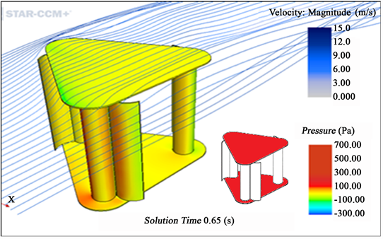
Figure 10. Effect of fully covered protection plates of model Q.

Table 1. Performance table of models A to Q.
for model Q it is recognized that the fully covered protection plates successfully prevent wingtip vortices from interfering with the end of the circular cylinder. Since pressure loss on the wing surface was not induced by wingtip vortices, sufficient lift forces due to Magnus effect can be obtained.
4.2. Effect of Curved Wings
Figure 11 shows the effects of curved wings. Curved wings have two effects. One is effect of drag forces caused by the wing. Compared with the flat plate of models C and D, curved wings efficiently gain drag forces due to curved configuration

Figure 11. Effect of curved wings of model Q.
shown in the figure. The other effect is to enhance Magnus force. Airflows impinging the curved wing cause the increasing positive pressure which leads to greater pressure gap on the cylinder surface. Solution time indicates the time when the most representative situation was obtained. Solution time of the figures is different since it depends on the simulation results.
5. Conclusions
The paper aims to control wingtip vortices to improve power generation capacity. As a result, following findings were obtained.
Numerical study was conducted for 14 models to find out control factors to suppress wingtip vortices. Numerical simulation visualized wingtips by streamlines as well as pressure distribution on the circular cylinder for evaluating Magnus effect. As a result, the following findings were obtained.
1) Installation of fully covered protection plates at both ends of the circular cylinder blades is greatly effective to suppress the wingtip vortices.
2) Curved wings attached to each cylinder are more effective to enhance power generation efficiency than flat ones, due to great increase in Magnus effect caused by large pressure difference on both sides of the curved wing.
The power efficiency of the optimized model was improved up to 2.8%, which means 11 times that of the original model.
Acknowledgements
This work has been supported by Japan Grant-in-Aid for Scientific Research (C) under contract No. 17K06174.
Conflicts of Interest
The authors declare no conflicts of interest regarding the publication of this paper.
Cite this paper
Ogawa, S. and Kimura, Y. (2018) Performance Improvement by Control of Wingtip Vortices for Vertical Axis Type Wind Turbine. Open Journal of Fluid Dynamics, 8, 331-342. https://doi.org/10.4236/ojfd.2018.83021
References
- 1. Azharrudin, A. (2013) Cellular Rotating Cylinder Design as a Lifting Generator. ICMER.
- 2. Mittal, S. and Kumar, B. (2003) Flow past a Rotating Cylinder. Journal of Fluid Mechanics, 476, 303-334. https://doi.org/10.1017/S0022112002002938
- 3. Takahashi, T. (2016) An Innovative Wind/Water Turbine with Circular Cylinder Propeller Driven by Longitudinal Vortex. Proceeding of 1st WWEC Conference, Fkushima, 3-4 November 2016.
- 4. Sakamoto, K., Hemuswan, W., Yoshitake, Y. and Takahashi, T. (2016) Performance Test of a Novel Wind Turbine Propeller with Circular Blades Driven by Longitudinal Vortex. Proceeding of 94th JSME Conference, Yamaguchi University, Japan.
- 5. Sakamoto, K., Hemuswan, W. and Takahashi, T. (2017) Enhancement of Efficiency of a New Horizontal Type Turbine Driven by Longitudinal Vortex. TFEC9-1421.
- 6. Koide, M., Oogane, K., Takahashi, T. and Shirakashi, M. (2004) Experimental Study on University of Longitudinal Vortices Shedding Periodically from Crisscross Circular Cylinder System. Journal of the Visualization Society of Japan, 24, 15-22. https://doi.org/10.3154/tvsj.24.15
- 7. Ogawa, S., Nomura, T. and Hata, N. (2018) Study on Horizontal Type Turbine Driven by Longitudinal Vortex System. The 14th International Conference on Motion and Vibration, MoViC2018, Daejeon Convention Center, Korea, 5-8 August 2018, 249-250.
- 8. Ogawa, S., Kimura, Y. and Sorokin, Y. (2018) Control of Wingtip Vortices by Vertical Type Magnus Wind Turbine. The 14th International Conference on Motion and Vibration, MoViC2018, Daejeon Convention Center , Korea, 5-8 August 2018, Poster Session PS-01.
- 9. Constantinescu, G.S., Pacheco, R. and Squires, K.D. (2002) Detached-Eddy Simulation of Flow over a Sphere. AIAA Aerospace Sciences Meeting 2002, Reno, Paper AIAA 2002-0425.
- 10. Vinokur, M. (1980) On One-Dimensional Stretching Functions for Finite-Difference Calculations. NASA Contractor Report 3313.
- 11. Nakayama, Y. (1999) Introduction to Fluid Mechanics. Butterworth-Heinemann, Oxford, 152.
- 12. Roshko, A. (1961) Experiments on the Flow past a Circular Cylinder at Very High Reynolds Number. Journal of Fluid Mechanics, 10, 345-356. https://doi.org/10.1017/S0022112061000950
- 13. Hadzic, H. (2005) Development and Application of Finite Volume Method for the Computation of Flows around Moving Bodies on Unstructure, Overlapping Grids. Ph.D. Dissertation, Technische Universität Hamburg, Haburg.