American Journal of Analytical Chemistry
Vol. 3 No. 4 (2012) , Article ID: 18433 , 8 pages DOI:10.4236/ajac.2012.34043
Amperometric Glucose Biosensor Based on Integration of Glucose Oxidase with Palladium Nanoparticles/Reduced Graphene Oxide Nanocomposite
School of Chemistry, Northeast Normal University, Changchun, China
Email: *zhuld108@nenu.edu.cn
Received February 13, 2012; revised March 21, 2012; accepted April 1, 2012
Keywords: Reduced Graphene Oxide; Palladium Nanoparticles; Biosensor; Glucose Oxidase
ABSTRACT
We report on a new type of amperometric glucose biosensor that was made by integration of glucose oxidase (GOD) with palladium nanoparticles/reduce graphene oxide (Pd/RGO) nanocomposite. The Pd/RGO was prepared by a onestep reduction method in which the palladium nanoparticles and the reduced graphene oxide (RGO) were simultaneously accomplished from the reduction of dispersed solution of PdCl2 and graphite oxide (GO) with hydrazine. The as-prepared nanocomposite exhibits favorable electrocatalytic activities towards the oxidation of H2O2, which makes it a good platform for the construction of the glucose biosensor. The analytical performance of the glucose biosensor is fully evaluated. It shows good analytical properties in terms of a short response time (3 s), high sensitivity (14.1 µA/mM), and low detection limit (0.034 mM). In addition, the effects of pH value, applied potential, electroactive interference and the stability of the biosensor were discussed as well.
1. Introduction
Though glucose biosensor has been already commercialized for decades, the basic research is still active [1-5]. Especially, amperometric biosensor based on glucose oxidase (GOD) is extremely popular due to its simplicity, reliability, low cost and very stable activity [6-9]. In this type, glucose level is indirectly monitored by measurement of current associated with the electrochemical detection of hydrogen peroxide produced during the enzymatic reaction in which glucose is oxidized by oxygen with the aid of GOD. The side product, hydrogen peroxide, is usually oxidized at conventional solid state electrodes, and unfortunately the kinetics is very sluggish, therefore, high over potentials are often required in order to get a sufficient sensitivities. This may give rise to serious interference from some electroactive species (i.e. ascorbate, urate, acetaminophen, etc.) which are usually present in real samples. To this end, various approaches have been proposed to circumvent or alleviate this issue, for example, coating the enzymes with a preoxidizing layer or a permselective membrane (e.g. Nafion) [10], or incorporation of redox mediators (e.g. porphyrin [11], phthalocyanine [12], Prussian blue [13], and peroxidase [14]) to diminish the over potential for the detection of hydrogen peroxide. Additionally, the oxidation of hydrogen peroxide can be promoted by some precious metal nanoparticles thanks to their large active surface area and favorable lattice planes compare to the bulks, such as Pt and Au [15,16]. Likewise, Pd nanoparticles are also frequently included into sensory configurations for this purpose and practically, they are generally dispersed with a conducting support to avoid their agglomerations and keep their activities. On this aspect, various carbon materials have been employed due to their good electrical conductivities, biocompatibilities and rich in functional groups used for anchoring Pd nanoparticles, for example, carbon nanotubes [17], graphite [18] and mesoporous carbon [19]. In this article, we exploit a new carbon material, reduced graphene oxide (RGO), as the support for Pd nanoparticles for this purpose.
Reduce graphene oxide (RGO), a flat monolayer of graphite packed into a two-dimensional (2D) honeycomb lattice, has become one of the most novel and exciting stars in material science. This inexpensive material has a unique ability to promote fast electron transfer kinetics for a wide range of electroactive species when it is employed as electrode substrate [20-24]. For example, Kang et al. [25] reported that the RGO electrode rich in hydroxyl and carboxylic groups showed promoted electrocatalytic activity towards the oxidation of paracetamol. Kim et al. [26] developed a sensitive sensor for the selective determination of dopamine without the interference of ascorbic acid based on a RGO modified electrode. Shan et al. [27] have used graphene as the electrode material for low-potential NADH detection and biosensing for ethanol. The RGO used in most of the works is generally obtained by the chemical reduction of graphene oxide in solution, and because of the van der Waals and π-π stacking interactions, the RGO sheets are especially easy to form irreversible agglomerates and even restack to form graphite, which may limit their applications. Herein, this issue is gotten over by incorporation of Pd nanoparticles between the RGO sheets and the agglomeration of Pd nanoparticles is circumvented at the same time by supported on RGO in that the Pd nanoparticles and RGO are achieved through a one-step reduction of PdCl2 and graphite oxide (GO) with hydrazine. During the reduction process, Pd nanoparticles are grown on the surface of RGO sheets and prevent their restacking. The obtained nanocomposite exhibits particularly electrocatalytic activities towards the oxidation of hydrogen peroxide. This feature encouraged us to develop a new amperometric glucose biosensor by combination with glucose oxidase.
2. Experimental
2.1. Reagents
Glucose oxidase (GOD, 155.6 U/mg, from Aspergillusniger), palladium(II) chloride (PdCl2), graphite powder, ascorbic acid (AA), uric acid (UA) and acetaminophen (AP) were purchased from Sigma-Aldrich Co. (St. Louis, USA). β-D-Glucose was obtained from Beijing Chemical Reagent Company. Glucose stock solutions were stored at 4˚C and allowed to mutarotate for at least 24 h prior to use. All other chemicals were analytical grade and used as received. Doubly distilled water was used for the preparation of aqueous solutions throughout.
2.2. Preparation of Graphite Oxide
Graphite oxide (GO) was prepared according to a modified Hummer’s method [28]. Briefly, 0.3 g graphite was added into a mixture of 2.4 mL H2SO4 (98%), 0.5 g K2S2O8, and P2O5, and then the mixture was continuously stirred at 80˚C for 4.5 h. The resulted preoxidized product was filtrated and rinsed with copious distilled water, and dried at room temperature overnight. The preoxidized product was added to 12 mL H2SO4 (98%) in an ice-bath. And followed with addition of 1.5 g of KMnO4 gradually while maintaining vigorous agitation. The temperature of the mixture was maintained below 20˚C. The ice-bath was then removed and the temperature of the suspension was leveled up to 35˚C where it was maintained for 2 h. Then 25 mL H2O was added. After 0.5 h, additional 70 mL H2O, which was heated up early, was added to the solution, and 2 mL 30% H2O2 was slowly injected into the solution, then a bright yellow solution was obtained. After that, the mixture was filtrated and washed with water several times to remove the remaining metal ions and acid, then dried at 30˚C under vacuum overnight.
2.3. Synthesis of Pd/RGO Nanocomposite
Pd/RGO was prepared by the following procedures. In brief, 32.0 mg GO, 0.15 mL of 1.13 mM PdCl2, and 170 mL H2O were added into a flask, and vigorously stirred at room temperature for 0.5 h. Then the pH was adjusted to 13 by sodium hydroxide solution. Finally 2 mL 85% hydrazine solution was added into the flask. The solution was refluxed at 90˚C for 3 h, and additionally stirred at room temperature overnight. The resulted solution was filtrated and washed with copious distilled water, and then the filtrate was dried at room temperature overnight. RGO was identically prepared only except for the absence of PdCl2 in the beginning.
The particle sizes and morphologies of the Pd/RGO nanocomposite were characterized by a JEOL 2010 transmission electron microscope (TEM) at 200 kV. The X-ray diffraction (XRD) pattern was obtained with a Philips powder diffraction system (model PW 1830) using a Cu Kα source operating at 40 keV at a scan rate of 0.025∙s–1.
2.4. Preparation of GOD/Pd/RGO/GCE
A glassy carbon electrode (GCE, dia: 3 mm) was polished with 0.05 mm alumina slurry on a piece of polishing cloth and then ultrasonically cleaned in ethanol and distilled water, successively. Pd/RG/GCE was made by casting 5 µL of the Pd/RGO suspension (1 mg/mL, dispersed in DMF with ultrasonic agitation) on the surface of the well-polished GCE. The solvent was allowed to dry under an infrared lamp for 0.5 h. Then the Pd/RGO/GCE was gradually cooled to room temperature. The RGO/ GCE was prepared in the same way.
GOD/Pd/RGO/GCE was prepared according to the following procedures. 0.5 mg GOD and 2.5 mg BSA were dissolved in 50 µL of deoxygenated phosphate buffer solution (0.05 M, pH 6.85), then 10 µL of glutaraldehyde (5%) was added and evenly shaken as soon as possible. After that 3 µL of the mixture was casted onto the surface of the Pd/RGO/GCE. Then the solvent was allowed to dry at room temperature. The GOD/RGO/GCE was prepared in the same way. Both the bioelectrodes were stored in phosphate buffer solution (0.05 M, pH 6.85) at 4˚C in a refrigerator when not in use.
2.5. Apparatus
Electrochemical measurements were performed with a CHI660b electrochemical workstation (Chenhua Instruments Co., Shanghai, China). Three-electrode system with a platinum wire counter and an Ag/AgCl (3 M NaCl) reference electrode was employed in this study. The working electrode was one of the modified GCE described above. The counter, reference and working electrodes were inserted into a 10 mL beaker through holes in its Teflon cover. A magnetic Teflon stirrer provided the convective transport during the amperometric measurements. All the experiments were performed at room temperature (20˚C ± 1˚C).
3. Results and Discussion
3.1. Characterization of the Pd/RGO Nanocomposite
The X-ray diffraction (XRD) patterns of RGO (a) and Pd/RGO (b) are given in Figure 1. The diffraction peak at 23.50˚ and 43.00˚ are indexed to the (002) and (100) planes of RGO, while the diffraction peaks located at 2θ values of 38.59˚, 44.86˚, 66.85˚ and 79.67˚ are attributed to the (111), (200), (220) and (311) planes of Pd, respectively. These peaks indicate that Pd supported on RGO is present in the face-centered cubic (fcc) crystal lattice structure. We estimate the average particle size of the Pd nanoparticles according to the Scherrer equation [29]:
where L is the average particle size, λkαl is the X-ray wave length (0.154056 nm for Cu λkαl radiation), B2θ is the peak broadening, and θB is the angle corresponding to the peak maximum. The value of the volume averaged particle is about 4.09 nm calculated from the full width half maximum of the (220) peak.
Figure 2 shows the transmission electron microscopy (TEM) images of the RGO (A) and Pd/RGO (B). It can be clearly seen that the thickness of flakes is about 3 - 4 nm, which corresponds to about 10 reduced graphene
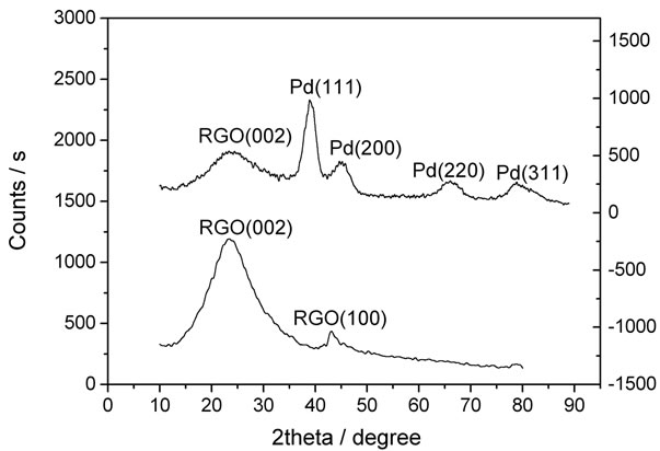
Figure 1. X-ray diffraction patterns of RGO (a) and Pd/ RGO (b).
oxide layers, suggesting the electrochemical behavior of RGO prepared here is similar to that of single layer graphene, as demonstrated by Pumera et al. [30,31]. Yet, they are generally not especially flat, and their edges often exhibit folding or scrolling shapes. From Figure 2 (B), we can discern that Pd nanoparticles are clearly decorated in the RGO nanosheets. The particles display relatively uniform spherical shape with a nominal diameter of 3.5 - 4.5 nm, which is conformed to the datum obtained by the XRD analysis.
3.2. Electrochemical Performance of Pd/RGO/GCE towards Hydrogen Peroxide
Figure 3 depicts the cyclic voltammograms for the oxidation of hydrogen peroxide recorded at Pd/RGO/GCE (A) and RGO/GCE (B) in phosphate buffer solution (0.05 M, pH 6.85) at a scan rate of 50 mV/s. As can be seen, the Pd/RGO/GCE shows much more favorable electrochemical activities towards the catalysis of H2O2 than does the RGO/GCE in terms of the onset potential and current response, suggesting the promotion of Pd nanoparticles towards the catalytic oxidation of H2O2.
Because of the significant electrocatalytic properties of Pd/RGO/GCE, the sensitive detection of hydrogen peroxide is reliable by amperometric method under low over potentials. Then the effect of applied potential on the
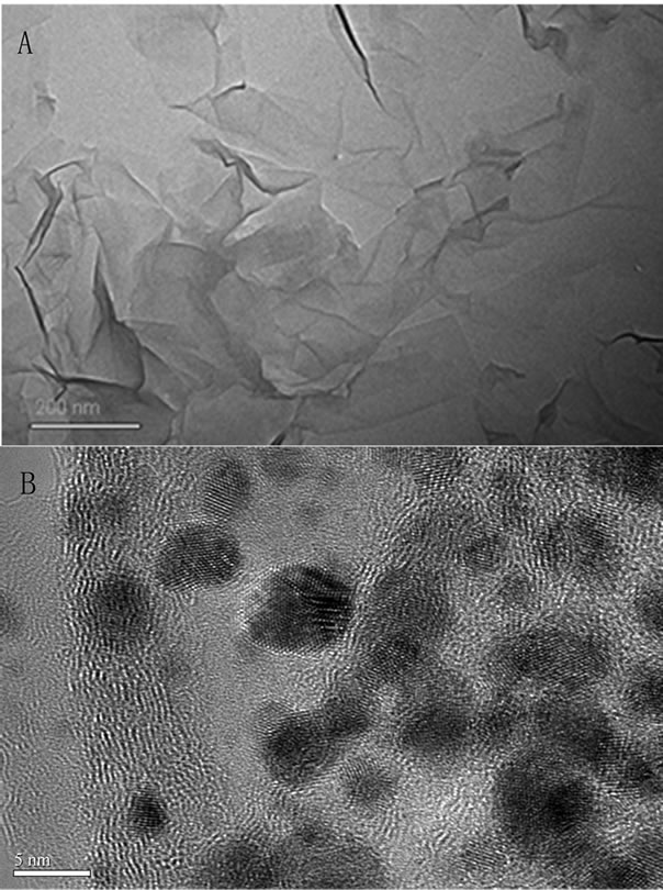
Figure 2. TEM image of RGO (A) and Pd/RGO (B).
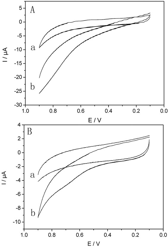
Figure 3. Cyclic voltammograms for Pd/RGO/GCE (A) and RGO/GCE (B) in the absence (a) and the presence (b) of 5 mM H2O2. Scan rate: 50 mV/s, supporting electrolyte: phosphate buffer (0.05 M, pH 6.85).
current response of the Pd/RGO/GCE (A) and RGO/GCE (B) to 1 mM H2O2 had been investigated in detail. The effect of applied potential on the response current was shown in Figure 4. In the case of Pd/RGO/GCE, the current response increases rapidly when the applied potential changes from 0.3 to 0.5 V but levels off when higher than 0.5 V, while the current response is gradually increased for RGO/GCE. Therefore, the operation potential of 0.5 V was selected for oxidation of H2O2 in the following experiments.
Figure 5 displays the typical amperometric responses (A) and the corresponding calibration plots (B) recorded at the RGO/GCE (a) and Pd/RGO/GCE (b) by increasing levels of 0.5 mM steps under the operation potential of 0.5 V. Apparently, As directly perceived through current staircases, the response of RGO/GCE was almost negligible while the response of Pd/RGO/GCE was dramatically increased after each addition of H2O2 indicating the effective detection of H2O2 catalyzed by Pd nanoparticles. To elaborate this point more in detail, we get the analytical data by resolving the calibration curves. The sensitivities are 3.78 and 0.14 µA/mM for the Pd/RGO/GCE and RGO/GCE, respectively. Correspondingly, the detection limit is lowered from 2.31 µM at the RGO/GCE to 1.00 µM at the Pd/RGO/GCE. The linear ranges are up to around 4.00 and 3.00 mM for the Pd/RGO/GCE and RGO/GCE, respectively.

Figure 4. Applied potential on the response of the Pd/ RGO/GCE (a) and RGO/GCE (b) in the presence of 1 mM H2O2.

Figure 5. (A) Current-time responses for successive addition of 0.5 mM H2O2 and (B) corresponding calibration curves for RGO/GCE (a) and Pd/RGO/GCE (b) under the operation potential of 0.5 V.
3.3. Ampermetric Glucose Biosensor
Due to the outstanding electrocatalytic activities of the Pd/RGO/GCE towards H2O2, an ampero-metric glucose biosensor was constructed by integration of glucose oxidase (GOD) with the Pd/ORG/GCE, and the evaluation of glucose concentration in aqueous solution by the biosensor was achieved by the catalytic oxidation of hydrogen peroxide. Figure 6 shows the cyclic voltammograms for the GOD/Pd/RGO/GCE (A) and GOD/RG/GCE (B) recorded in phosphate buffer solution (0.05 M, pH 6.85) in the absence (a) and presence (b) of 5 mM glucose. Upon the addition of glucose, the GOD/Pd/RGO/GCE exhibits typical catalytic cyclic voltammograms associated with increased anodic current. While in the case of the GOD/RGO/GCE, the current responses are almost unchanged before and after the addition of glucose.
Before the amperometric measurement of glucose, we optimized the experimental variables, such as the pH value of the testing media and the applied potential on the bioelectrode, which would ultimately affect the performance of the biosensor. Figure 7(A) shows the effect
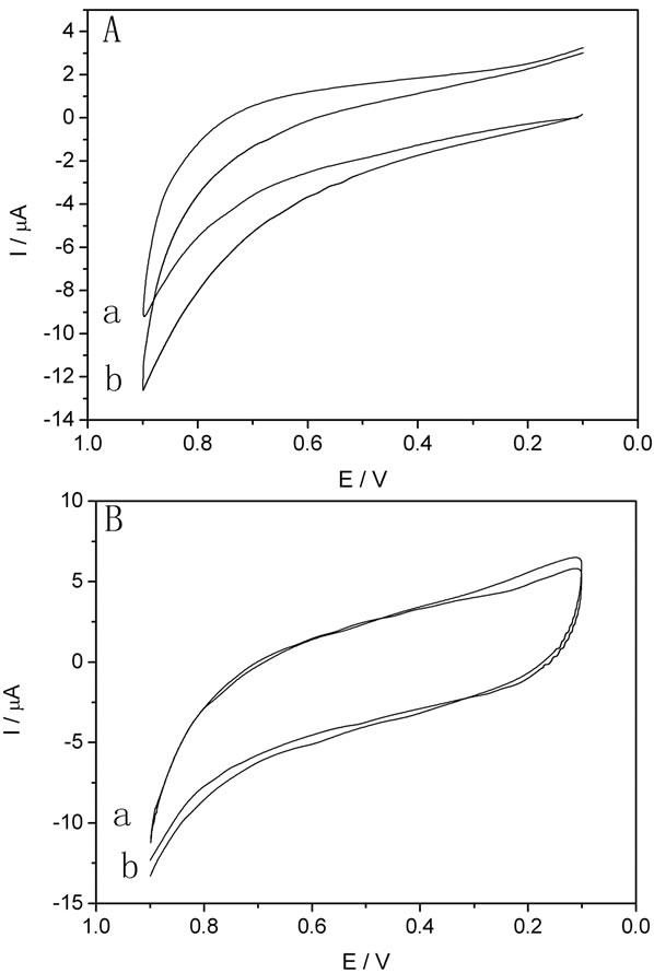
Figure 6. Cyclic voltammograms for GOD/Pd/RGO/GCE (A) and GOD/RGO/GCE (B) recorded in phosphate buffer (0.05 M, pH 6.85) in the absence (a) and the presence (b) of 5 mM glucose at a scan rate of 50 mV/s.
of pH on the response of the biosensor, and the maximum current respond is achieved at around pH 6.85, which is similar to a previous report [32]. Figure 7(B) shows the effect of the applied potential on the response of the biosensor in the presence of 0.05 mM glucose. The current response increases rapidly as the applied potential shifted from 0.3 V to 0.5 V and then levels off afterward. Therefore, the testing media of pH 6.85 and applied potential of 0.5 V are preferred in the following experiments.
Figure 8(A)" target="_self">Figure 8(A) depicts the current-time curves for the GOD/Pd/RGO/GCE (a) and COD/RGO/GCE (b) upon the successive addition of different concentrations of glucose in a stirred buffer solution under the optimal experiment conditions. Both the glucose biosensors have rapid responses to the each addition of glucose, less than 3 s (reaching 95% of stabilized current signal), which are less than previous reports [33,34]. But the amperometric response of the GOD/Pd/RGO/GCE is much higher than that of the GOD/RGO/GCE with respect to the same amount of glucose. Then we only conclude the analytical
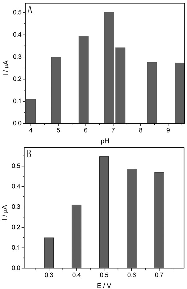
Figure 7. Effect of pH (A) and applied (B) on the response of the biosensor (GOD/Pd/RGO/GCE) in the presence of 0.01 mM glucose.
data for the GOD/Pd/RGO/GCE biosensor from the calibration curves shown in Figure 8(B), while the data of the GOD/RGO/GCE biosensor is obviously very poor. A sensitivity of 14.1 µA/mM, which is higher than those reported based Pd nanoparticles [35,36], a estimated detection limit (based on the signal to noise ratio of 3) of 0.0337 mM, which is much lower than the previous reports [37,38], and a broad dynamic range up to 0.1mM, were obtained for the GOD/Pd/RGO/GCE. The apparent Michaelis-Menten constant ( ) was calculated to be 0.0571 mM for the GOD/Pd/RGO/GCE, according to the lineweaver-burk equation [39].
The operational and long-term stability (shelf lifetime) of the glucose biosensor was studied. The GOD/Pd/ RGO/GCE was incorporated in the electrochemical cell with stirred 0.01 mM glucose solution to study its operational stability under continuous use for 5 h, the current response decreases by only about 10.0% within the 5 h, which indicates the biosensor has a good operational stability and enough for continuous usage for hours. The storage stability of the biosensor was investigated by performing triplicate measurements of 0.01 mM glucose solution in phosphate buffer solution (0.05 M, pH 6.85)
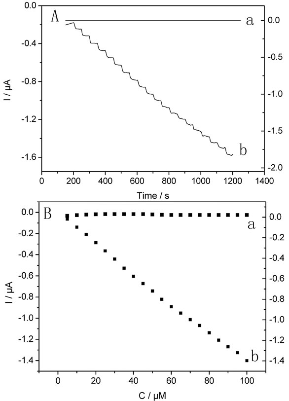
Figure 8. Current-time curves for successive addition of 0.005 mM glucose in a stirring phosphate buffer (0.05 M, pH 6.85) (A) and the corresponding calibration curves (B) for GOD/RGO/GCE (a) and GOD/Pd/RGO/GCE (b) recorded at 0.5 V.
daily. When not in use, the biosensor was kept in phosphate buffer solution (0.05 M, pH 6.85) at 4˚C. The bio sensor retained approximately 85% of the initial sensitivity after 4 days of continual measurments. With the storage time prolonged, the response continues dropping but still retains approximately 60.0% of its initial sensitivity after two weeks of continual measurements.
The interferences from electroactive compounds commonly present in physiological samples of glucose such as uric acid (UA), ascorbic acid (AA) and acetami nophen (AP) used to cause problems in the accurate determination of glucose. The effects of those possible interfering substances upon the response of the glucose biosenseor were evaluated at the operation potential of 0.5 V. It was easily discovered that addition of 0.004 mM UA to 0.01 mM glucose solution did not cause any impact on the response of the biosensor, whereas 0.002 mM AA and 0.002 mM AP brought significant interference on the response of the biosensor in the presence of 0.01 mM glucose. To this end, several approaches have been proposed to overcome this problem, for instance, coating the enzymes with a preoxidizing layer or a permselective membrane (e.g. Nafion) [12], or selective catalysts (e.g. porphyrin [13], phthalocyanine [14], and metallic particles [17,18]) to diminish the over potential for the anodic oxidation of hydrogen peroxide.
4. Conclusion
This article demonstrates that palladium nanoparticles/ graphene nanocomposite has excellent catalytic activities towards the oxidation of H2O2. After immobilizing the glucose oxidase on the nanocomposite Pd/RGO/GCE, a new amperometric glucose biosensor has been successfully developed. The glucose biosensor shows good analytical characteristics such as a short response time (3 s), high sensitivity (14.1 µA/mM), low detection limit (0.0337 mM) and good stability under the optimized experimental conditions. What more, the novel biosensor are not interfered by UA due to the lower operation potential afforded by the catalytic ability of the presence of Pd nanoparticles. All those facts suggest that the GOD/Pd/ RGO/GCE holds great promise in electrobiosensor.
5. Acknowledgements
The authors are profoundly grateful for the financial support from the Training Fund of NENU’S Scientific Innovation Project (No. NENU-STC08011) and the Science Foundation of Jilin Province (20090532).
REFERENCES
- C. Shan, H. Yang, D. Han, Q. Zhang, A. Ivaska and L. Niu, “Graphene/AuNPs/Chitosan Nanocomposites Film for Glucose Biosensing,” Biosensors and Bioelectronics, Vol. 25, No. 5, 2010, pp. 1070-1074. doi:10.1016/j.bios.2009.09.024
- Y. Lin, F. Lu, Y. Tu and Z. Ren, “Glucose Biosensors Based on Carbon Nanotube Nanoelectrode Ensembles,” Nano Letters, Vol. 4, No. 2, 2004, pp. 191-195. doi:10.1021/nl0347233
- H. Wu, W. Cao, G. Liu, Y. Wen, H. Yang and S. Yang, “In Situ Growth of Copper Nanoparticles on Multiwalled Carbon Nanotubes and Their Application as Non-Enzymatic Glucose Sensor Materials,” Electrochimica Acta, Vol. 55, No. 11, 2010, pp. 3734-3740. doi:10.1016/j.electacta.2010.02.017
- Y. Liu, D. Zeng, Z. Miao and L. Dai, “Biocompatible Graphene Oxide-Based Glucose Biosensors,” Langmuir, Vol. 26, No. 9, 2010, pp. 6158-6160. doi:10.1021/la100886x
- J. Wang and M. Musameh, “Carbon Nanotubes Doped Polypyrrole Glucose Biosensor,” Analytica Chimica Acta, Vol. 539, No. 1-2, 2005, pp. 209-213. doi:10.1016/j.aca.2005.02.059
- L. Zhu, R. Yang, J. Zhai and C. Tian, “Bioenzymatic Glucose Biosensor Bansed on Co-Immobilization of Peroxidase and Glucose Oxidase on a Carbon Nanotubes Electrode,” Biosensors and Bioelectronics, Vol. 23, No. 4, 2007, pp. 528-535. doi:10.1016/j.bios.2007.07.002
- K. Zhou, Y. Zhu, X. Yang and C. Li, “Electrcatalytic Oxidation of Glucose by the Glucose Oxidase Immobilized in Graphene-Au-Nafion Biocomposite,” Electroanalysis, Vol. 22, No. 3, 2010, pp. 259-264. doi:10.1002/elan.200900321
- C. Shan, H. Yang, J. Song, D. Han, A. Invaska and L. Niu, “Direct Electrochemistry of Glucose Oxidase and Biosensing for Glucose Based on Graphene,” Analytical Chemistry, Vol. 81, No. 6, 2009, pp. 2378-2382. doi:10.1021/ac802193c
- H. Tang, J. Chen, S. Yao, L. Nie, G. Deng and Y. Kuang, “Amperometric Glucose Biosensor Based on Adsorption of Glucose Oxidase at Platinum Nanoparticle-Modified Carbon Nanotube Electrode,” Analytical Biochemistry, Vol. 331, No. 1, 2004, pp. 89-97.
- G. G. Wallace, M. Smyth and H. Zhao, “Conducting Electroactive Polymer-Based Biosensors,” Trends in Analytical Chemistry, Vol. 18, No. 4, 1999, pp. 245-251. doi:10.1016/S0165-9936(98)00113-7
- K. I. Ozoemena and T. Nyokong, “Novel Amperometric Glucose Biosensor Based on an Ether-Linked Cobalt(II) Phthalocyanine-Cobalt(II) Tetraphenylporohyrin Pentamet as a Redox Mediator,” Electrochimica Acta, Vol. 51, No. 24, 2006, pp. 5131-5136. doi:10.1016/j.electacta.2006.03.055
- J. Ye, Y. Wen, W. Zhang, H. Cui, G. Xu and F. S. Sheu, “Electrochemical Biosensing Platforms Using Phthalocyanine-Functionalized Carbon Nanotube Electrode,” Electroanalysis, Vol. 17, No. 1, 2005, pp. 89-96. doi:10.1002/elan.200403124
- L. Zhu, J. Zhai, Y. Guo, C. Tian and R. Yang, “Amperometric Glucose Biosensors Based on Integration of Glucose Oxidase onto Prussian Blue/Carbon Nanotubes Nanocomposite Electrodes,” Electroanalysis, Vol. 18, No. 18, 2006, pp. 1842-1846. doi:10.1002/elan.200603594
- L. Zhu, R. Yang, J. Zhai and C. Tian, “Bienzymatic Glucose Biosensor Based on Co-Immobilization of Peroxidase and Glucose Oxidase on a Carbon Nanotubes343 Electrode,” Biosensors and Bioelectronics, Vol. 23, No. 4, 2007, pp. 528-535. doi:10.1016/j.bios.2007.07.002
- S. Hrapovic, Y. Liu, K. B. Male and J. H. T. Luong, “Electrochemical Biosensing Platforms Using Platinum Nanoparticles and Carbon Nanotubes,” Analytical Chemistry, Vol. 76, No. 4, 2004, pp. 1083-1088. doi:10.1021/ac035143t
- N. German, A. Ramanaviciene, J. Voronovic and A. Ramanavicius, “Glucose Biosensor Based on Graphite Modified with Oxidase and Colloidal Gold Nanoparticles,” Microchimica Acta, Vol. 168, No. 3-4, 2010, pp. 221- 229. doi:10.1007/s00604-009-0270-z
- J. C. Claussen, A. D. Franklin, A. Haque, D. M. Porterfield and T. S. Fisher, “Electrochemical Biosensor of Nanocube-Augmented Carbon Nanotube Networks,” ACS Nano, Vol. 3, No. 1, 2009, pp. 37-44. doi:10.1021/nn800682m
- S. A. Miscoria, G. D. Barrera and G. A. Rivas, “Analytical Performance of Glucose Biosensor Prepared by Immobilization of Glucose Oxidase and Different Metals into a Carbon Paste Electrode,” Electroanalysis, Vol. 14, No. 14, 2002, pp. 981-987. doi:10.1002/1521-4109(200208)14:14<981::AID-ELAN981>3.0.CO;2-1
- X. Jiang, Y. Wu, X. Mao, X. Cui and L. Zhu, “Amperometric Glucose Biosensor Based on Integration of Glucose Oxidase with Platinum Nanoparticles/Ordered Mesoporous Carbon Nanocomposite,” Sensors and Actuators B: Chemical, Vol. 153, No. 1, 2011, pp. 158-163. doi:10.1016/j.snb.2010.10.023
- Y. Wang, Y. Li, L. Tang, J. Lu and J. Li, “Application of Graphene-Modified for Selective Detection of Dopamine,” Electrochemistry Communications, Vol. 11, No. 4, 2009, pp. 889-892. doi:10.1016/j.elecom.2009.02.013
- Z. Liu, Y. Xu, X. Zhang, X. Zhang, Y. Chen and J. Tian, “Prophyrin and Fullerene Cocalently Functionalized Graphene Hybrid Materials with Large Nonlinear Optical Properties,” Journal of Physical Chemistry B, Vol. 113, No. 29, 2009, pp. 9681-9686. doi:10.1021/jp9004357
- M. Zhou, Y. Wang, Y. Zhai, J. Zhai, W. Ren, F. Wang and S. Dong, “Controlled Synthesis of large-Area and Parrerned Electrochemically Reduced Graphene Oxide Films,” Journal of European Chemistry, Vol. 15, No. 25, 2009, pp. 6116-6120. doi:10.1002/chem.200900596
- S. Wang. P. K. Ang, Z. Wang, A. L. L. Tang, J. T. L. Thong and K. P. Loh, “High Mobility, Printable, and Solution-Processed Graphene Electronics,” Nano Letters, Vol. 10, No. 1, 2010, pp. 92-98. doi:10.1021/nl9028736
- G. Eda, G. Fanchini and M. N. Chhowalla, “Large-Area Ultrathin Films of Reduced Graphene Oxide as a Transparent and Flexible Electronic Material,” Nanotechnology, Vol. 3, No. 5, 2008, pp. 270-274.
- X. Kang, J. Wang, H. Wu, J. Liu, I. A. Aksay and Y. Lin, “A Graphene-Based Electrochemical Sensor for Sensitive Detection of Paracetamol,” Talanta, Vol. 81, No. 3, 2010, pp. 754-759. doi:10.1016/j.talanta.2010.01.009
- Y. R. Kim, S. Bong, Y. J. Kang, Y. Yang, R. K. Mahajan, J. S. Kim and H. Kim, “Electrochemical Detection of Dopamine in the Presence of Ascorbic Acid Using Graphene Modified Electrodes,” Biosensors and Bioelectronics, Vol. 25, No. 10, 2010, pp. 2366-2369. doi:10.1016/j.bios.2010.02.031
- C. Shan, H. Yang, D. Han, Q. Zhang, A. Ivaska and L. Niu, “Electrochemical Determination of NADH and Ethanol Based on Ionic Liquid-Functionalized Graphene,” Biosensors and Bioelectronics, Vol. 25, No. 6, 2010, pp. 1504- 1508. doi:10.1016/j.bios.2009.11.009
- C. N. R. Rao, A. K. Subrahmanyam and A. Govindaraj, “Graphene: The New Two-Dimensional Nanomaterial,” Angewandte Chemie, Vol. 48, No. 42, 2009, pp. 7752-7777. doi:10.1002/anie.200901678
- Z. Liu, J. Y. Lee, W. Chen, M. Han and L. Gan, “Physical and Electrochemical Characterizations of MicrowaveAssisted Polyol Preparation of Carbon-Supported Pt Ru Nanoparticles,” Langmuir, Vol. 20, No. 1, 2004, pp. 181- 187. doi:10.1021/la035204i
- M. S. Goh and M. Pumera, “The Electrochemical Response of Graphene Sheets Is Independent of the Number of Layers from a Single Graphene Sheets to Multilayer Stacked Graphene Platelets,” Chemistry—An Asian Journal, Vol. 5, No. 11, 2010, pp. 2355-2357. doi:10.1002/asia.201000437
- M. S. Goh and M. Pumera, “Single-, Few-, and Multilayer Graphene Not Exhibiting Significant Advantages over Graphite Micoropartcles in Electroanalysis,” Analytical Chemistry, Vol. 82, No. 19, 2010, pp. 8367-8370. doi:10.1021/ac101996m
- P. Santhosh, K. M. Manesh, S. Uthayakumar, S. Uthayakumar, S. Komathi, A. I. Gopalan and K. P. Lee, “Fabrication of Enzymatic Glucose Biosensor Based on Palladium Nanoparticles Dispersed onto Poly (3,4-Ethylenedioxythiophene) Nanofibers,” Bioelectrochemistry, Vol. 75, No. 1, 2009, pp. 61-66. doi:10.1016/j.bioelechem.2008.12.001
- M. Zhou, Y. Wang, Y. Zhai, J. Zhai, W. Ren, F. Wang and S. Dong, “Controlled Synthesis of Large-Area and Parrerned Electrochemically Reduced Graphene Oxide Films,” Journal of European Chemistry, Vol. 15, No. 25, 2009, pp. 6116-6120. doi:10.1002/chem.200900596
- Z. Liu, Y. Xu, X. Zhang, X. Zhang, Y. Chen and J. Tian, “Prophyrin and Fullerene Cocalently Functionalized Graphene Hybrid Materials with Large Nonlinear Optical Properties,” Journal of Physical Chemistry B, Vol. 113, No. 29, 2009, pp. 9681-9686. doi:10.1021/jp9004357
- W. J. Ho, C. J. Yuan and O. Reiko, “Application of SiO2- Poly (Dimethylsiloxane) Hybrid Material in the Fabrication of Ampermnetric Biosensor,” Analyca Chimica Acta, Vol. 572, No. 2, 2009, pp. 248-252. doi:10.1016/j.aca.2006.05.022
- J. C. Claussen, A. D. Franklin, A. U. Haque, D. M. Porterfield and T. Fisher, “Electrochemical Biosensor of Nanocube-Augmented Carbon Nanotube Networks,” ACS Nano, Vol. 3, No. 1, 2009, pp. 37-44.
- F. Xiao, F. Zhao, D. Mei, Z. Mo and B. Zeng, “Nonenzymatic Glucose Sensor Based on Ultrasonic-Electrodeposition of Bimetallic PtM (M = Ru, Pd, and Au) Nanoparticles on Carbon Nanotubes-Ionic Liquid Composite Film,” Biosensors and Bioelectronics, Vol. 24, No. 12, 2009, pp. 3481-3486. doi:10.1016/j.bios.2009.04.045
- S. H. Lim, J. Wei, J. Lin, Q. Li and J. KuaYou, “A Glucose Biosensor Based on Electrodeposition of Palladium Nanoparticles and Glucose Oxidase onto Nafion-Solubilized Carbon Nanotube Electrode,” Biosensors and Bioelectronics, Vol. 20, No. 12, 2005, pp. 2341-2346. doi:10.1016/j.bios.2004.08.005
- R. A. Kamin and G. S. Wilson, “Rotating Ring-Disk Enzyme Electrode for Biocatalysis Kinetic Studies and Characterization of the immobilized Enzyme Layer,” Analytical Chemistry, Vol. 52, No. 8, 1980, pp. 1198-1205. doi:10.1021/ac50058a010
NOTES
*Corresponding author.