Modeling and Numerical Simulation of Material Science
Vol.3 No.3A(2013), Article ID:35594,4 pages DOI:10.4236/mnsms.2013.33A006
Micro-Modelling Approach to Predict the Influence of Hydrogen Pressure on Short Crack Behaviour
1UTC Pratt & Whitney Canada, Longueuil, Canada
2Hydro-Quebec Research Institute, Varennes, Canada
3Department of Mining, Metallurgical and Materials Engineering, Laval University, Quebec, Canada
Email: claude.lincourt@pwc.ca, lanteigne.jacques@ireq.ca, devk@rogers.com
Copyright © 2013 Claude Lincourt et al. This is an open access article distributed under the Creative Commons Attribution License, which permits unrestricted use, distribution, and reproduction in any medium, provided the original work is properly cited.
Received June 5, 2013; revised July 5, 2013; accepted July 12, 2013
Keywords: Hydrogen; Toughness; Finite Element Analysis; Modelling; Characteristic Length; Fracture Stress
ABSTRACT
A micromechanical model, based on the FEA (finite element analysis), was developed to estimate the influence of hydrogen pressure on short crack behaviour. Morphology of voids has important connotations in the development of the model. Stress intensity factor was calculated for different crack geometries under hydrogen pressure. The analysis indicates that the form factor of a crack emerging from a round void will be less affected by trapped hydrogen pressurecompared to an elongated void. This analysis reinforces the beneficial effect of inclusion shape control in reducing significantly the detrimental effect of hydrogen.
1. Introduction
Stress intensity factor at the onset of crack initiation depends on the local stress distribution in the vicinity of a microstructural stress raiser. Crack growth then occurs in a limited region, whose extent depends on the local stress variation resulting from material heterogeneities. The knowledge of the stress condition for a microcrack emerging from a heterogeneity is then of prime importance to determine its sensitivity to microstructure. Lincourt, et al. [1,2] proposed that the stress intensity factor of a small microcrack emerging from voids is higher than the values reported in literature. In this study, we will use a similar FEA model to analyse the stress intensity factor of a microcrack when local hydrogen pressure in voids is superposed on the remote stress.
2. Mechanical Effect of Hydrogen in Voids/Inclusions on Fracture Toughness of Steel
2.1. Introduction
The effect of hydrogen on the properties and the fracture mode of steel has been an object of study since more than a century. Thousand of articles have been written about this topic and several papers give a very good chronological resume of the studies carried out on the subject as those of Moody and Robinson [3] and Bernstein [4]. An important part of the research has concentrated on the cohesion effect of hydrogen on steel notch toughness reduction. Although the effect of local hydrogen pressure alone on steel toughness is considered by Knott [5] to be of less significance, Interante and Pressouyre [6] demonstrated through development of hydrogen induced cracking model (HIC), and more recently, Bergmann, et al. [7] showed, by using finite element analysis techniques, that the local pressure effect on steel toughness is strongly dependant of the hydrogen trap site geometry.
2.2. Hydrogen Pressure in Voids/Inclusions
The work of Pyun and Kim [8] indicates that the defects like micro voids and water quenched dislocations located at the interface between manganese sulphide inclusions and steel act as deep trap sites for hydrogen. It also suggests that hydrogen charging in mild steel is not influenced by the shape of the inclusion but by the number of sites available per unit volume. A steel richer in manganese sulphide inclusions will be more resistant to HIC than the one that has less available sites. Interrante and Pressouyre [6] demonstrate that HIC immune steel can be produced if the sulphur level is maintained below 0.002% and the phosphorus content is low. This is explained by the fact that low sulphur steels give rounder, finer and homogeneously distributed manganese sulphide inclusions that act as hydrogen trap sites throughout the matrix. On the other hand, the work of Warren [9] indicates that a steel that has a maximum of 0.010% of sulphur and have rounded inclusion obtained by calcium shape control offer optimum resistance to blistering.
2.3. The Use of Finite Element Analysis to Predict the Effect of Hydrogen Pressure in Voids/Inclusions on Steel Transverse Toughness
The work of Bergmann, et al. [10] is probably one of the most important studies using finite element analysis to determine the relationship between the critical hydrogen trap site pressure and the KIC. The equilibrium hydrogen pressure in the trap site is determined in relation to the hydrogen activity at the surface. The relationship between the hydrogen pressure and the stress generated at the inclusion trap site is a function of the inclusion shape factor. The study shows that the shape of the trap site has a significant effect on the critical pressure to attain the steel KIC. The smaller and the rounder are the trap sites, the higher will be the critical pressure to reach KIC. This result is in accordance with that of Interrante and Pressouyre [6].
2.4. The Importance of Inclusion Shape Control
The importance of inclusion shape factor has been well demonstrated from literature. The two main advantages of inclusion shape control are to increase the transverse toughness properties of steel by reducing anisotropy between the longitudinal and transversal orientation and to increase the resistance of steel to HIC. In this study, we use sub-microstructure finite element meshing to analyse the influence of the inclusion shape and local hydrogen pressure on the stress intensity factor of microscopic crack.
3. Calculating the Stress Intensity Factor Using FEA
The Finite Element Analysis (FEA) model presented here is similar to the approach developed previously in this research program [1,2]. The FEA model is a two dimension finite element mesh idealization of a 40 mm by 80 mm steel bar with high mesh refinement. The smallest element size was set at 0.023 µm to get a convergent solution. The FEA model simulates two extreme voids morphologies namely the round and the elongated shape. For the round void, the radius was fitted for 1 mm. For the elongated void, two round voids were combined with their centre set 22 µm apart, thus creating a 24 µm void. This later void shape resembles to the elongated manganese sulphide (MnS) stringers that are commonly observed in steels.
The stress intensity form factor, defined as:
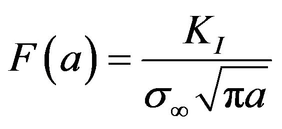 (1)
(1)
with KI the SIF in mode I, s¥, the remote stress and a, the crack length. F(a) was estimated from FEA results and was fitted for1mm of crack propagation, which is considered here to be the extent of the stress concentration near-field for a void charged with hydrogen. The following empirical relation is proposed [1]:
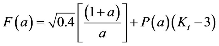 (2)
(2)
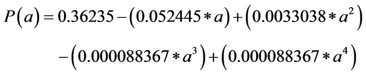
with Kt the stress concentration factor and P(a) is obtained from the relationship:
4. Introduction of Hydrogen Pressure in Voids Having Microcracks
The method used to introduce hydrogen pressure in a FEA model is done by distributing forces on nodes inside a cavity, proportionately to the length of the element edge between two nodes. Hydrogen pressure is then simulated by initial conditions surface loads acting in the outward normal direction along the boundary of the void. The particularity of this study is to simulate at the same time hydrogen pressure inside a void and inside the lips of a microcrack emerging from this void. The same forces are then applied to each detached node along the length of the simulated microcrack. The stress generated by the local hydrogen pressure is then added to the remote stress. This way, each surrounding element is then subjected to a simulated local hydrogen pressure acting on the stress intensity factor and on the emerging microcrack.
5. Voids with Micro Crack up to 1 (m
The first hypothesis, brought in this study about hydrogen, is that a void could still have trapped hydrogen at a high pressure even though there is a microcrack emerging from this void. To be realistic and in accordance with previous work, we fixed the maximum micro crack length to be 1 µm. This allows the model to calculate five crack increments up to 1 µm, emerging from a round and elongated void under hydrogen pressure of 625 and 1250 MPa. We choose these pressures because the typical elastic limit for spring steel is around 1250 MPa, 625 MPa being an intermediate case for model development. The second hypothesis is that a static crack emerging from a void under hydrogen pressure must be also under the same pressure. Then, on each node being detached to create the crack, we applied the same proportional outward force as for the adjacent void to simulate hydrogen pressure at the crack mouth.
6. Results and Discussion
6.1. Simulation of the Local Mechanical Effect of Internal Hydrogen
The model simulates a round and an elongated void under internal hydrogen pressure of 625 and 1250 MPa with a remote loading of 50 MPa. The hydrogen load is equally applied on each of the void and microcrack nodes in order to calculate the K factor for each microcrackstep. These results regrouping simulation with and without hydrogen pressure are presented in Figure 1.The result shows that there is a significant difference between the behaviour of the round and the elongated void charged with hydrogen. The difference in the F factors is about twice for the elongated void compared with the round one at a given pressure and crack length. This difference is indeed due to the difference in the stress concentration between the round and elongated void, except for the first crack step where we should give a particular attention. It was observed that for an emerging crack, the stress concentration factor of a stress raiser appears to play a minor role on the F factor value of this crack at the first propagation step [1]. The notch radius was proposed to be the driving factor as this radius is and because this radius is similar for the round and the elongated voids.
Now, the situation is quite different because the hydrogen loading is applied locally to the void and added to the remote loading. The pressure, being applied inside the void, the stress concentration will affect more the local K value of the emerging crack. As it could be seen in Figure 1, the percentage difference increase in the F factor is almost entirely controlled by internal hydrogen pressure while the void radius effect seen previously is almost hidden. The most important feature that could be observed in this figure is the influence of the void shape factor on the resulting F factor at given hydrogen internal pressure.
The Table 1 presents the difference between the F factor with and without hydrogen pressure for round and elongated voids.
For a given void shape, the hydrogen internal pressure has a linear effect on the F factor. When the pressure is doubled, the difference in the F factor at a given crack length is doubled. The FEA calculation indicates that the F factor of a crack emerging from a round trap site will be slightly affected by trapped hydrogen in comparison
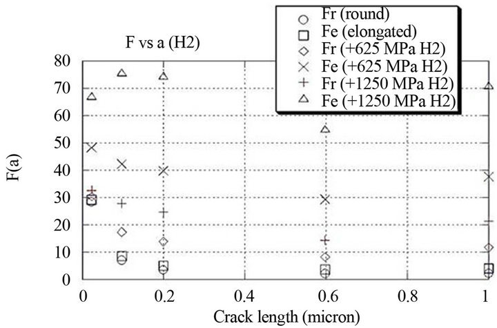
Figure 1. Form factor versus crack length for round and elongated.
with an elongated trap site. This analysis enforces the beneficial effect of inclusion shape control on steel toughness.
6.2. Development of an Equation to Estimate the Effect of Hydrogen Pressure for Very Small Crack (a ≤ 0.2 µm)
To Equation (2) we will have to add a second variable to describe the effect of the hydrogen internal pressure on the geometrical correction factor. We concentrated our interest into the very first steps of propagation to have a relationship between the pressure and the stress concentration factor Kt in terms of the difference in the F factor as follows:
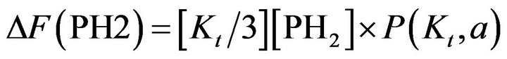 (3)
(3)
where P(Kt, a) is a polynomial defined by:
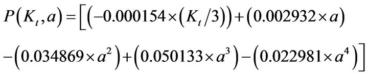 (4)
(4)
where 0.2 ≥ a ≥ 0 µm
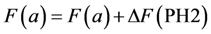 (5)
(5)
Figure 2 presents the results for the first 3 steps of propagation. This figure indicates that the model proposed gives an approximation of F values obtained with FEA in presence of a hydrogen internal pressure.
7. Summary and Conclusion
The objective of this study was to estimate the mechaniccal influence of trapped hydrogen on short crack behaveiour. A FEA model was developed to simulate different levels of internal hydrogen pressure in voids of different shapes. The particularity of this analysis is to simulate at the same time, hydrogen pressure inside a void and in-
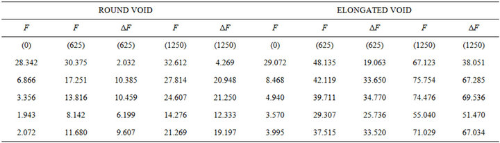
Table 1. Difference between the geometrical correction factor F values with and without hydrogen internal pressure for round and elongated voids.
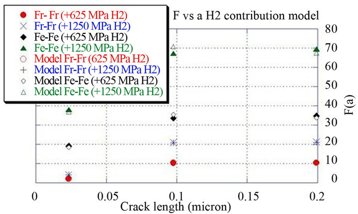
Figure 2. Difference between geometrical correction factor F calculated with FEA versus our model due to hydrogen internal pressure.
side the lips of a crack emerging from this void. The model proposed gives a good approximation of the F(a) values obtained with FEA analysis in the presence of hydrogen internal pressure.
The analysis indicates that the form factor of a crack emerging from a round void will be less affected by trapped hydrogen pressure in comparison with an elongated void. This analysis reinforces the beneficial effect of inclusion shape control in reducing significantly the detrimental effect of hydrogen.
8. Acknowledgements
The authors are grateful to NSERC (Natural Sciences and Engineering Research Council of Canada) for the financial support provided. They also express their sincere thanks to Pratt and Whitney Canada, IREQ (Research Institute of Quebec Hydro). They are also grateful to Maude Larouche, Laval University.
REFERENCES
- C. Lincourt, “Modelling and Optimization of Fracture Toughness of High Strength Steels Using Finite Element Analysis: the Role of Inclusion Morphology and Hydrogen Pressure,” PhD Thesis, Laval University, Quebec, Canada, 2002.
- C. Lincourt, J. Lanteigne and M. Krishnadev, “Effect of Inclusion Morphology on Fracture Toughness of High Strength Steels,” MS&T’09, Pittsburgh, 2009.
- N. R. Moody, S. L. Robinson, “Hydrogen Effect on the Properties and Fracture Modes of Iron-Based Alloys,” Res Mechanica, Vol. 30, 1990, pp. 143-206.
- I. M. Bernstein, “The Role of Hydrogen: Is the Story Any Clearer,” The Minerals, Metals & Materials Society, Warrendale, 1996, pp. 3-11.
- J. F. Knott, “Fracture Toughness and Hydrogen-Assisted Crack Growth in Engineering Alloys,” The Minerals, Metals & Materials Society, Warrendale, 1996, pp. 387-408.
- C. G. Interrante, G. M. Pressouyre, “Current Solution to Hydrogen Problems in Steels,” First International Conference on Current Solution to Hydrogen Problems in Steels, Washington DC, 1-5 November 1982, pp. 211- 218.
- B. Bergmann, A. Streisselberger, N. Bannenberg, H. A. Jungblut, “Development of Line Pipe Steels Based on Model Calculations of Hydrogen Induced Cracking,” International Conference on PipeLine Reliability, Calgary, June 1992, VII-5-1-VII-5-17.
- S. Puyn, J. T. Kim, “Hydrogen Rapping at Spheroidized and Elongated Sulphidic Inclusions-Matrix Interfaces in Mild Steel,” Materials Technology, 1991.
- D. Warren, “Hydrogen Effects on Steel,” NACE, 1987, pp. 38-48.
- B. Bergmann, H. A. Jungblut, A. Streisselberger and V. Schwinn, “Modelling Hydrogen-Induced Cracking Under Service and Test Conditions,” International Conference on PipeLine Reliability, Calgary, June 1992, pp. VII-4-1- VII-18.