Modeling and Numerical Simulation of Material Science
Vol.3 No.4(2013), Article ID:37533,10 pages DOI:10.4236/mnsms.2013.34018
The Feature-Based a New Object Coding Approach for Prismatic Parts at the Part Modeling
1Mechanical Engineering Department, Dumlupınar University, Kutahya, Turkey
2Mechanical Engineering Department, Selcuk University, Konya, Turkey
Email: *icelik@dpu.edu.tr
Copyright © 2013 Ismet Celik, Ali Unuvar. This is an open access article distributed under the Creative Commons Attribution License, which permits unrestricted use, distribution, and reproduction in any medium, provided the original work is properly cited.
Received July 25, 2013; revised August 26, 2013; accepted September 3, 2013
Keywords: Feature; Feature based modeling; Object oriented modeling; Process planning
ABSTRACT
Use of features in order to achieve the integration of design and manufacture has been considered to be a key factor recent years. Features such as manufacturing properties form the workpiece. Features are structured systematically through object oriented modeling. This article explains an object coding method developed for prismatic workpieces and the use of that method in process planning. Features have been determined and modeled as objects. Features have been coded according to their types and locations on the workpiece in this given method. Feature codings have been seen to be very advantageous in process planning.
1. Introduction
CAPP is a function which determines manufacturing procedures systematically by using computers for the generation of a functional, economical and acceptable product with lasting quality [1]. CAPP, within CIM functions, is in a priority position which affects the whole manufacturing dominantly [2].
There are great difficulties in the integration of CAD/ CAPP/CAM systems in two stages. These are: 1) modeling the workpiece and 2) the representation and transfer of workpiece product data [3]. Feature and object based approaches are used to overcome these difficulties. CAPP systems include intense and complex information. It is advised to build CAPP systems as object oriented and workpiece models as workpiece and feature based. This approach is compatible with STEP standards that ISO is still working on. Current CAD systems can form workpiece models as parameters, restrictions and partially features. STEP (ISO 10303) standards aim workpiece modeling to be completely feature and object based. Again, recently developing STEP NC (ISO 14649) standards include manufacturing information in an objectorientedly developed workpiece model.
Features are a shape & form which allows the production of manufacture methods. All forms come together to constitute the workpiece (Figure 1). Workpieces let the designer and CAPP systems to present high level information instead of low level information such as line, circle, point and vertex. The ability of the designer to choose parameters, features and restrictions is the most important stage of design stage [4].
The development of CAPP and computer systems to assist the process planner has started in 1960s [5]. These studies, together with the research efforts in subsequent years, resulted in two approaches for the development of computer-aided process planning systems, namely, the variant process planning systems, and the generative process planning systems [6-8]. One major reason is the lack of an effective method to represent the entire information needed for CAPP, and also to unify such information with that of other systems in the CIM environment. Even the fewer CAPP practices could bring about substantial enhancement to manufacturing practices [9].
Object oriented concept defines an object by two properties: Structural properties and behavioral properties. Structural properties are parameters defining the structure of an object. Behavioral properties are functional definitions related to the object. Structural properties are called as variables, and functional properties are called as methods. Structural properties of an object are entity variables. Behavioral properties are called as methods, and work on variables. A set of objects share the same structure as a class [10]. Object oriented ap-
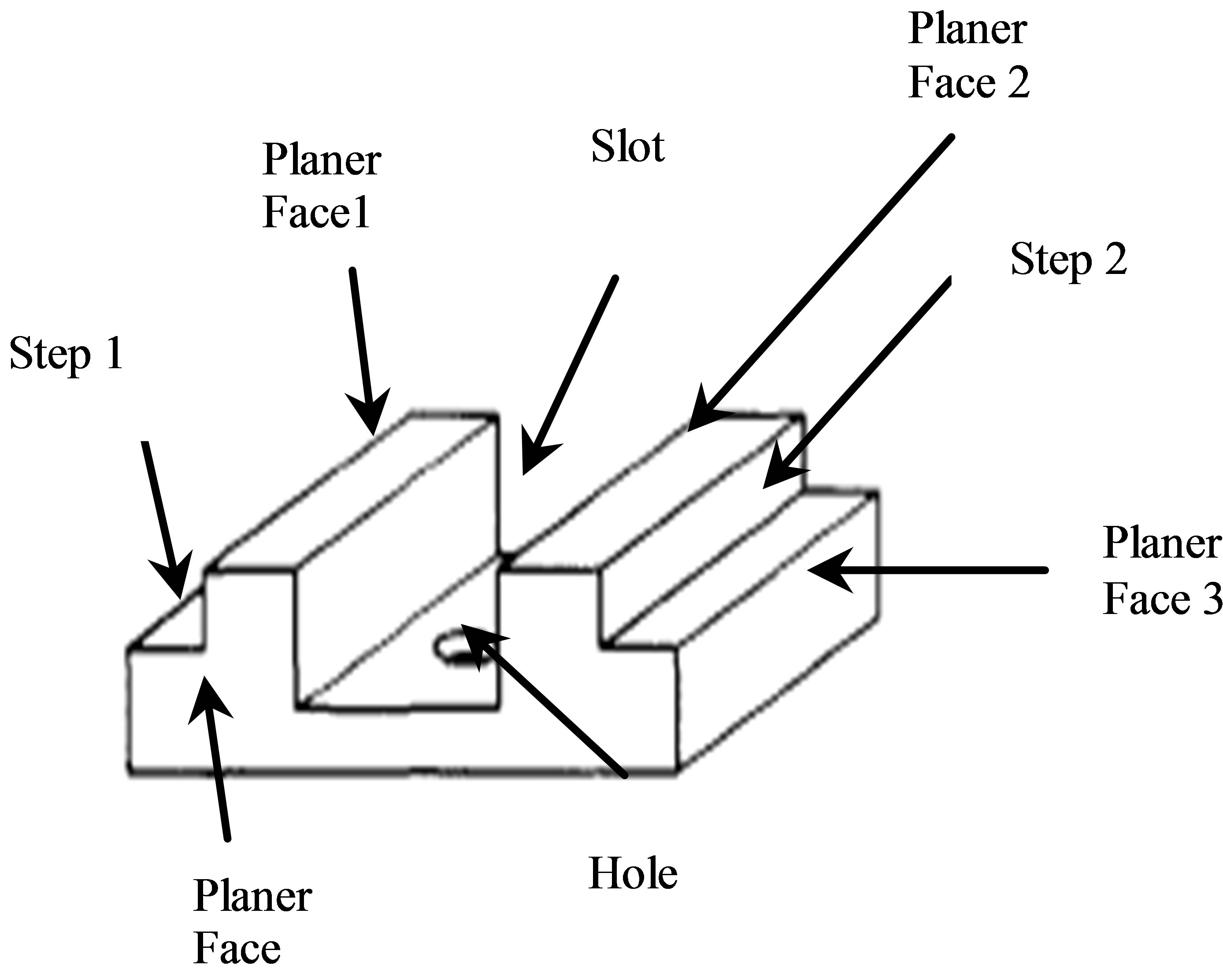
Figure 1. The features on the workpiece.
proach is becoming a very important tool for information representation in design operations. Object oriented representation is used to constitute a presentation chain, and objects are interacting on knots of that chain [11].
2. Literature Review
Eversheim and Marczinski formed a structural model designed for manufacture preparation operations [3]. Gindy and his friends presented feature based method regarding design issues as a workpiece of a CAPP system [12]. Zhang and Alting presented a product model in CIM, but that could not fully meet requirements of CAPP [1]. Need for an effective information model has been revealed as a result to be able to achieve a CAPP system which can be integrated in other systems and can fulfill its function in CIM [13]. The object paradigm enhances the expressive power of conventional database systems by providing an abstract model called a class, which describes the structure and behaviour of its instances [14]. ISO started to develop standards which include common data structures and application models for integration of CAD-CAM systems [15-19]. Studies are being carried out to develop some CAD, CAPP and CAM systems based on this approach and standards. Chep and his friends worked on an object oriented system generating a process plan for machining process of prismatic features. It was constituted from three sections as system workpiece model, information model technologic database model. While workpiece model was defining workpiece entities which form the workpiece, information model defined specialist information. Technological database defined data for the bench, tools, processability and fixture [20].
Usher and Fernandes worked on an object oriented process planning system which selects tools in process planning. They generated object models including a cutting tools database for each workpiece [21]. Hang and his friends developed an object oriented system generating a process plan for manufacturing electrical circuit cards. Processes such as Cu coating, NC processing and soldering took place as operational database objects in this system. Each module was independent and had a feature to be able to interact with each other when needed [22]. Ma and Tong proposed an object oriented system for plastic injection molding. They formed objects as channels in the injection mould [23]. Hvam and his friends worked on an object oriented system named as CRC (class, responsibility, cooperation) cards which could be used in design operations. These cards ensured the objectification of system components. System component object information was written on these cards, and components were objectified. CRC cards are being used in the design of solid liquid separation equipment by Alfa Laval Separation Company [24].
Amaitik developed a feature based, object oriented process planning system called STEP-FM for prismatic workpieces. System is composed of selection, feature generation and addition, feature specification definition and feature STEP data generation processes. Each basic shape in the system is defined by name, shape, size parameters, location and direction. Features are defined in accordance with STEP-AP standard, and workpiece is composed of these features [25]. An feature based method for design in another study. Material management features were defined to be able to control material structure in object structure. That model was developed for not only geometric features, but also for structural requirements of each feature [26]. Hybrid 3D design approach was defined by Luca and his friends. Predefined features in shape library were used to generate a template [27]. Van der Maiden and Bronsvoort developed a model for object families which they named Declarative Family of Object Models (DFOM). In this model, both geometry and topology was specified declaratively. Object family relations were modeled in DFOM [28].
Xiuzi and his friends developed the Reverse Innovative Design (RID) as a new design methodology. Feature structures were constructed from scanned 3D model, and product definition parameters were obtained from feature structures. These obtained high level product definition parameters can be reorganized later according to deformation results of feature structure [29]. Features were defined by using conditions in a process meta-model. These conditions were defined by using object constraint language (OCL). Actions were added to complete representation of features [30]. Logozzo presented a general structure for automatic and modular inference of class based object oriented language class invariables. He defined a trace-based network for classes which considers all possible orderings, variables and invocations of all methods of the class. He worked on a trace-based theorem which could be used in a fully object oriented programs [31]. Pulecchi and his friends defined basic issues regarding space craft dynamic modeling and simulation, and carried out modeling works for space craft simulation within Modelica-based modeling framework [32]. Modelica is an object oriented language which is used for modeling of complex physical system components such as mechanical, electrical, electronical, hydraulic, thermal or automated control [33]. Santos and his friends presented a new approach, Domain Specific Modeling Language (DMSL), to be used and applied in current object oriented structures. That approach is based on extension of the framework by coding layers added in framework based applications with DSML [34].
Recently, a new ISO standard called STEP NC (Standards for Exchange of Product Data for Numerical Control) is being tried to be developed to provide information model for CNC control units. These new standards are feature based and object oriented and described as ISO 10303 AP-238 and ISO 14649. These standards which also include manufacturing operations in feature and object structures provide high level information [19,35]. The goal at the end of these studies is to provide direct and complete information flow from design environment to CNC control unit (without the need to NC codes). Rameshbabu and Shunmugam developed a planning system which orders machining process for features forming a workpiece. They suggested a hybrid method including volume reduction and topologic relations on neighborhood surfaces for feature definitions. CAD data used for that study was STEP AP-203 interface file [36].
In the study, presented in this article, objectification of features forming a prismatic workpiece and coding of objects by using feature based and object oriented approaches have been achieved. CAD data used for that study was STEP AP-203 interface file [36]. Features forming the workpiece have been extracted based on data taken from STEP AP203. Then, workpieces have been objectified through classification. Objects were defined by their variables and methods. One code has been assigned to each feature object. Developed method is important by these means. Objects were classified and codes were assigned by taking the type of features and their locations on the workpiece into account. It was thought that object codes would simplify process planning significantly. Process planning can be done quite easily due to object codes [37]. Developed method was only explained for channel features in this article. Method also includes other features like hole, step and plane surface.
3. The Developed Method
Conducted study comprises the feature based-object oriented formation of geometric entities which forms prismatic workpieces and coding of objects. The approach has been based on that the workpiece generated in CAD environment consists of features. Each geometric entity forming the workpiece is a feature. The feature can also be defined as an entity which can be generated by a specific machining method. Features such as hole, layer, channel, level surface, cylindrical surface, screw, pocket, bill and radius are determined by the interpretation of STEP AP-203 CAD interface data. STEP AP-203 file generates 3D workpiece data in B-rep format, and the structure of this file is given in Figure 2 [37].
Geometric and topologic representation of Manifold solid B-rep in the structure of file has been defined in B-rep format. Outer extent of the solid is defined by closed shell. Closed shell is composed of surfaces defined by advanced faces. Each surface is represented by outer loops and inner loops where face outer bounds and face bounds are defined. Face bounds are composed of edge loops which are bounding surfaces. An edge loop is composed of directed edges. Edges respectively contain vertex points. So, geometric and topologic information can be obtained from STEP file defining 3D model. The extraction of features can be done by means of geometric information in workpiece model [17].
The scope of study covers the definition and coding of features according to their types and locations on the workpiece. The type of the feature is its geometrical shape (channel, layer, hole, level surface, radius, pah, etc.). The location of the feature is the definition of feature surface normal and feature axis direction on the workpiece.
Feature recognition process is the extraction of current features through the interpretation of STEP AP-203 file of the workpiece designed in CAD environment. This is one of the most important stages of process planning operation. Features are extracted, and raw workpiece sizes are determined through the interpretation of STEP AP-203 file structure given in Figure 2.
Topologic relations between surfaces are analyzed while features are being extracted, and type of the feature is assigned. Extracted feature are coded as their locations are interpreted. General algorithm of the developed method has been given in Figure 3.
In feature based modeling, features are structured in a class systematically according to their SUPER and SUB specifications. Developed method includes general definitions for entities like channel, hole, pocket, bill and level surface on the highest level of SUPERTYPE features. General entity definitions at the highest level have SUPTYPE features on subsequent lower levels. For example; a channel SUPERTYPE feature has open and/or pocket shaped SUBYPE feature levels.
Types and locations of features are fundamental in the assignment of object oriented class levels. Every feature which is forming a workpiece also forms an object, and has a code. The assignment of codes is explained for channel feature in the following chapter. It is evaluated that object codes will be very helpful during operation planning. Because it is easier to make production decisions after every feature with high level information definition is redefined and coded with object rationale.
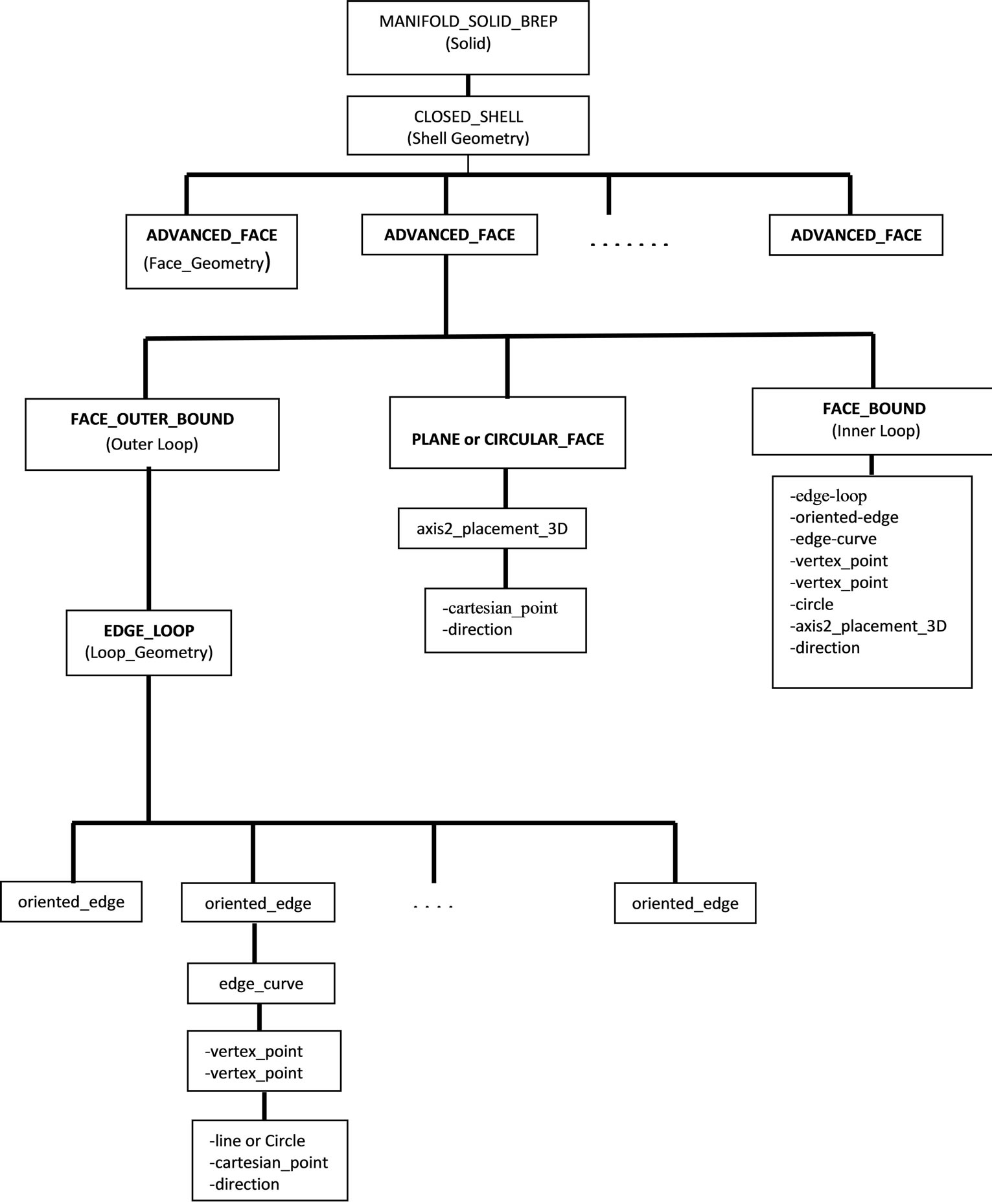
Figure 2. The file structure of STEP AP-203.
3.1. Object Modeling and Coding of Channel Feature
In this section, feature and object based generation and coding of a channel feature has been explained as an example. Figure 4 demonstrates the definition of channel feature. The highest object class level is the highest class for channels, and represented by code S (Slot). When manufacturing technologies are considered, it can be seen that one channel has four types on its first sub level. These are square, round, V (Vee) and T (Tee) channel types. This class level is the first SUBTYPE class level of highest SUPERTYPE class of channel feature according to object oriented definition. Channel classes at this level are represented by SQ for square channel, SR for round channel, SV for V channel and ST for T channel.
Second SUBTYPE class level is assigned according to the direction of channel base surface normal in Cartesian coordinate system. These can be in six directions as +X, +Y, +Z, –X, –Y and –Z. Numbers 1, 2, 3, 4, 5 and 6 consecutively represent these directions. The axis direction of the channel is considered for the third SUBTYPE class level.
Second SUBTYPE class level is assigned according to the direction of channel base surface normal in Cartesian coordinate system. These can be in six directions as +X, +Y, +Z, –X, –Y and –Z. Numbers 1, 2, 3, 4, 5 and 6 consecutively represent these directions. The axis direction of the channel is considered for the third SUBTYPE class level.
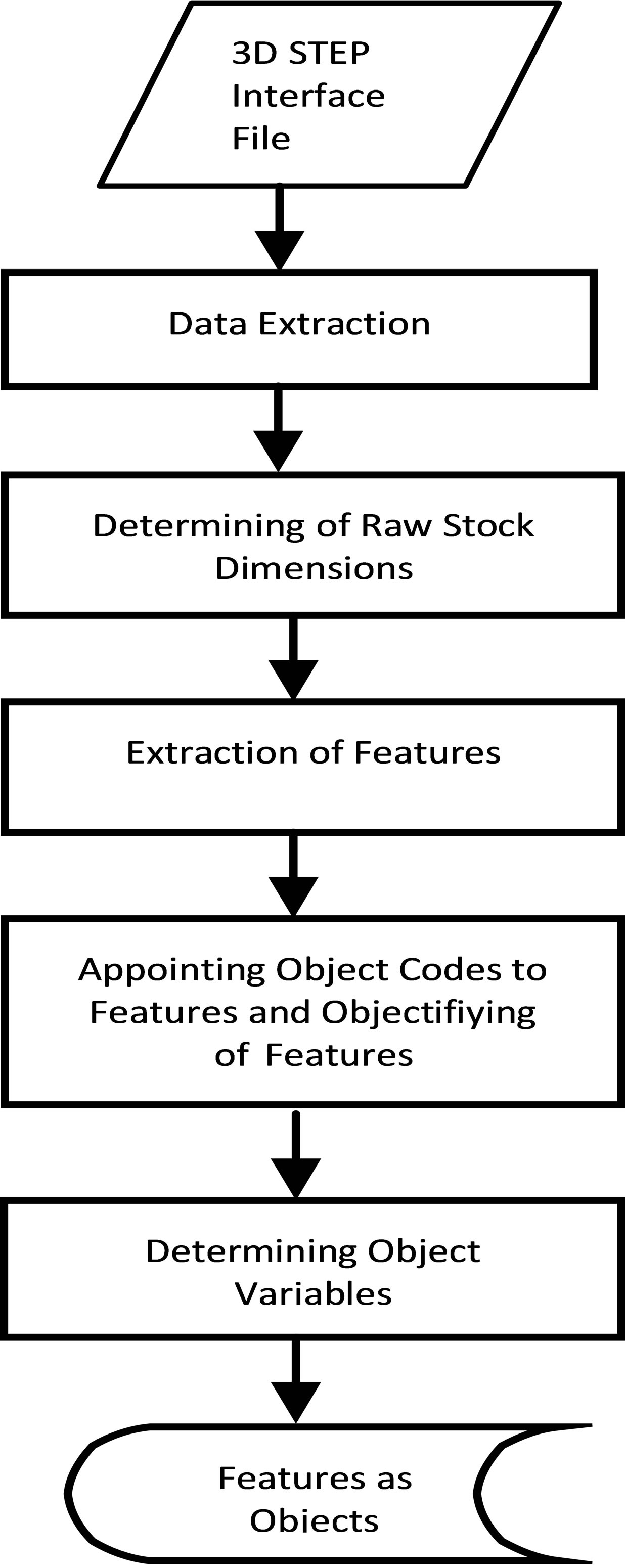
Figure 3. Recognizing, coding and objectifiying of the features.
For example; a channel which is open at +Z direction at the second class level can have an axis in Y or X direction. Of course, it is possible that channel axis can have an angled value in X or Y direction. That is why channels at the third level are defined by 3 characters. While the first character represents the base axis direction that is related to channel axis, other two characters represent the angle between the channel and the base axis. The consideration for the fourth class level is states of channel as open throughout, right closed and left closed. Channels which are closed from both right and left are pocket features, and defined in a different feature class. At that class level, (R) character shows that the axis direction is closed from positive side, and (L) character shows that the axis direction is closed from negative side. Open throughout channel is represented by code T.
Channel feature given in Figure 5 as an example has been coded with SQ3Y00L according to object structuring and coding logic. The evaluation of this object in process planning will be like that. Code S of the object shows that the feature is a channel, and code Q tells that the channel is square type. The third character of code chain which is 3 states that the channel is open at +Z direction in Cartesian coordinate system and the fourth character which is Y demonstrates that the channel axis is in Y base axis direction. 00 values as fifth and sixth characters define the angle between channel axis and Y axis as 0. The last code in the code chain, the seventh character code L, states that the channel is closed from –Y direction on the workpiece.
3.2. Use of Object Structure and Object Codes in Process Planning
Object oriented systematic modeling of features forming the workpiece and the assignment of codes provides a great help in process planning. The interpretation of interface file taken from CAD environment, the assignment of codes after features have been extracted and operation of process plan according to these codes are a big advantage for manufacture decision making. Because features are systematically defined as objects, and coded. Also, high level information which is called variables and methods defining the feature is defined in the object. A feature with its code and variables and methods involved in object structure submits a great amount of high level information to the process plan. Process plan interprets high level information involved in objects instead of low level information such as point, corner, line or round, and makes manufacture decisions without complexity and ambiguity.
Variables and methods which belong to the feature placed in the object are defined through the generation of an feature as an object. Variables are main characteristics of an feature. For example; variables of an feature represented in object information are; material of the channel, reference point on the workpiece (RP), width (w), height (h), length (l), tolerances and channel surface quality (Ra) values. Methods are program components which determine variables by either interpreting CAD interface file or interacting with the user. While methods can determine geometric object variables from CAD data, can consult with the user for non-geometric variables (For example, surface quality and material type, etc.). Object codes of every object define the type and location of the object in the beginning. Object information of the object with code SQ3Y00L given in Figure 5 as an example is as follows: What process plan interprets from object code is that there is a channel feature on the workpiece which is open in +Z direction with 0 degree angle along Y axis and closed from –Y direction.
After determination of that feature on the workpiece from CAD interface file, the object code has been assigned as SQ3Y00L. Then, geometric variables are also determined from CAD interface file. Length (l), length
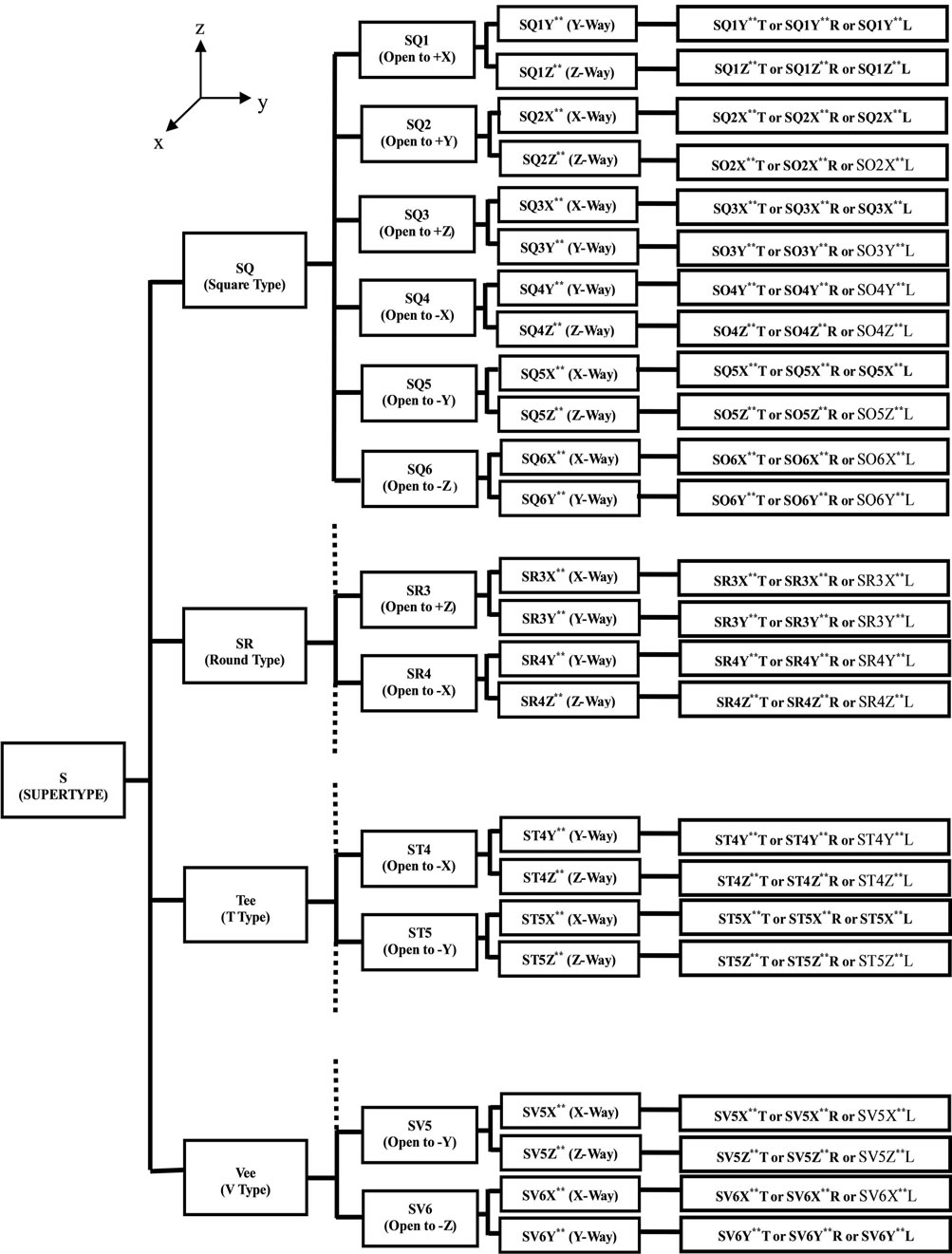
Figure 4. The object classes and codes of the slot feature.
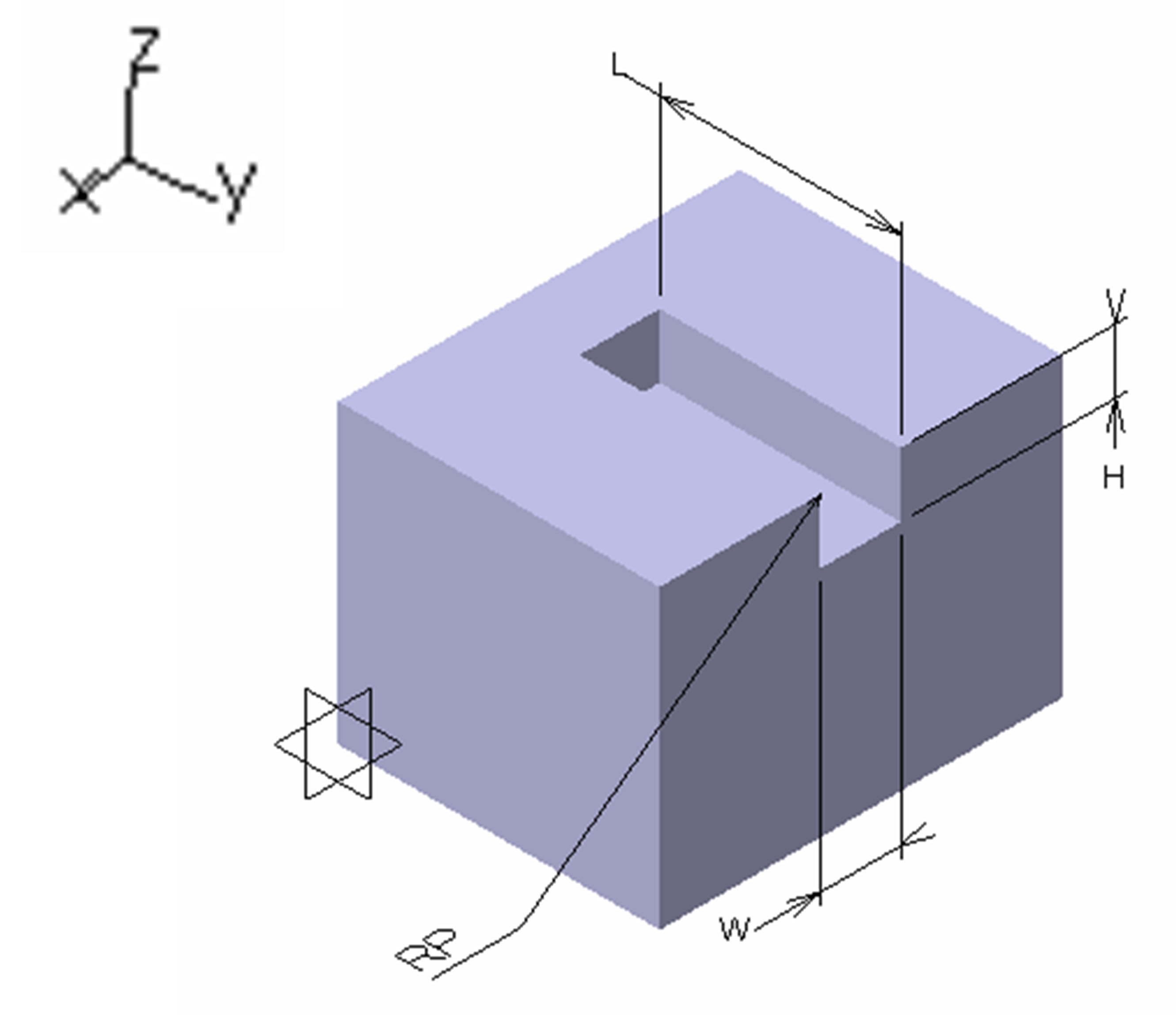
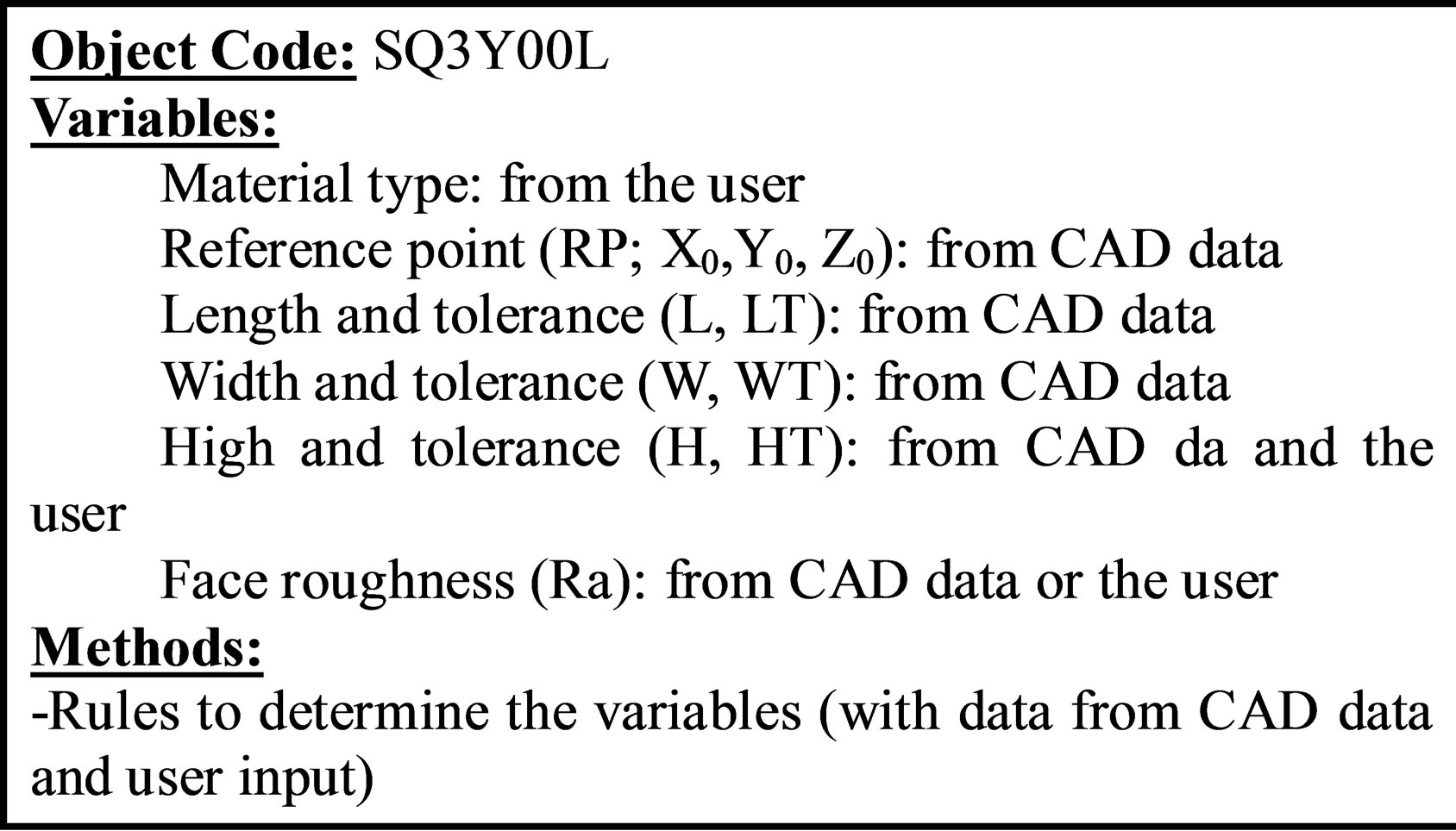
Figure 5. SQ3Y00L object.
tolerance (lt), width (w), height (h), height tolerance (ht) and reference point (xo, yo, zo) are geometric variables. Methods are the rules to determine variables. Because material type, tolerance, surface quality values cannot be obtained from CAD interface file, these information are requested from the user. Material type is defined for the first feature entered, and the same material type is assigned to other features automatically by the system. So, SQ3Y00L coded object is generated with all the information required in manufacturing. As a result, SQ3Y00L coded feature is generated as an object.
Method has been developed as feature based and object oriented. As a result, high level information for the feature required for manufacturing has been capsulated in the object. Object code defines the type and location of the object on the workpiece. That type of modeling is a big advantage for CAPP because CAPP easily determines and orders operations according to object codes. Decisions required for operation parameters are determined by object variables. General flow graphic of process plan for the interpretation of objects is in Figure 6. The workpiece binding-support surfaces and operations are determined according to the features forming the workpiece. The cutting tool is selected according to the material type. The finish processes is determined according to the surface quality and tool paths is determined according to object variables. The method presented in this article is only explained for channel features. Developed method also includes features like hole, step, pocket, boss, radius, pah and screw. Additional feature types can be added in the system.
4. Application Sample
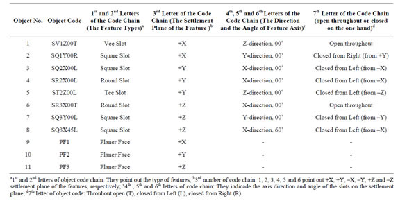
The workpiece in Figure 7 is given as an example with its forming features. An object code was assigned to each feature extracted from STEP AP-203 interface file. Raw workpiece sizes were determined based on geometric values of border features. Table 1 summarizes object code information and code assignment logic of the workpiece given in Figure 7. That information is used by
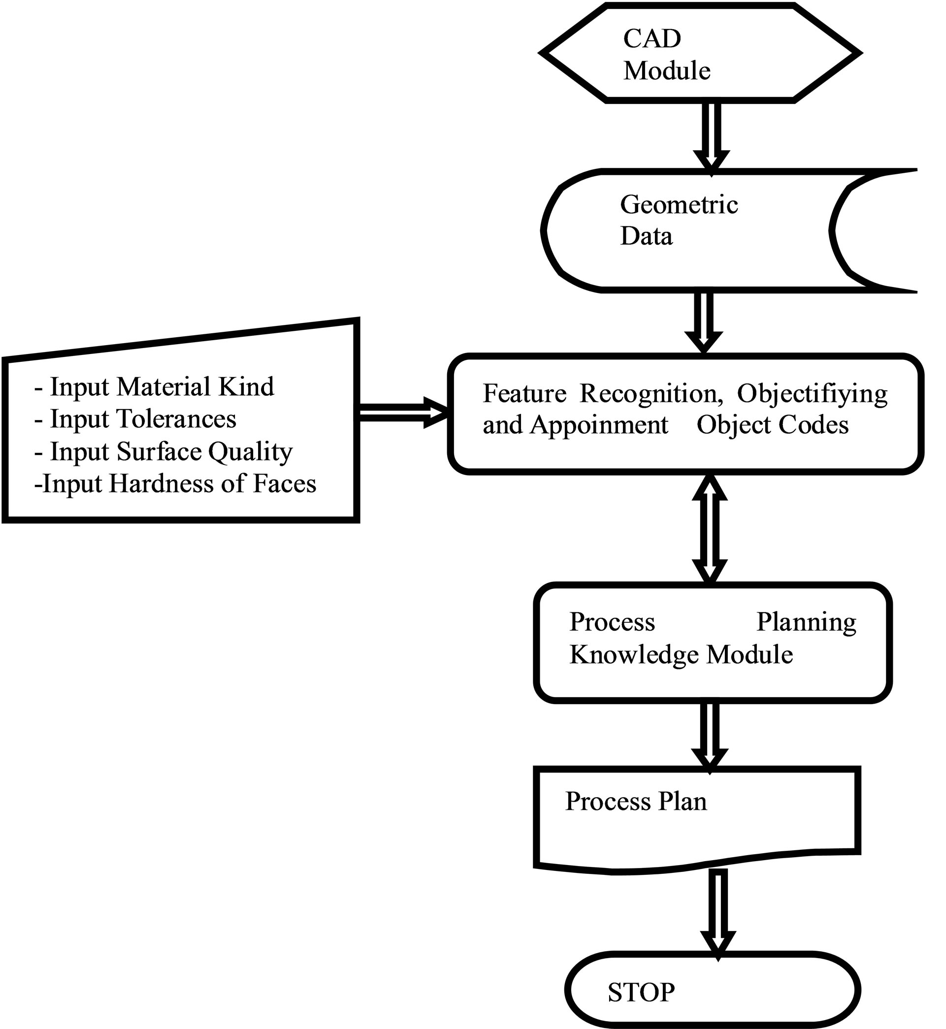
Figure 6. The use of object codes in the process planning.
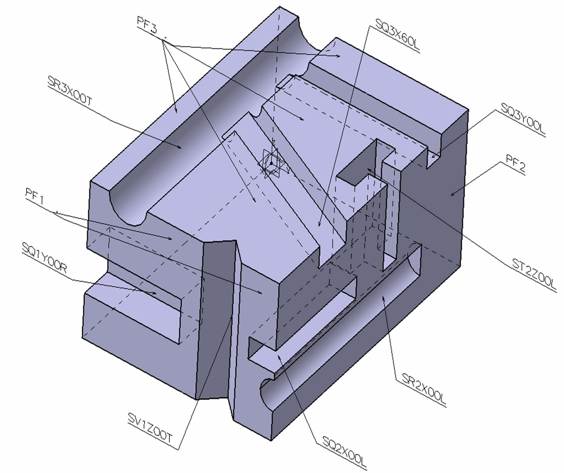
Figure 7. The example workpiece.
CAPP software.
The use of the developed method in a CAPP system has been demonstrated in Figures 8 and 9. User interface of CAPP is given in Figure 8. At that stage, codes have been assigned to each feature determined by CAPP feature recognition module. Material type is defined for the first feature, and the same value will be assigned to other features. The surface roughness value (Ra) will be assigned as 6.3 μm by the system automatically if not entered by the user. Process plan makes manufacturing decisions according to object codes and variables.
The process plan generated by process planning system by using objects and object codes is shown in Figure 9. Process plan determines operations needed for each feature. At this stage, planning is made for all features on the workpiece by researching feature codes determined before. Process plan determines raw material sizes, operation sequence number, operation name, pass number in each operation, cutting edge, reference point for each operation, processing regime and operation time. Here can be seen that each operation belongs to a feature. Because information needed to determine operational information has been capsulated as an object in every feature, process plan easily determines the manufacturing information required by each operation.
5. Results
In this paper, a method for CAD/CAM integration is constructed as the feature based and object oriented. This method can be used for process planning during feature recognition and making manufacturing decisions. STEP
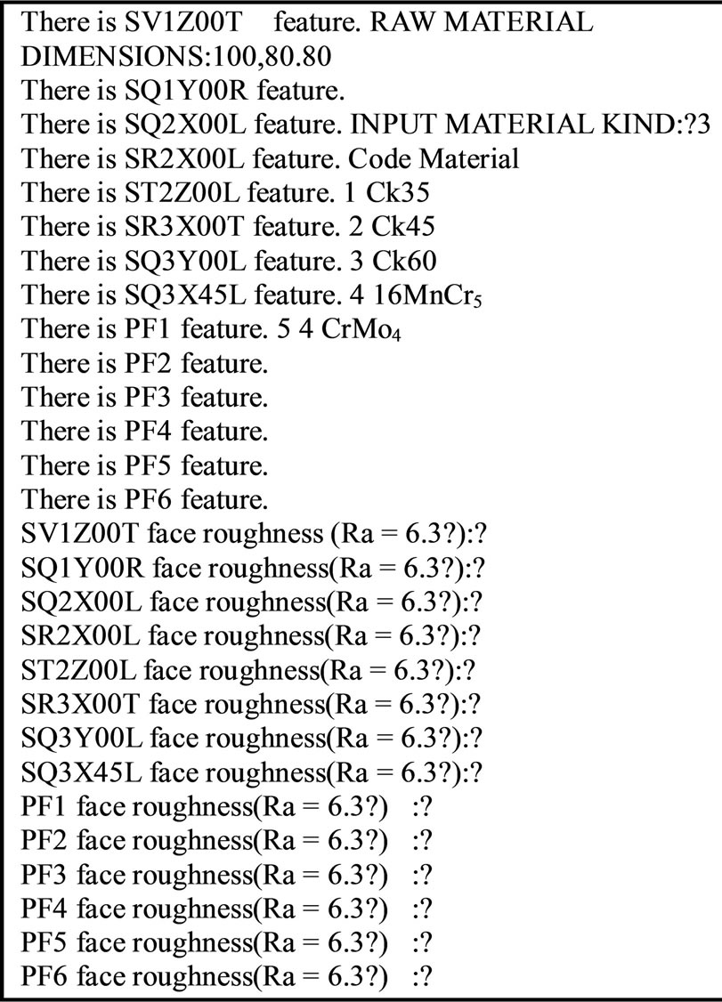
Figure 8. User interface of feature recognition.
interface file from CAD systems are analyzed, and features forming the workpiece are extracted. Extracted features are classified object orientedly according to type and their location on the workpiece. An object code is assigned to every feature in the object class. So, object code defines the type and the location of the feature on the workpiece. Then, each feature is defined with object
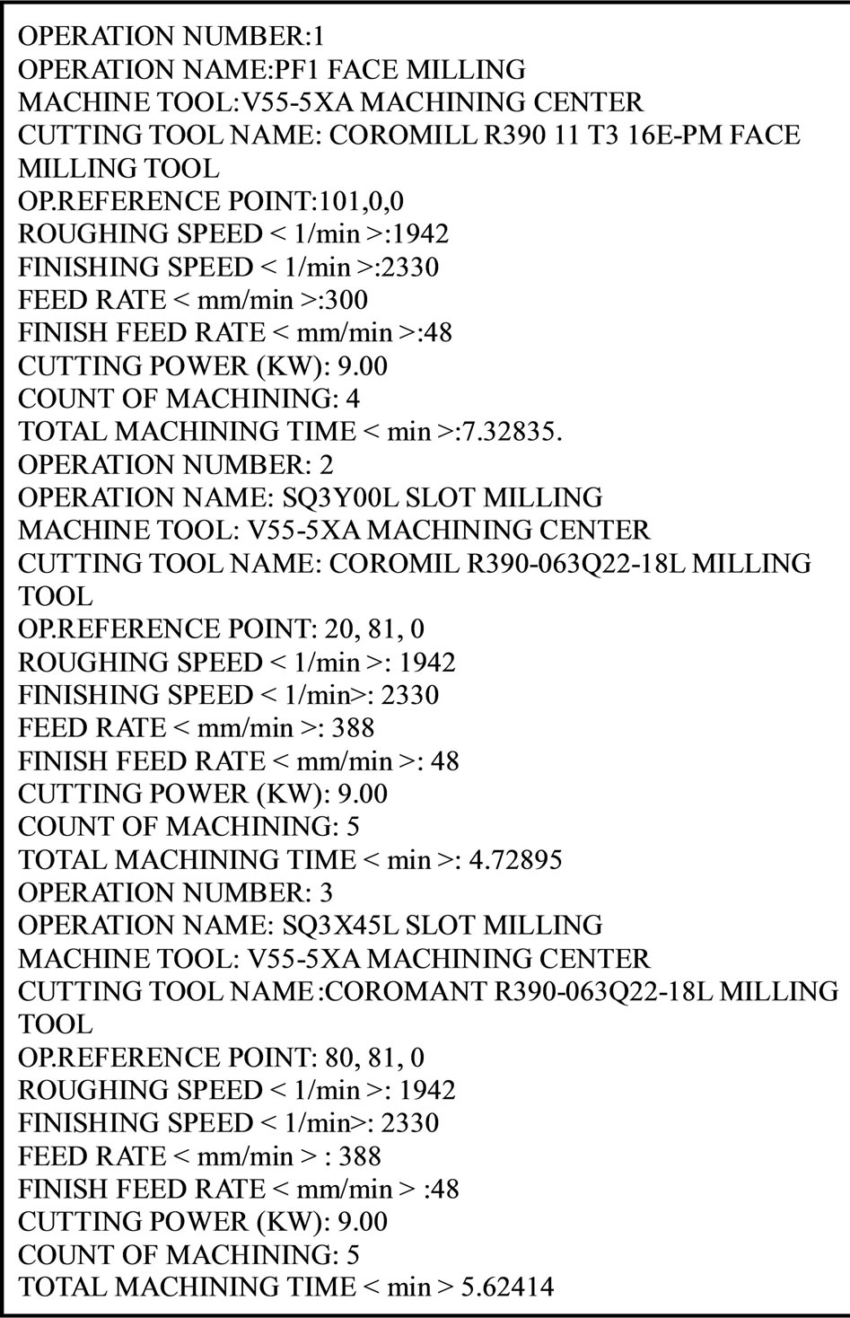
Figure 9. Output of process plan.
logic, and methods are determined. Process planning system see features forming the workpiece with their codes while planning manufacturing, and makes a process plan by interpreting variables included in each feature. The object coding logic which is developed in this method is original. It is apparent that object codes will be very advantageous for process planning systems. When the process plan picks up the object code of each feature, it can analyze the feature type and location, and also determine operations which belong to the feature, operation sequence, reference points, tool paths, process regimes, process time for each operation, etc. by evaluating variables in the object. As a result, it is determined and proved that the objectification and object codes have a great advantage in process planning operations.
6. Conclusion
At the CAD and CAM integration, feature based and object oriented part design will facilitate the works of design and manufacturing engineering. Furthermore, process planning object codes, which were developed at this time, are providing significant advantages. These methods can be used for the complicated shaped parts.
REFERENCES
- H. C. Zhang and L. Alting, “Computerized Manufacturing Process Planning Systems,” Chapman & Hall, New York, 1994, pp. 16-18.
- A. Hoda, E. El Maraghy, B. J. Agerman, W. H. Davies, W. El Maraghy, D. G. Eversheim, I. Halevi, H. B. Ham, H. J. Jasperse, A. Y. C. Kals, G. Nee, V. Sohlenius, H. K. Tipnis, C. A. Tönshoff, R. Van Luttervelt, H. P. Weill and F. J. Weindahl, “Evolution and Future Perspectives of CAPP,” CIRP Annals-Manufacturing Technology, Vol. 42, No. 2, 1993, pp. 739-751.
- W. Eversheim, G. Marczinski and R. Cremer, “Structured Modeling of Manufacturing Processes as NC-Data Preparation,” CIRP Annals, Vol. 40, No. 1, 1991, pp. 429-432. http://dx.doi.org/10.1016/S0007-8506(07)62022-8
- M. Duhwan, H. Soonhung, K. Junhwan and O. Youchon, “A Set of Standard Modeling Commands for the History-Based Parametric Approach,” Computer-Aided Design, Vol. 35, No. 13, 2003, pp. 1171-1179. http://dx.doi.org/10.1016/S0010-4485(03)00022-8
- P. B. Berra and M. M. Barash, “Investigation of Automated Planning and Optimization of Metal Working Processes,” Report 14, Purdue Laboratory for Applied Industrial Control, 1968.
- C. H. Link, “CAPP, CAM-I Automated Process Planning System,” Proceedings of the 13th Numerical Control Society Conference, Cincinnati, March 1976, pp.
- D. K. Allen, “Process Planning Primer,” 19th CIRP International Seminar on Manufacturing Systems, Penn State University, Pennsylvania, 1987.
- T. Lenau and L. Alting, “XPLAN—An Expert Process Planning System,” Proceedings of the 2nd International Expert Systems Conference, London, 1986.
- L. Alting and H. C. Zhang, “Computer Aided Process Planning: The State-of-the-Art Surrey,” International Journal of Production Research, 1989, pp. 553-585. http://dx.doi.org/10.1080/00207548908942569
- A. Shah, F. Fotouhi, W. Grosky and J. Al-Muhtadi, “Operators of the Temporal Object System and Their Implementation,” Information Sciences, Vol. 158, 2003, pp. 37- 68. http://dx.doi.org/10.1016/j.ins.2003.08.004
- D. C. Chatfield, T. P. Harrison and J. C. Hayya, “SCML: An Information Framework to Support Supply Chain Modeling,” European Journal of Operational Research, Vol. 196, No. 2, 2009, pp. 651-660. http://dx.doi.org/10.1016/j.ejor.2008.03.027
- N. N. Z. Gindy, X. Huang and T. M. Ratchev, “Feature-Based Component Model for Computer-Aided Process Planning Systems,” International Journal of Computer Integrated Manufacturing, Vol. 6, No. 1-2, 1993, pp. 20-26.
- X. G. Ming, K. L. Mak and J. Q. Yan, “A PDES/STEPBased Information Model for Computer-Aided Process Planning,” Robotics and Computer-Integrated Manufacturing, 1998, pp. 347-360. http://dx.doi.org/10.1016/S0736-5845(98)00023-4
- S. Coulondre and T. Libourel, “An Integrated ObjectRole Oriented Database Model,” Data & Knowledge Engineering, Vol. 42, No. 1, pp. 113-141. http://dx.doi.org/10.1016/S0169-023X(02)00059-9
- ISO 10303-1, “Industrial Automation Systems and Integration-Product Data Representation and Exchange-Part 1,” Overview and Fundamental Principles, 1994.
- ISO 10303-11, “Industrial Automation Systems and Integration-Product Data Representation and Exchange-Part 11: Description Methods,” The EXPRESS Language Reference Manual, 1994.
- ISO 10303-203, “Industrial Automation Systems and Integration-Product Data Representation and ExchangePart 203,” Application Protocol: Configuration Controlled 3D Designs of Mechanical Parts and Assemblies, 1994.
- ISO 10303-224, “Industrial Automation Systems and Integration-Product Data Representation and ExchangePart 224,” Application Protocol: Mechanical Product Definition for Process Plans Using Machining Features, 2001.
- ISO/DIS 10303-238, “Industrial Automation Systems and Integration-Product Data Representation and ExchangePart 238,” Application Protocols: Application Interpreted Model for Computerized Numerical Controllers, 2003.
- A. Chep, L. Tricarico, P. Bourdet and L. Galantucce, “Design of Object Oriented Database for Definition of Machining Operation Sequences of 3D Workpieces,” International Journal of the Computer Integrated Manufacturing, Vol. 34, No. 2, 1998, pp. 257-279.
- J. M. Usher and K. J. Fernandes, “An Object Oriented Application of Tool Selection in Dynamic Process Planning,” International Journal of the Computer Integrated Manufacturing, Vol. 37, No. 13, 1999, pp. 2879-2894.
- W. L. Hang, Y. T. Hon, H. S. C. Alan and I. K. Hui, “Object Oriented Knowledge Based Computer Aided Process Planning System for Bare Circuit Boards Manufacturing,” Computers in Industry, Vol. 45, No. 2, 2001, pp. 137-153.
- Y. S. Ma and T. Tong, “Associative Feature Modeling for Concurrent Engineering Integration,” Computers in Industry, Vol. 51, No. 1, 2003, pp. 51-71. http://dx.doi.org/10.1016/S0166-3615(03)00025-3
- L. Hvam, J. Riis and B. L. Hansen, “CRC Cards for Product Modeling,” Computers in Industry, Vol. 50, No. 1, 2003, pp. 57-70. http://dx.doi.org/10.1016/S0166-3615(02)00143-4
- S. Amaitik, “Development of a Step Feature Based Intelligent Process Planning System for Prismatic Parts,” Ph.D. Thesis, Middle East Technical Univesity, Ankara, 2005.
- K. Samanta and B. Koc, “Feature Based Design and Material Blending for Free-Form Heterogeneous Object Modeling,” Computer-Aided Design, Vol. 37, No. 3, 2005, pp. 287-305. http://dx.doi.org/10.1016/j.cad.2004.03.005
- D. L. Luca, P. Veron and M. Florenzano, “Reverse Engineering of Architectural Buildings Based on a Hybrid Modeling Approach,” Computers & Graphics, Vol. 30, No. 2, 2006, pp. 160-176, http://dx.doi.org/10.1016/j.cag.2006.01.020
- H. A. Van der Meiden and W. F. Bronsvoort, “Solving Topological Constraints for Declarative Families of Objects,” Computer Aided Design, Vol. 39, No. 8, 2007, pp. 652-662. http://dx.doi.org/10.1016/j.cad.2007.05.013
- X. Z. Ye, H. Z. Liu, L. Chen, Z. Y. Chen, X. Pan and S. Y. Zhang, “Reverse Innovative Design—An Integrated Product Design Methodology,” Computer Aided Design, Vol. 40, No. 7, 2008, pp. 812-827. http://dx.doi.org/10.1016/j.cad.2007.07.006
- S. A. Ajila and A. B. Kaba, “Evolution Support Mechanisms for Software Product Line Process,” The Journal of Systems and Software, Vol. 81, No. 10, 2008, pp. 1784- 1801.
- F. Logozzo, “Class Invariants as Abstract Interpretation of Trace Semantics,” Computer Languages, Systems & Structures, Vol. 35, 2009, pp. 100-142.
- T. Pulecchi, F. Casella and M. Lovera, “Object-Oriented Modeling For Spacecraft Dynamics: Tools and Applications,” Simulation Modeling Practice and Theory, Vol. 18, No. 1, 2010, pp. 63-86. http://dx.doi.org/10.1016/j.simpat.2009.09.010
- M. Otter, “Modellica Overwiev,” 2009. https://www.modelica.org/education/educational-material/lecture-material/english/ModelicaOverview.pdf
- A. L. Santos, K. Koskimies and A. Lopes, “Automating the Construction of Domain-Specific Modeling Languages for Object-Oriented Frameworks,” The Journal of Systems and Software, Vol. 83, No. 7, 2010, pp. 1078-1093. http://dx.doi.org/10.1016/j.jss.2010.01.047
- ISO 14649-1, “Data Model for Computerized Numerical Controllers: Part 1,” Overview and Fundamental Principles, 2003.
- V. Rameshbabu and M. S. Shunmugam, “Hybrid Feature Recognition Method for Setup Planning from STEP AP-203,” Robotics and Computer-Integrated Manufacturing, Vol. 25, No. 2, 2009, pp. 393-408. http://dx.doi.org/10.1016/j.rcim.2007.09.014
- I. Celik, “Knowldege Based Process Planning System for Workpieces to be Produced at Machining Center,” Ph.D. Thesis, Selcuk University, Konya, 2004.
NOTES
*Corresponding author.