Open Journal of Civil Engineering
Vol. 3 No. 3 (2013) , Article ID: 36392 , 7 pages DOI:10.4236/ojce.2013.33020
Progressive Collapse of RC Frames Due to Heavy Impact Loads of Tsunami
1Department of Civil Engineering, Azarbaijan Shahid Madani University, Tabriz, Iran
2College of Engineering, Northeastern University, Boston, USA
Email: keyvani@azaruniv.edu, Lkeyvani@neu.edu
Copyright © 2013 Abdullah Keyvani, Leila Keyvani. This is an open access article distributed under the Creative Commons Attribution License, which permits unrestricted use, distribution, and reproduction in any medium, provided the original work is properly cited.
Received July 3, 2013; revised August 3, 2013; accepted August 10, 2013
Keywords: Collapse; Impact Loads of Tsunami; Material Nonlinearity; Fiber Elements; RC Frames
ABSTRACT
Progressive collapse is a relatively rare event, as it requires both an abnormal loading to initiate the local damage and a structure that lacks adequate continuity, ductility and redundancy to resist the spread of damage. However, significant casualties can result when collapse occurs. Heavy impact loads due to tsunami against building can be one of the scenarios of progressive collapse during tsunami disaster. Since progressive collapse includes material and geometry nonlinearity during collapse propagation, in the present research capability of 2 models for the material nonlinearity in simulating actual behavior of structures during collapse is compared with recent experimental results of a Reinforced Concrete (RC) frame. The results demonstrate that a material nonlinearity model, that is based on the idealized component load-deformation behavior, is not a proper representation for the real behavior of structures during progressive collapse and is so conservative.
1. Introduction
While earthquakes and tsunamis are inevitable forces of nature, it is possible to be better prepared for them so that the damage to infrastructure can be minimized. To save lives, efficient tsunami-warning systems need to be put in place for the evacuation of people from coastal areas. The physical, economic and financial loss to the coastal community can also be reduced by having tsunami resistant designs for houses and other infrastructure in the region.
The potential catastrophic effects of tsunami-induced loading on the infrastructure in the vicinity of shorelines have been brought to the fore by recent global events. However, state of-the-art building codes remain silent or provide conflicting guidance on designing near shoreline structures in tsunami-prone areas. This paper focuses on tsunami-induced impact loading and its effect on progressive collapse of structures. The Asian tsunami of 26 December 2004 showed the catastrophic devastation that could be caused by a tsunami to human lives, infrastructure and economy [1,2]. The tsunami claimed more than 220,000 lives and made almost 800,000 people homeless. The total economic cost of the catastrophe is estimated to be more than £7.5 billion.
Heavy impact loads due to tsunami against building can be one of the scenarios of progressive collapse during tsunami disaster. Progressive collapse as one of the important threats against the safety and stability of structures has attracted attention of researchers and structural designers in recent decades. Progressive collapse is defined as the spread of an initial local failure from element to element eventually resulting in collapse of an entire structure or a disproportionately large part of it. The initial cause of the local failure can be man-made such as explosions or natural such as earthquake [3].
Progressive collapse is a relatively rare event, as it requires both an abnormal loading to initiate the local damage and a structure that lacks adequate continuity, ductility, and redundancy to resist the spread of damage [4]. However, significant casualties can result when collapse occurs.
Up until then, standards had no emphasis on systemlevel behavior of structures. The British Standards required consideration of progressive collapse in buildings taller than five stories and provisions for structural ties. In the 1970s, the US Department of Housing and Urban Development’s Operation Breakthrough examined the problem of progressive collapse in the US, focusing on concrete panel structures [5]. According to 1970s researches Alternate Load Path Method (ALP) is recommended as a direct design method for analyzing progressive collapse potential, in which the behavior of structures were assessed after removing one and/or some of primary members from building [6]. Starting in the 1980s, design standards in the US, such as the ACI code, began to implement structural integrity provisions [5]. Additionally, ASCE [7] implemented some provisions for general structural integrity. However, these standards did not include specific provisions for resistance against progressive collapse [5].
Most of the researchers have evaluated the progressive collapse in a partial-level rather than system-level either analytically or experimentally. However, due to the system-level behavior of collapse, the entire members of a structure deal with the stress transition and/or collapse. Therefore, this research particularly deals with the progressive collapse of an RC frame as system-level collapse due to heavy impact loads of tsunami.
The accuracy of any modeling effort to assess the risk of progressive collapse of a structure depends heavily on how well the material behavior is captured [5]. That is why this research is to investigate the reliability and accuracy of representative models in simulating material nonlinearity for progressive collapse of an RC frame. Frame model is based on a recent experimental research on system-level progressive collapse. The analytical results of material nonlinearity models in simulating collapse of the RC frame are compared with the experimental results. In addition, capability of one of the common FE software (SAP NL) in modeling and verifying the experimental results is assessed.
2. Tsunami Impact Loadings
Understanding tsunami wave-loading on coastal houses is important to improve the design of coastal structures. There is a significant body of research work on the wave impact on vertical walls and therefore columns [8-13]. While these can give some guidance on the magnitude of tsunami wave loading on coastal houses, the three dimensional nature of house structures and the propagation of a tsunami wave around and through houses make wave impact very different to that on a vertical wall and columns. The Asian tsunami has shown the severe damage that tsunami loading can inflict on various structures [14].
The first loading combination (initial impact) considers surge and debris impact forces as the main lateral load components. This represents the first impact of the tsunami bore. The second scenario (post impact) includes debris impact, hydrodynamic, and hydrostatic forces as the lateral loads. Note that the net hydrostatic forces typically provide an insignificant lateral load to the structure as a whole. However, the hydrostatic force may be more important in the evaluation of loads on an individual element. In addition to the lateral loads, a buoyant force component is included in the post impact event. This force can cause stability problems, including a reduction in the sliding and overturning resistance of a structure. Furthermore, consideration should be given to the rapid rising water level within a structure that has been flooded. This phenomenon can result in significant uplift forces on flooring elements [15].
A Japanese design method for tsunami wave loading considers both the static and dynamic loads together [16]. The force per unit length of the wall is taken as an equivalent hydrostatic load with three times the inundation depth, H, for a tsunami wave with no break-up (Figure 1(a)).
This leads to a resultant force equal to nine times the hydrostatic force of inundation depth H. In the case of wave break-up, an additional triangular pressure distribution to a height of 0.8 H with base pressure of 2.4 ρgH (where ρ is density of the water and g is the gravity constant) is superimposed (Figure 1(b)). This leads to an equivalent force of around 11 times the hydrostatic force of inundation depth H. If the height of the building is less than 3 H, then the pressure distribution is truncated at the height of the building.
The US Army’s coastal engineering research centre’s technical note also provides guidance on wave force on a shoreward vertical wall [17]. This guidance is based on the work of two researchers [18,19]. The tsunami wave force per unit length of the wall is given as a sum of hydrostatic force and dynamic force. It was shown that, for most cases, the tsunami wave force is 4.5 ρgH2. This is in line with the Japanese design method as it is nine times the hydrostatic force of inundation depth H.
The US Federal Emergency Management Agency’s [20] coastal construction manual provides the total wave
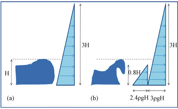
Figure 1. Tsunami wave pressure based on the Japanese design method. (a) An unbroken wave is equivalent 3 times of hydrostatic pressure; (b) About 11 times if the wave breaks.
load (hydrodynamic and hydrostatic) on a vertical wall (height ≥ 2.2 H) of a coastal residential building to be about 11 times the hydrostatic force with inundation depth H.
Another way to consider the tsunami wave loading is to consider it as consisting of three components [21]:
1) Hydrostatic,
2) Hydrodynamic and,
3) Impact loading.
An important part of the hydrodynamic loading depends on the drag coefficient CD, which varies between 1.25 and 2 [22]. FEMA recommends a drag coefficient of 1.25 for width-to-inundation-depth ratios of 1 to 12. If the wave is taken to be normal to the house wall, hydrodynamic loading per unit length of the wall can be shown to be five times that of the hydrostatic force. Impact loading can be shown to be a function of the impact coefficient Ct.
It can be deduced from a research in Japan and New Zealand [23] that Ct depends on the angle of wave front at impact, and its value is typically between 1.7 and 3 as bore angles vary from 22.5˚ to 45˚. The impact force based on the above values of Ct can be shown to be 12 times that of the hydrostatic force. In conclusion, the literature review suggests that the overall loading per unit width can be as high as 18 times the hydrostatic force. However, this is an upper limit and the actual value may be lower. More research is needed to understand the impact loading on houses as the past research has concentrated on vertical walls without openings such as doors or windows.
3. Analytical Models
In the present research it is assumed that due to the impact loads of tsunami one column of an RC frame collapses, then the stability of the frames needs to be evaluated. A four-bay and 3-story RC frame structure was selected as a analytical model for considering the phenomenon of impact loads of tsunami disaster. To verify the results and reliability of the research, the specifications of the frame was based on an experimental model from the research of Yi et al. [24]. Experimental model of Yi is one of rare and the most recent experimental researches in assessment of system-level progressive collapse therefore verification of analysis can be confirmed in comparative method.
The experimental model is a four-bay and eight-story RC frame structure which was designed in accordance with the concrete design code of China. A third-scale model of the lower three stories of the original frame was constructed for the collapse experiment.
In the analytical model (Figure 2), the frame is in equilibrium position with applied forces. In Push-down analysis method of this research, the reaction of middle
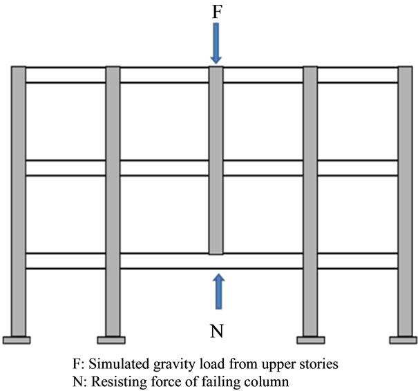
Figure 2. Loading configuration of analytical model.
column was applied in opposite direction of force N statically in displacement-controlled manner to simulate the column removal statically. This approach of member removing for simulating progressive collapse is suggested in literatures [26,27].
According to the experimental results, at a displacement of 456 mm or a beam end distortion angle of 10.3 degrees, the steel bars near the end of the first floor beam adjacent to the middle column ruptured. In the experimental analysis, failure resulting from progressive collapse of the RC frame was ultimately controlled by the rupture of the reinforcing steel bars in the floor beams [24]. Clearly, this is different from the normal limit state for beam bending, which is controlled either by crushing of concrete in compression or shear failure, i.e. for a better understanding of the progressive collapse behavior, experimental results of Yi [24] and the analytical results of this research are not continued beyond the concrete crush.
Progressive collapse consists of both material and geometrical nonlinearity [28]. In order to simulate the material nonlinearity during collapse, two methods were used. The results were compared with the experimental results, and the advantages and disadvantages of both models were discussed. The models are:
1) Assigning plastic hinge for members based on the Idealized Component Load-Deformation curve of FEMA 356 [25]. This method is suggested as one of the common methods in DoD [6]. Moment-curvature (M3-q) curve was assigned for plastic hinge of beams and axialmoment interaction (P-M) for columns (Figure 3).
2) Assigning Fiber Element Hinges in accordance with designing details of member sections and stress-strain relationship of materials. According to Figure 4, in this
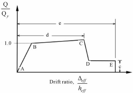
Figure 3. Idealized component of load-deformation relationship [25].
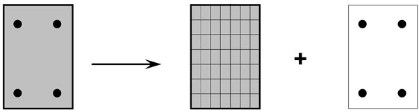
Figure 4. Fiber element hinge method.
method an RC section of a member was modeled as number of fiber elements. Each fiber follows stress-strain relation of its own material to the rupture point. After this stage, its capacity suddenly dropped to zero. This method continued until one of the tensile bars ruptured according to the experimental results. In this approach, the length of plastic hinges is assigned equal to the depth of members. The most prominent capability of this method is the consideration of axial-moment interaction for all members.
Theoretically, hinges can occur anywhere along the members. However, hinges are allowed to occur at the ends of each member. This simplifies the model by placing hinges in the most probable locations [6].
Regarding large displacements occur during progressive collapse, equilibrium equations for each step of analysis should be written for deformed configuration of structure. Thus, large displacements were considered by option of (P-Δ) plus large displacement in software. For this, members were divided in small lengths to consider the fundamental of small strains along a member. In this research, members were divided into maximum length of 10 cm.
Tables 1 and 2 summarize the details of the prototype and the model frame configuration.
4. Results and Discussion
Some of the most important experimental and analytical results were compared. Four effective criteria were assumed for the comparison purpose:
1) Horizontal displacement of frame column,
2) Reinforcing bar strain response at beam ends on first floor,
3) Rupture of reinforcing bar in beam,
4) Stages of the collapse.
4.1. Horizontal Displacement of Frame Column
The relationship between the horizontal displacement of the first-floor frame column, as a representative for other columns, and unloading displacement of the middle column are shown in Figure 5 for experimental results of Yi [24] and analytical models of this research.
In accordance with Figure 5, which is scaled in mm, it can be inferred that model based on FEH has almost an acceptable compatibility with experimental results. Results showed 80% verification for FEH. On the other hand, model based on FEMA 356 demonstrated considerable differences with respect to the experimental data. In fact, obtained horizontal displacements for FEMA 356 plastic hinges are at least twice the experimental results. Moreover, the compatibility of the shape of curves with experimental data should be considered carefully.
As shown in the curve of experimental results, in small vertical unloading displacements (5 - 150 mm) the adjacent columns of the removed (middle) column moved
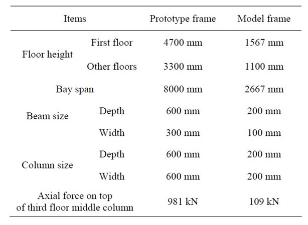
Table 1. Basic configuration of prototype and model frame [24].
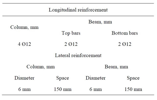
Table 2. Beam and column reinforcement [24].
away from each other. At the unloading displacement of 150 mm, due to the formation of catenary action, columns moved toward the middle column. This important behavior, which is the specific behavior of progressive collapse resulting from the large displacements, was obvious in the curve of FEH. Thus, the model of FEH had an acceptable compatibility with experimental and actual behavior of the structures during collapse. In contrast, not only was not FEMA 356 hinge model for material nonlinearity able to capture the onset of behaviors such as catenary action, and negative horizontal displacements at the beginning of the analysis, but also, demonstrated large data for horizontal displacements.
4.2. Reinforcing Bar Strain Response at Beam Ends on First Floor
Figure 6 shows the relationship between the reinforcing bar strains at the beam ends and the displacement of the middle column for experimental and FEH model. Model of based on FEMA 356 lacked such capability, since its nonlinear behavior is idealized by Figure 3. As illustrated in Figure 6, compatibility of 100% for FEH model in tensile bar (1-1) with the experimental results is clear for the range of 0 - 25 mm. According the experimental results, tensile reinforcing bar (1-1) yields in 25 mm
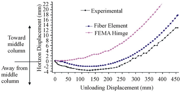
Figure 5. Effect of downward displacement of middle column on horizontal displacement of columns at first floor level for experimental and analytical models.

Figure 6. Reinforcing bar strain response at beam ends on first floor for experimental data of Yi [24] and analytical model of the same frame with FEH.
[24]. This fact is obvious in FEH model by sudden increase of strain. However, the experimental results do not obey this fact and there is no mentioned reason for a constant strain in the range of 25 - 50 mm for tensile bar by the Yi [24].
The comparison results of compressive bar (1-2) demonstrated 100% compatibility between analytical and experimental results until the unloading displacement of 150 mm. The catenary action causes compressive strain to convert to tensile strain. This phenomenon is apparent for FEH in Figure 6. In fact, FEH model is correctly following the same process as the experimental results do.
The observed differences between the experimental and analytical results are unavoidable, since the simplified assumptions such as isotropic material, and stressstrain idealizations are common in modeling.
4.3. Rupture of Reinforcing Bar in Beam
The step by step relationship of tensile-bar strain and unloading displacement of first floor beam adjacent to the middle column was plotted in Figure 7 for the FEH model. The picture of bar rupture at the end of experimental analysis is shown as well.
The results of FEH model showed the rupture at the unloading displacement of 450.2 mm for the tensile bar at the end of analysis. The comparison demonstrated the compatible results of rupture for analytical model with experimental results (the rupture strain of 0.12 for reinforcing bar) at the corresponding unloading displacement. Same as the Figure 6, there is no measurable data for strain of model based on the FEMA 356.
According to the experimental results, there are some important stages during progressive collapse. Some of them such as catenary action, formation of tensile forces in beams, and interaction of axial forces with bending
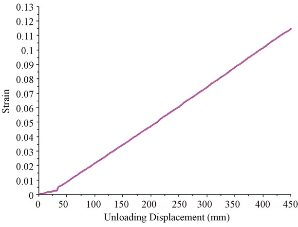
Figure 7. Rupture of reinforcing bar in beam for the analytical results of FEH model.
moment in beams are special characteristics of progressive collapse. The final stage of model frame based on the FEMA 356 hinges, which is shown in Figure 8, reached as the bending capability of the concentrated plastic hinges dropped to Zero. Red spots illustrate the final capacity of plastic hinges formed in beams. After this point any additional displacement made the entire model unstable and analysis process stopped without depicting the formation of catenary action, i.e., this method showed an untimely collapse for the frame that did not satisfy the research objectives simulating actual stages of collapse.
The other capability of FEH, as discussed before, is the consideration of axial-moment interaction for all members. This method is a proper method specially for beams during Catenary action. Catenary action is considered as the resistant action of beams to avoid large displacements. During catenary action, tensile forces form in beams according to the experimental results [3,24]. Figure 9 provides a schematic formation of tensile forces during catenary action. Analytical results of FEH model, which is plotted in Figure 10, proved the formation of tensile force in beams with the onset of catenary action in the unloading displacement of 140 mm as well.
So, the presence of tensile forces in beams caused an unavoidable interaction between the bending-moment stress and tensile-force stress which affected the RC section of beams. This is obvious in Figure 6, by conversion of compressive strain to the tensile strain. However, model based on the FEMA 356 hinges did not have the capability of considering such interaction in beam elements to provide more accurate consequences. FEH model considered such interaction not only for the col-
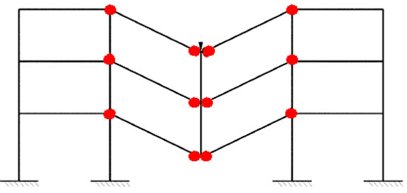
Figure 8. Final stage of analytical model based on the FEMA356 hinges (Plastic mechanism) [24].
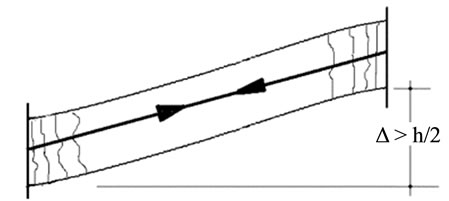
Figure 9. Formation of tensile forces in beams due to catenary action.
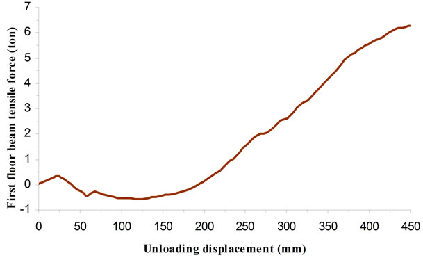
Figure 10. Formation of tensile forces in the first floor beam, removed-column span, by the increase of unloading displacement of FEH model.
umns but also, for the beams encountering catenary action.
5. Conclusion
Heavy impact loads due to tsunami against building can be one of the scenarios of progressive collapse during tsunami disaster. Since progressive collapse includes material and geometry nonlinearity during collapse propagation. This research investigated the proper model for material nonlinearity of members during progressive collapse due to the impact loads of tsunami disaster. This claim was investigated in this paper. For this purpose, one of the recent experimental results on system-level progressive collapse of an RC frame was used as a reference and verification of analytical data. The results of two analytical models were compared with the experimental results. One of them was common and simplified Idealized Component Load-Deformation curve based on the FEMA 356, and the other was FEH method. Material nonlinearity models, which were able to demonstrate the specifics of progressive collapse such as catenary action, axial-moment (P-M) interaction of beams during catenary action, and reflecting the stages of progressive collapse, considered as proper model for progressive collapse analysis. Regarding the experimental data the rupture of the reinforcing steel bars in the floor beams ultimately controlled the analytical results. Comparison curves demonstrated the predominating capability of FEH method in verifying the experimental results. In addition, FEH method was able to consider the P-M interaction in beam elements due to the catenary action and tensile forces in beams. In contrast, FEMA 356 hinges were so conservative in comparison with the experimental data, and were not able to provide some comparable results such as strain response details. Moreover, this method caused a precocious collapse that cannot simulate the resistant capabilities of structure during catenary action. Indeed, FEMA 356 method for material nonlinearity can offer a preliminary evaluation for a structure but the results are not so reliable for research or practical purposes. However, FEH method was neither sophisticated for research and/or practical purposes, nor unreliable. This method can be used as one of the proper equivalents for material nonlinearities especially for progressive collapse analysis.
REFERENCES
- J. J. Wijetunge, “Tsunami on 26 December 2004: Spatial Distribution of Tsunami Height and the Extent of Inundation in Sri Lanka,” Science of Tsunami Hazards, Vol. 24, No. 3, 2006, pp. 115-133,225-239.
- L. Lytton, “Deep Impact: Why Post-Tsunami Wells Need a Measured Approach,” Proceedings of ICE, Civil Engineering, Vol. 161, No. 1, 2008, pp. 42-48.
- M. Sasani and J. Kropelnicki, “Progressive Collapse Analysis of an RC Structure,” The Structural Design of Tall and Special Buildings, 2007. www.Interscience.wiley.com
- H. J. Choi and T. Krauthammer, “Investigation of Progressive Collapse Phenomena in a Multistory Building,” Protective Technology Center, The Pennsylvania State University, 2003.
- NIST, “Best Practices for Reducing the Potential for Progressive Collapse in Buildings,” National Institute of Standards and Technology Report No. NISTIR 7396, USA, 2007.
- DoD, “Design of Building to Resist Progressive Collapse,” UFC 4-023-03, Unified Facility Criteria, US Department of Defense, Washington DC, 2005.
- ASCE/SEI 7, “Minimum Design Loads for Buildings and Other Structures,” Structural Engineering Institute, American Society of Civil Engineers Reston, VA, 2005.
- E. A. Bryant, “Tsunami; The Underrated Hazard,” Cambridge University Press, Cambridge, 2001.
- M. S. Kirkgöz, “An Experimental Investigation of a Vertical Wall Response to Breaking Wave Impact,” Ocean Engineering Journal, Vol. 17, No. 4, 1990, pp. 379-391. doi:10.1016/0029-8018(90)90030-A
- M. S. Kirkgöz, “Influence of Water Depth on the Breaking Wave Impact on Vertical and Sloping Wall,” Coastal Engineering Journal, Vol. 18, No. 3-4, 1992, pp. 297- 314. doi:10.1016/0378-3839(92)90025-P
- E. S. Chan, “Mechanics of Deep Water Plunging Wave Impacts on Vertical Structures,” Coastal Engineering Journal, Vol. 22, 1994, pp. 115-133.
- M. Hattori, A. Arami and T. Yui, “Wave Impact Pressures on Vertical Walls under Breaking Waves of Various Types,” Coastal Engineering Journal, Vol. 22, No. 1-2, 1994, pp. 79-114. doi:10.1016/0378-3839(94)90049-3
- M. S. Kirkgöz, “Breaking Wave Impact on Vertical and Sloping Coastal Structures,” Ocean Engineering Journal, Vol. 22, No. 1, 1995, pp. 35-48. doi:10.1016/0029-8018(93)E0006-E
- W. P. S. Dias, L. Fernando, S. Wathurapatha and Y. de Silva, “Structural Resistance against Sliding, Overturning and Scouring Caused by Tsunamis,” International Symposium, Disaster Reduction on Coasts, Scientific Sustainable Holistic Accessible, Monash University, Melbourne, 14-16 November 2005.
- A. Ghobarah, M. Saatcioglu and I. Nistor, “The Impact of the 26 December 2004 Earthquake and Tsunami on Structures and Infrastructure,” Engineering Structures Journal, Vol. 28, No. 2, 2006, pp. 312-326. doi:10.1016/j.engstruct.2005.09.028
- T. Okada, T. Sagano, T. Ishikawa, T. Ohgi, S. Takai and C. Hamabe, “Structural Design Method of Building for Tsunami Resistance,” Building Technology Research Institute, The Building Centre of Japan, Tokyo, 2004.
- US Army Corps of Engineers, “Wave Forces on a Wall Shoreward of the Still Water Level,” Coastal Engineering Research Centre, Vicksburg, Technical Note III-29, 1990.
- R. H. Cross, “Tsunami Surge Forces,” Journal of Waterways and Harbors Division, Vol. 93, No. 4, 1976, pp. 201-231.
- F. E. Camfield, “Wave Forces on Wall,” Journal of Waterways, Ports, Coastal and Ocean Engineering, Vol. 117, No. 1, 1991, pp. 76-79. doi:10.1061/(ASCE)0733-950X(1991)117:1(76)
- Federal Emergency Management Agency, “Coastal Construction Manual,” FEMA, Washington DC, 2003.
- W. P. S. Dias and H. M. Y. C. Mallikarachchi, “Tsunami—Planning and Design for Disaster Mitigation,” The Structural Engineer, Vol. 84, No. 11, 2006, pp. 25-29.
- H. Yeh, I. Robertson and J. Preuss, “Development of Design Guidelines for Structures that Serve as Tsunami Vertical Evacuation Sites,” Washington Division of Geology and Earth Resources, Washington State Department of Natural Resources, Olympia, 2005.
- S. Nakamura, “Shock Pressure of Tsunami Surge on a Wall, International Union of Geodesy and Geophysics,” Tsunami Committee Meeting and Symposium, Wellington, UNESCO Press, Paris, 1976, pp. 177-185.
- W. J. Yi, et al., “Experimental Study on Progressive Collapse-Resistant Behavior of Reinforced Concrete Frame Structures,” ACI Structural Journal, Vol. 105, No. 4, 2008, pp. 433-439.
- FEMA 356, “Prestandard and Commentary for the Seismic Rehabilitation of Buildings,” Federal Emergency Management Agency, Washington DC, 2000.
- J. Kim and T. Kim, “Assessment of Progressive CollapseResisting Capacity of Steel Moment Frames,” Journal Constructional Steel Research, 2008.
- M. Sasani, M. Bazan and S. Sagiroglu, “Experimental and Analytical Progressive Collapse Evaluation of an Actual Reinforced Concrete Structure,” ACI Structural Journal, Vol. 104, No. 6, 2007, pp. 731-739.
- S. M. Marjinishvili, “Progressive Analysis Procedure for Progressive Collapse, Performance of Constructed Facilities,” Journal of Performance of Constructed Facilities, Vol. 18, No. 2, 2004, pp. 79-85.