Open Journal of Civil Engineering
Vol. 2 No. 3 (2012) , Article ID: 22989 , 15 pages DOI:10.4236/ojce.2012.23019
Performance of a Panelized Brick Veneer Wall System under Lateral Loads
1Thornton-Tomasetti Inc., New York, USA
2Department of Architectural Engineering, The Pennsylvania State University, Pennsylvania, USA
Email: jianhailiang@thornntontomasetti.com, amm7@psu.edu
Received May 17, 2012; revised June 18, 2012; accepted June 30, 2012
Keywords: Brick Veneer; Steel Stud; Lateral Loads; Panelized Building Envelope; Wind Load Test; Racking Test
ABSTRACT
This paper discusses the performance of a proposed panelized brick veneer over steel stud backup wall system and seismic isolation connections under lateral loads. The panelized wall system was developed to address some shortcomings of the conventional brick veneer wall type. The details of the system are briefly introduced. The study evaluated the performance of the system under out-of-plane simulated wind loads and in-plane cyclic loads using full-scale laboratory experiments. The test setup, test specimen, test procedure, and test results are presented and the performance of the system is evaluated accordingly.
1. Introduction
Brick veneer over light gauge steel stud backup walls (BV/SS) was introduced in the 1960’s [1]. Compared with concrete masonry unit (CMU) backup walls, one important advantage of steel stud (SS) framing is that it is much lighter than CMU wall system, which makes SS framing relatively easier to handle during construction. Furthermore, with the reduced weight of the building exterior walls, the building structure can be designed for much less gravity and earthquake induced loads.
However, the BV/SS walls are also known to have experienced serviceability damage to brick veneer (BV), including cracking under high wind loads, wind driven rain penetration, and tie corrosion [2-7]. This is mainly due to the mismatch of stiffness and strength between the BV and the SS. Unlike CMU backup, SS is relatively flexible and under high wind loads it tends to develop large deflections if unrestrained over the height. However, since the BV is connected to the SS through masonry ties and is relatively stiff, it will initially resist all the out-of-plane lateral loads, and only as the BV deflects considerably, does the SS start to participate in lateral load resistance. Eventually, once the BV forms a through-thickness bed joint crack and loses its stiffness, the lateral load will be primarily resisted by the SS. The cracked BV easily allows rain to penetrate through the BV and reach its interior surface, and this is normally identified as a major cause of some moisture related problems. Besides the serviceability issues associated with water leakage behind the BV that would require repair, in some cases the parties involved may have to deal with litigation problems as well. Furthermore, the side issue of corroded ties can be an even more serious concern during earthquakes.
Conventional BV over CMU backup walls (BV/CM) and BV/SS walls have gaps under shelf angles as shown in Figure 1. These gaps serve as horizontal movement joints and are supposed to prevent BV from participating in in-plane load resistance. However, in practice the gap is sometimes filled with mortar instead of deformable sealant and can lead to participation of the BV in lateral in-plane load resistance and subsequent damage [8]. Another reason for the closure of gaps is attributed to differential movement between the BV and the backup. This problem, along with the out-of-plane flexural cracking problem due to wind, has been a concern for the use of BV/SS system in some areas.
In order to address such problems associated with conventional BV/SS wall systems, the conceptual design of a multi-hazard resistant panelized brick veneer over steel frame backup wall system (PBVSS) has been developed at Penn State University. The design includes the concept of panelization, use of rolled steel frame and SS backup, seismic isolation system, and many building-science related details [9]. Finite element analysis, full-scale wind load test, and full-scale seismic racking test were used to evaluate the performance of the proposed system. The building science aspect of the work [10] and some of wind loading aspects [11] have been discussed to some
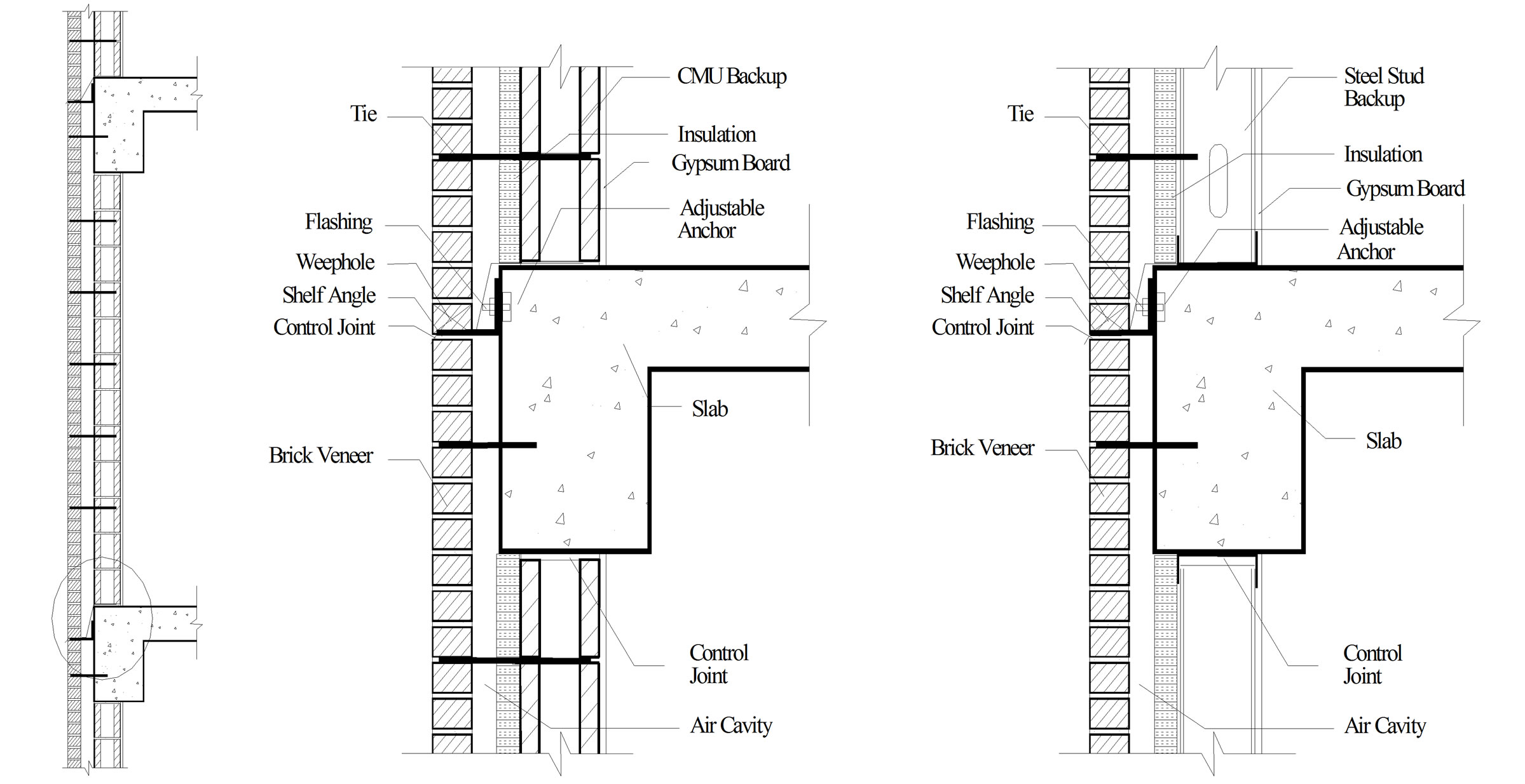
Figure 1. Typical sections of BV/SS and BV/CMU wall systems.
extent in two recent papers. The objective of this paper is presentation of the results of full-scale racking (seismic simulation) and more aspects of wind load tests on PBVSS specimens and evaluation of the proposed system under such in-plane and out-of-plane lateral loads.
2. Literature Review
As mentioned, the BV/SS wall system is sensitive to deflections under out-of-plane wind pressure. The BV wythe can crack under a 1.2 kN/m2 pressure and an overall BV deflection of only 1/2500 to 1/1800 of the wall height [12,13]. In order to decrease BV deflection, a) stiffer SS can be used as backup, b) stiffer ties and also more ties can be used at the top of the wall [14], or c) the end studs can be restrained to promote two-way bending mechanism in the wall panels [13]. Since water leakage is largely related to crack width (i.e., the wider the crack, the greater the leakage), stiffer SS as backup is also beneficial to the wall panel performance by minimizing the crack width.
Certainly, even if BV cracking under wind loading can be minimized, the BV will inevitably crack due to the mortar shrinkage and the effect of temperature or moisture content change on the wall components. Therefore, it is fundamental to the BV/SS design to have a drainage mechanism [15,16]. The wall can also be carefully engineered to promote the pressure moderation, which means decreasing the differential pressure between interior and exterior surfaces of the BV to minimize the driving force for water penetration [17].
Although it may be assumed that all ties will have the same force [18], normally the ties at the top will experience larger forces if ties are uniformly distributed [14, 19]. Therefore, it makes more sense to use more ties at the top portion of the walls to prevent tie buckling under high out-of-plane loads, and hence the wall panel failure can be more of a ductile nature [14].
Unlike load bearing masonry wall systems, very little research is available on seismic performance of masonry veneer walls. In the past, BV walls were not necessarily designed by structural engineers. Today, there is increasingly better awareness of the importance of the seismic design of masonry veneer walls. It is understood that although veneer wall cracking failure may not jeopardize building structural integrity, it can be costly to repair and the failure can also lead to life-safety hazards [20]. Structural engineers are now increasingly involved in the actual design or review and evaluation of the design for structural and/or waterproofing aspects. In particular, because of the seismic resistance requirements in building codes, the masonry veneer wall designs are required to be reviewed by structural engineers.
In typical BV with backup walls, the BV wythe is usually supported on shelf angles, while the backup wall is either supported on the slab or by the spandrel beam. The ties that connect the BV to the backup are normally designed in a way that they can only transfer forces perpendicular to the BV but are flexible in the plane of BV. At the same time, there are horizontal and vertical movement joints which are supposed to isolate in-plane movements of the backup wall from the BV. However, the movement joints can be decreased in size or even closed by differential movements between the BV and the backup wall because of thermal deformation, moisture deformation, elastic deformation under load, creep, etc. If horizontal movement joints are closed, large compressive stresses will build up between the BV and the shelf angle supporting it, which can cause brick veneer bowing and spalling. In case a movement joint is closed, the friction force between the BV and the flashing/shelf angle can transfer in-plane seismic forces from the main structure to the BV [8].
Various brick wall failure modes have been studied by Magenes and Calvi [21,22]. The brick wall strength, deformability and energy dissipation capacity under inplane seismic loads were evaluated with cyclic compression-shear test results and analytical data. The parameters that can influence the brick wall performance were identified to be geometry, boundary conditions, magnitude of compressive force, load rates, brick and mortar material property, and the interface condition between brick and mortar. The failure mechanisms were classified as rocking failure, shear cracking, and sliding.
Kelly et al. [15] studied the BV/SS performance under out-of-plane seismic loads using the finite element analysis. The analysis showed that after cracking, steel studs remained elastic if the ties and their connections to BV/SS did not fail. Computer analysis was also used to investigate out-of-plane performance of BV/CM walls under seismic loads with concentration on tie performance [23]. Both elastic and elastic/plastic analyses were performed.
In summary, literature review on behavior of conventional BV wall systems shows that there are many aspects of the system that still need research for better understanding of their behavior. There also seems to be many opportunities for innovations in this wall system category.
3. Introduction of the PBVSS System Design
The proposed PBVSS system is based on prefabricating the entire BV and SS backup wall as a panel. While the BV resembles that of a conventional BV/SS, the light gauge SS backup system is made to be much stiffer and more robust than conventional SS backup system in order to control the maximum SS deflection and thus the BV crack width. The SS backup takes advantage of a rolled steel frame made up of top and bottom built-up steel beams and two vertical channels on the sides. The bottom beam is made up of a channel supporting the SS and a steel angle supporting the BV. Therefore, the bottom beam serves the function of a shelf angle in conventional BV/SS. The top beam is made up of a steel channel and a steel plate. The steel channel can hold the top end of the SS and the steel plate extending all the way to the top end of the BV provides out-of-plane support for it. The two vertical channels on the ends can provide much higher out-of-plane restraint to the sides of the BV than SS used in conventional walls and can potentially help the system to develop two-way bending mechanism. The top beam, bottom beam, and vertical channels form a very stiff backup frame (Figure 2), which can also ease the wall panel transportation and erection. The SS backup is made up of 12 gauge studs spaced at 400 mm and used as intermediate vertical members. Two 12 gauge studs back-to-back are used at the center to prevent lateral torsional buckling.
The SS backup is connected to the BV with shear connectors (Figure 3). As opposed to conventional flexible adjustable ties that are anchored to SS flanges, stiffer shear connectors are used [24]. Because of their higher axial stiffness and strength, shear connectors can transfer out-of-plane loads from the BV wythe to the SS more efficiently. In addition, shear connectors are directly anchored to the SS web, hence provide more reliable connections and can prevent buckling of the studs flanges. Typical horizontal and vertical tie spacing used is 400 mm, which is the spacing of SS members, while smaller vertical tie spacing is used at the top of the wall to address the conventional non-uniform tie force distribution discussed previously.
The in-plane performance of conventional BV wall systems can be complicated because the SS backup wall is supported directly by the floor slab, while the BV is supported on a shelf angle. In cases where the horizontal movement joint under the shelf angle is closed by mortar or vertical thermal and moisture expansion of the brickwork, the BV can actually experience in-plane vertical compression. Therefore, instead of solely relying on the horizontal joints, a seismic isolation system is introduced
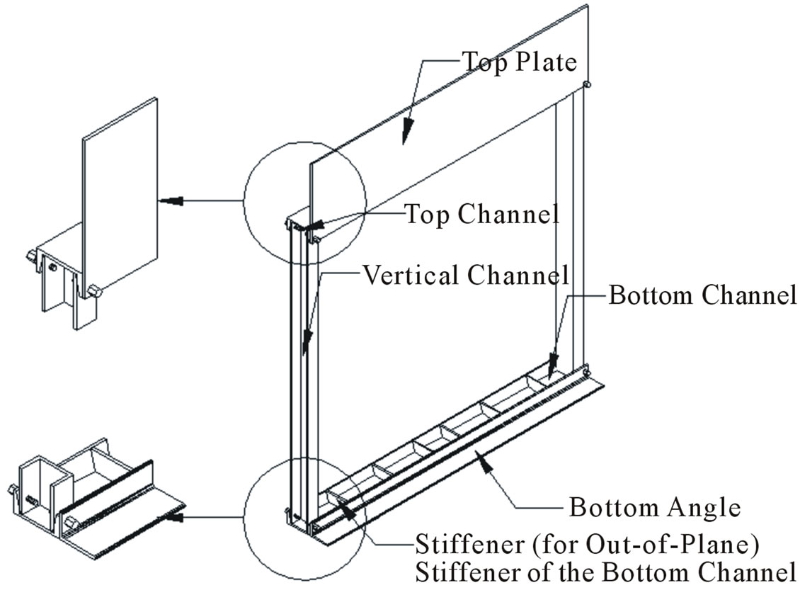
Figure 2. Isometric view of the steel support frame.
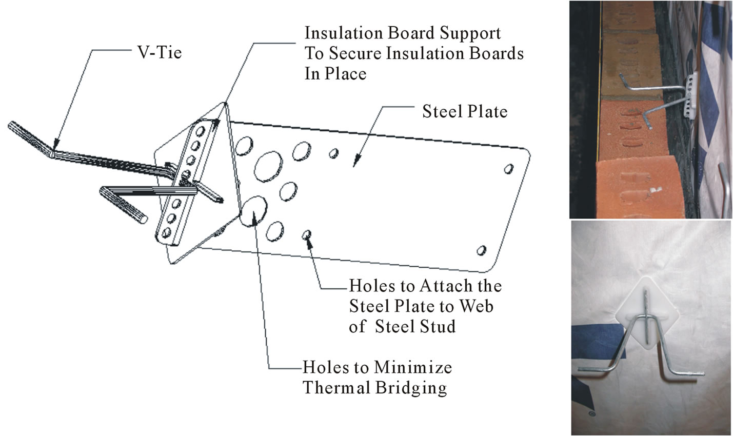
Figure 3. Shear connector [24].
in the proposed PBVSS system to allow in-plane panel movement with respect to the main structure system. The connection of the proposed prefabricated panel to the structure can be through bearing and lateral (tie-back) connections as a swaying system or through slotted hole connections for rocking response to lateral interstory drift, as is common in precast concrete panels [25]. The former is the conventional type connection used in the United States and is the type used in the proposed PBVSS system as shown in Figure 4. The bearing connection consists of placing the bottom channel over the floor slab through threaded rods embedded in the slab. The lateral (tie-back) connection consists of rods attached to the floor system as shown in Figure 4. Those threaded rods at three points can restrain out-of-plane movement of the panels. In case of in-plane movements, however, the rods will bend and allow the wall panel to move with the supporting slab. These lateral connections can be used on the vertical members of the support steel frame or the top channel as construction details allow.
Because the BV may experience some cracking, although not likely due to lateral loads, and some rain may leak to the interior side, an air cavity with drainage is included in the design for water that may penetrate through the BV or form by condensation. Conventional features of BV/SS walls such as thermal insulation, vapor retarder, air barrier, air cavity, vents, weep holes and sheathings are designed and included in PBVSS to improve performance of the system regarding buildingscience related problems such as excessive heat exchange, condensation, water leakage, and air leakage. The design can also potentially help to achieve pressure equalization/moderation.
4. Experimental Program
The experimental program consisted of air pressure loading of full-scale specimens to simulate wind loading

Figure 4. PBVSS elevation.
and subjecting the specimen to racking displacements to evaluate seismic performance.
4.1. Wind Loading Test Setup and Loading Protocol
The major objectives of the wind load tests were to: 1) study the performance of wall panels under cyclic out-ofplane loading, with specific concentration on BV cracking and water leakage through the cracks; 2) provide data for potential improvement of the current PBVSS design with respect to the performance under out-of-plane loading; and 3) provide data for comparison with finite element analysis results and to evaluate efficiency of the computer model [26]. Two specimens, one conventional BV/SS and one proposed PBVSS system were tested. The specimens were tested under simulated out-of-plane wind load on the Wind Load Test Facility (WLTF) in the Building Envelope Research Laboratory (BERL) at Penn State University. A wood chamber as shown in Figure 5 was built to enclose all edges of the specimens except the bottom edge, where the specimens were supported by a concrete slab to create floor slab or spandrel beam supported condition. Cyclic air under positive (wind blowing against the exterior face of the BV) or negative (wind sucking from the exterior surface of the BV) pressure at ambient conditions were generated by three 1.90 m3 accumulators, controlled manually by valves, and supplied to the chamber through a manifold located at the center of the test frame. The test procedure generally followed the ASTM E1233-00 [27].
The load spectrum used for wind load was based on the “Other Extreme Wind Test Spectrum” specified in Table X1.2 of ASTM 1233-00. However, in order to cut down the total number of cycles in the tests, the positive and negative cycles were applied only once instead of seven times as specified in the standard spectrum. Moreover, due to the difficulty in achieving high negative pressure, the negative steps were just repeated once instead of four times as specified by ASTM standard. The cut-down was also based on the consideration that repeating the cycles more than once would not have any substantial effect on the performance of specimens. The duration of each air pressure cycle was 5 seconds. Service wind pressure was calculated to be 1 kN/m2 based on ASCE 7-10 [28] assuming an exposure category C and a basic wind speed of 145 km/h. Cyclic wind load tests were repeated with 1 kN/m2 increments in the maximum pressure between steps until the specimen failed or the capacity of the test facility reached. After the first wind loading cycle, the last cycle and some other intermediate cycles that were considered important, water penetration tests were also carried out to study the influence of cyclic wind load on the amount of water leakage through the BV. Water leakage tests followed the ASTM E514-03C [29].
Pressure on the exterior and interior (within the air cavity) sides of the BV were measured during the tests to monitor the wind pressure applied. Out-of-plane deflecttions of the BV and the steel backup were measured using linear variable differential transformer (LVDT) to compare the out-of-plane performance and the extent of composite behavior between the conventional and PBVSS wall panels. All LVDTs were mounted on a separate supporting frame to isolate the sensors from test specimen movements. Tie forces were also measured to evaluate the level of tie forces under out-of-plane loads and to study the tie force distribution. Tie force measurements were taken indirectly by measuring strain in the ties that yielded tie force distribution in both horizontal and vertical directions. Due to factors such as cutouts on shear connector ties, surface unevenness, and misalignment, the strain-force relationship was expected to deviate from idealized Hooke’s Law. Therefore, before attaching ties to vertical members (studs), the strain gauges were calibrated individually to establish the relationship between strain readings and tie forces.
4.2. Racking Test Setup and Loading Protocol
After the wind load tests, the PBVSS specimen was
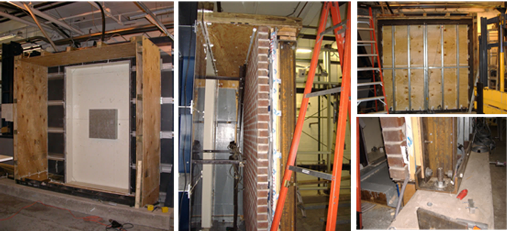
Figure 5. Wind loading test setup.
moved to the Dynamic Racking Test Facility (DRTF) in the BERL for the in-plane racking test. In order to prevent any damage to BV on actual buildings during earthquakes, the wall detail should allow for seismic isolation of the BV wall system from deformations of the primary structural system. Therefore, objectives of the racking load testing reported here were as follows: 1) to understand the behavior and efficiency of tie-back connections used in the panelized wall design to isolate the walls from in-plane seismic movement; 2) to determine the drift limit of the system; 3) to investigate the wall panel behavior under in-plane cyclic load (cracking development, stiffness and strength degradation, energy dissipation, failure mode, etc); and 4) to investigate the influence of the tie-back rods cross sectional area on the connection behavior. Both 13 mm and 10 mm diameter tie-back rods were tested for comparison.
The test facility shown in Figure 6 is made up of two sliding steel tube beams and two steel tube columns with two steel threaded rods providing diagonal bracing. The columns are fixed at the bottom and the beams are supported by the columns with brackets. A hydraulic actuator ram controlled by an electrohydraulic servovalve and connected to the bottom beam pushes the beam in the horizontal direction. The actuator ram is supported by a separate reaction frame. The maximum drift capacity of the bottom beam is ±76 mm. Magenes and Calvi [21,22] recommended 1% drift limit for in-plane movement of the brick wall alone, and the building code used, ASCE 7 - 10 [28], called for a 2% story drift, which is equivalent to about 48mm for this specific specimen. However, a higher drift ratio had to be tested to investigate the ultimate drift ratio capacity of the system. Therefore, a fulcrum assembly and a pivot arm were used on the racking test facility to couple the top and bottom beam. The mid-point of the pivot arm was attached to the mid-point of the column so that when the bottom beam was moved by the hydraulic ram, the top beam would be moved with the same amount in the opposite direction. As a result, the drift capacity of the facility with the fulcrum assembly was doubled to ±152 mm. At the same time, however, the maximum frequency at higher drifts had to be de-
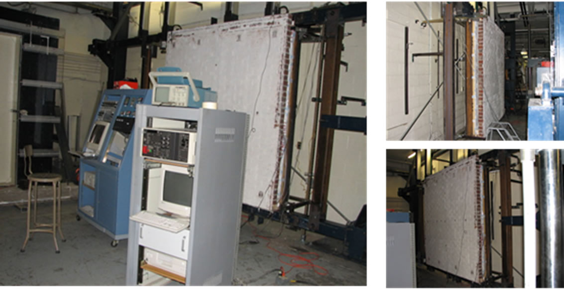
Figure 6. Racking test load facility (DRTF).
creased because of the system capacity limitation. Since this test did not intend to simulate a real earthquake, the frequency was not a major concern. The main objectives of the experimental racking study were to investigate the performance of the tie-back connections, the BV, as well as determining the drift capacity of the system under cyclic racking displacements as a means to develop an understanding of the behavior of the wall under earthquake induced movement. Displacement controlled cyclic racking history (Figure 7) developed originally for curtain walls were used as input for this test [30]. To facilitate the data acquisition and observation of the specimen during the test, the whole racking history was divided into shorter segments [31]. Each segment started with 10 cycles of ±2 mm displacement. Then for each step, the displacement amplitude was increased to the peak value in four cycles, kept constant for five cycles, then returned to zero in four cycles, as shown in Figure 7(a). In order to determine the drift limit of the PBVSS wall system, the maximum stroke of the loading facility was used. The maximum magnitude of drift in each step started from 6 mm and increased by 6 mm in each step up to 152 mm or until the specimen failed. Therefore, there would be 24 steps in the test if the specimen did not fail during the test. The frequency of the accelerogram was 0.4 HZ or 0.8 HZ depending on the magnitude of movement. Figure 7(b) shows the complete loading history used.
The actuator had a built-in LVDT and load cell to measure the input displacement and load respectively. At each corner of the BV, one LVDT was attached on the side of the BV (on the vertical centerline) to measure the
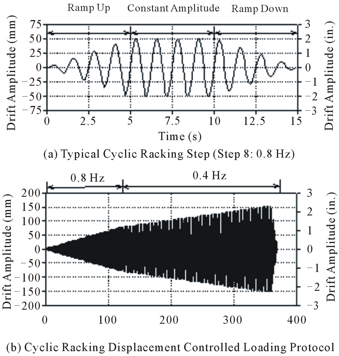
Figure 7. Drift time history for cyclic racking test. (Note: each racking step consists of ramp up, constant amplitude and ramp down cycles).
in-plane movement of the corners. There was also one LVDT on each top corner of the steel frame located at the same elevation as sensors on top corners of the BV. Besides LVDTs on the main body of the specimen, there was also one LVDT on each tie-back connection. Although the test was an in-plane racking test and the specimen was expected to move in-plane only without any vertical or out-of-plane movement, some measurements were also taken in these two directions to verify this assumption. Figure 8 schematically shows locations of all measurement points as well as photographs of some of LVDT attachments. The measurement sample rate was 100 samples per second, and each ten consecutive values were averaged to smooth out noises. At the same time, the load and displacement measured by the built-in load cell and LVDT were also shown on an oscilloscope to facilitate real-time control of the tests.
5. Description of Test Specimens
As is conventional in many wall component testing according to ASTM E72 [32] and ASTM E564 [33], the dimensions of the BV specimen in this study were 2438 mm wide by 2438 mm tall, while the nominal thickness of the BV was 100 mm. The BV in the PBVSS specimen was supported by a bottom angle, which was connected to the bottom channel of the rolled steel framing. Short steel plates at the bottom and segments of light gauge SS at the top functioning as shear keys were used as out-of-plane restraints. The backup frame for the specimen consisted of seven vertical members spaced at 406 mm on center, as shown in Figure 9. The two end members were made with MC150 × 26.8 structure channels, the center member consisted of two 12 gauge SS back to back, and the remaining four members were single 12 gauge SS. The MC200 × 29.8 top and bottom channels were connected to the vertical channels with bolts. Stiffeners were welded to the bottom steel channel to increase its out-of-plane stiffness. Lateral supports were provided to the vertical members at mid height by continuous light gauge steel studs attached to both surfaces of the mem bers. The BV was connected to the SS backup with shear connectors with horizontal spacing of 406 mm. The vertical spacing of the connectors was generally 406 mm with closer spaced connectors at the top of the wall.
For ventilation of the walls, weep holes and vents spaced at 609 mm were constructed by leaving head joints open. The original weep holes and vents in the proposed PBVSS design were located at the top (vents) and bottom (weep holes) course. In order to accommodate the water collection system, weep holes in the test specimens were located at the third lowest course. Similarly, vents were located four courses from the top to
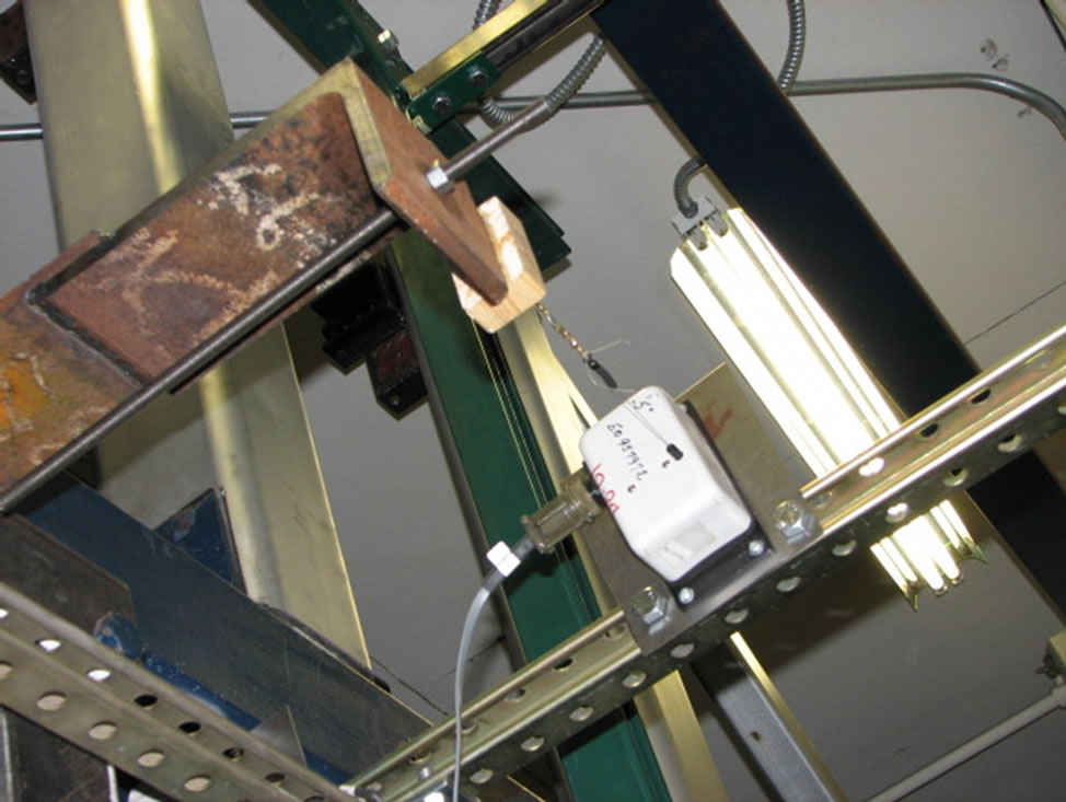
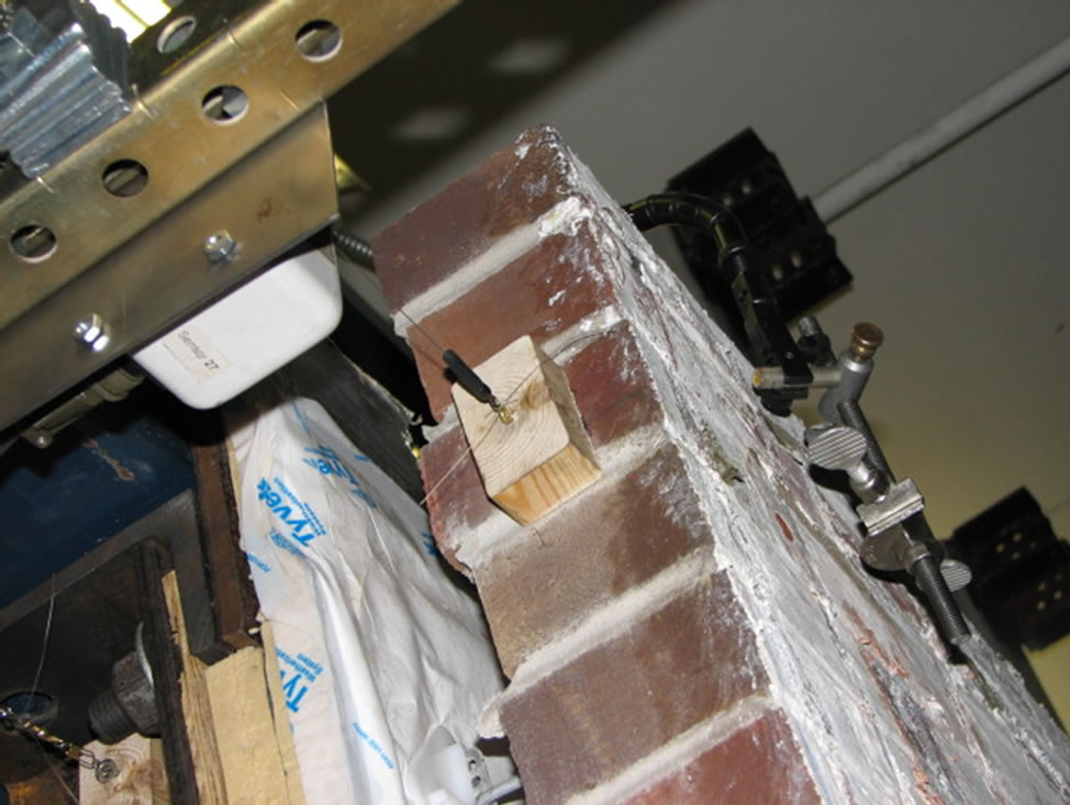
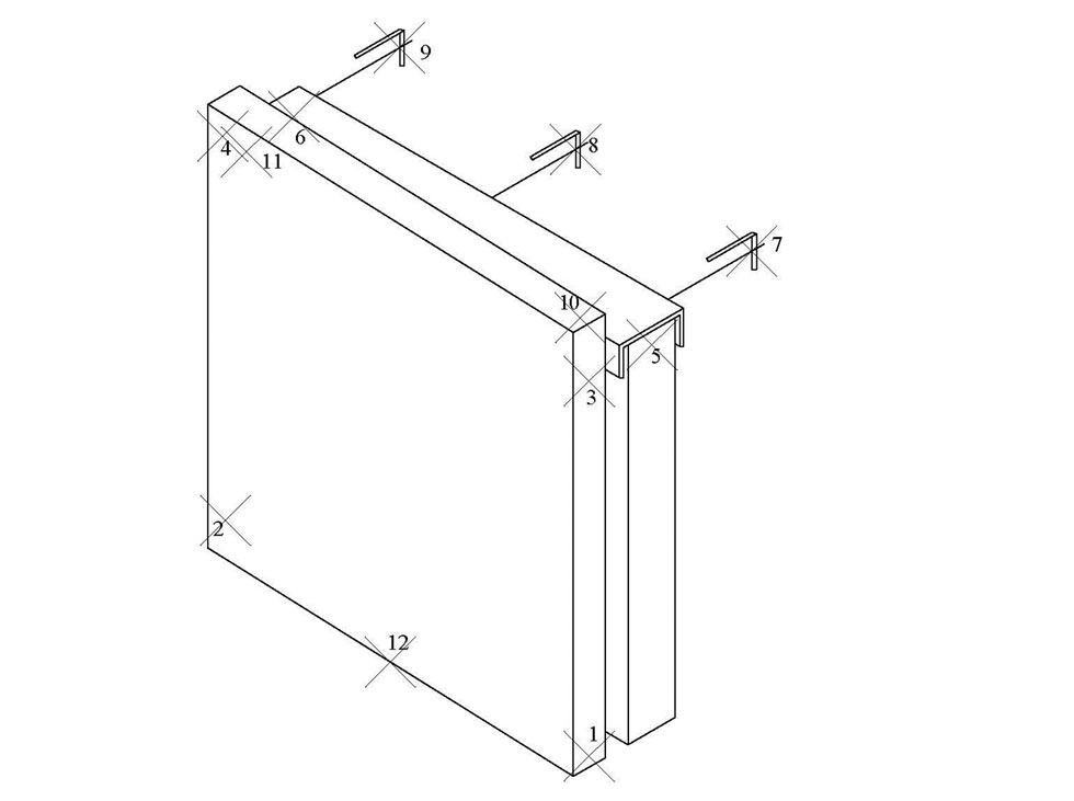
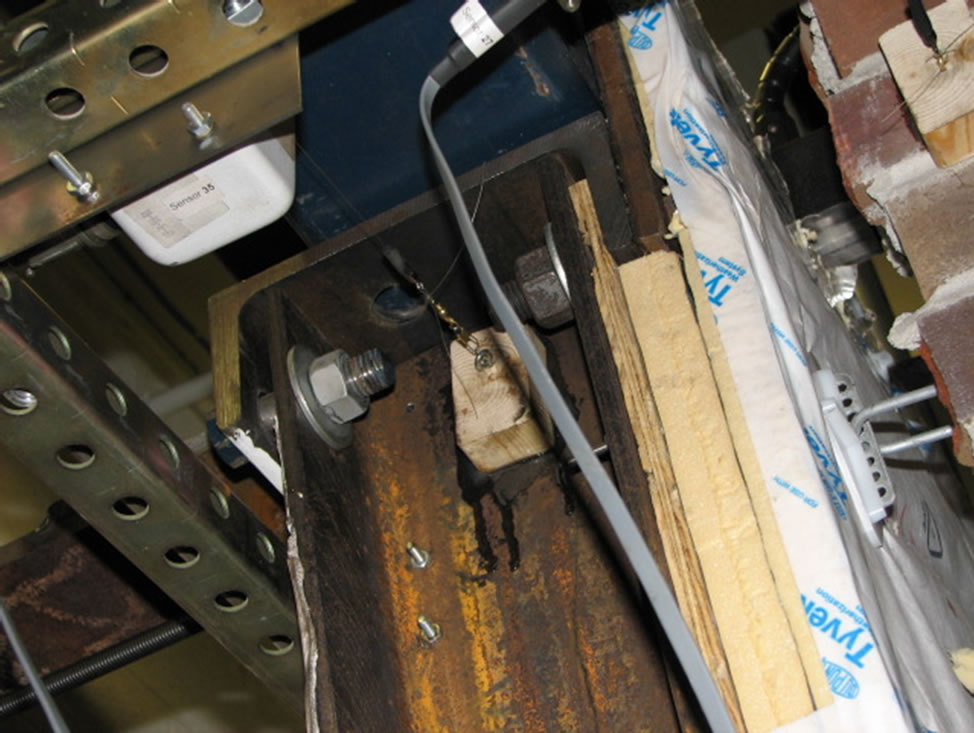
Figure 8. Example photographs and schematic locations of sensors for seismic test.
accommodate the water supply system. This modification was not expected to affect the test results since weep holes were included in the specimens for ventilation only rather than water drainage. Besides the BV and the SS backup, all other functional components used in typical BV/SS wall constructions were also included in the specimens. From exterior to interior, the wall section (Figure 9) consisted of the BV, 38 mm air cavity, Tyvek Housewrap, two layers of 25 mm thick Super Tuff thermal insulation board, 12 mm thick plywood board, SS backup, and 10 mm thick gypsum board.
The backup frame of the conventional specimen used seven 18 gauge SS. The studs sat on the web of the bottom track at the bottom and were connected to flanges of the top track with a 13 mm movement joint. The backup frame was connected to the BV with conventional DW-10 ties [34] as normally used in construction. The BV was supported by an L102 mm × 102 mm × 12.7 mm shelf angle, which was anchored to the reinforced concrete floor slab with J-hook anchor bolts. All other details of the conventional specimen including tie spacing, stud spacing and building science related features were the same as the PBVSS specimen.
Figure 6 shows photographs of the PBVSS specimen mounted on the DRTF. Boundary conditions of the test specimen simulated the actual construction. The bottom of the specimen as shown in Figure 10 was attached to the bottom spandrel beam of the test facility using three threaded rods. Locations of attachments were at the bottom corners and middle of the specimen. Similarly, L203 × 102 × 12.7 steel angles were welded to the side of the top spandrel beam next to the top corners and middle of the specimen. Then a L203 102 × 12.7 angle was welded to the long leg of each angle. The specimen was then connected to these angles through 432 m long 13 mm diameter threaded rods, as shown in Figure 11. These connections were designed to provide out-of-plane lateral supports (i.e. axial force in the threaded rods). Figure 12 shows details of the top connection, while a vertical section of the entire test specimen is shown in Figure 13.
6. Discussion of the Simulated Wind Load Test Results
The conventional specimen was first tested under simulated wind load followed by water penetration test. Then the PBVSS was tested following a similar procedure. Figure 14 compares the deflection of BV components of the two specimens under the maximum air pressure of 6.0 kN/m2 along the height of the specimens. The figure shows that the maximum (mid-height) deflection of the conventional BV (7.97 mm) is approximately six times the maximum deflection of the PBVSS specimen (1.34 mm). Figure 15 compares tie forces versus pressure for the two specimens. Data shown are for the second tie from the top on the BV centerline. The relationship between tie forces and the pressure applied was generally linear for the conventional specimen, with some nonlinear portion at higher pressure levels. The maximum force
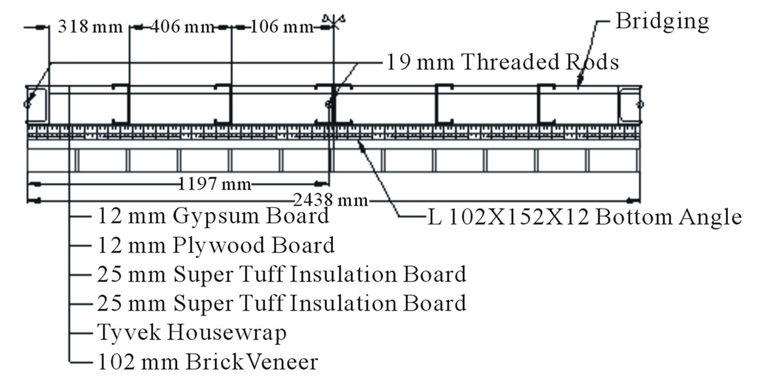
Figure 9. Horizontal section of the test specimen.
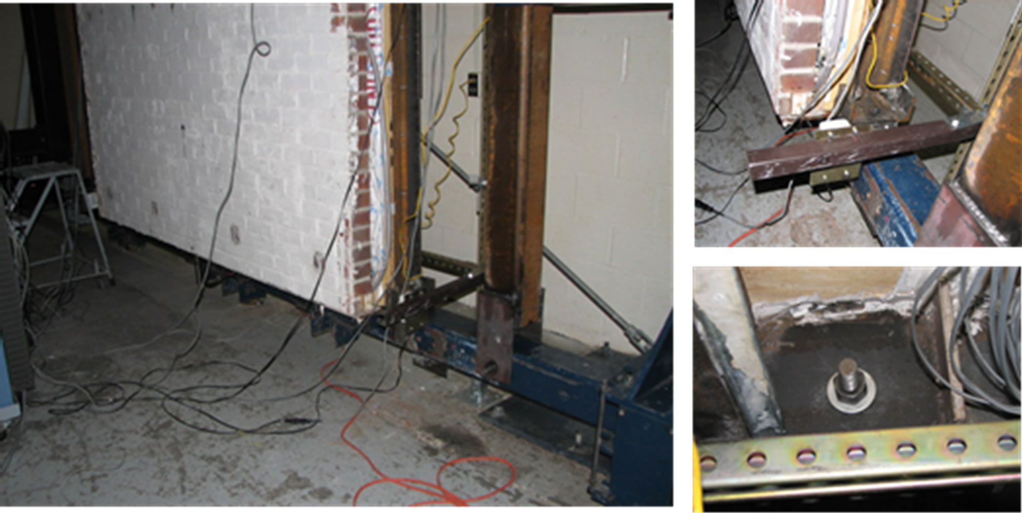
Figure 10. Attachment of the bottom channel to the lower spandrel beam of DRTF.
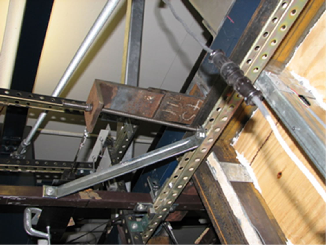
Figure 11. Attachment of threaded rod to the top spandrel beam of DRTF.
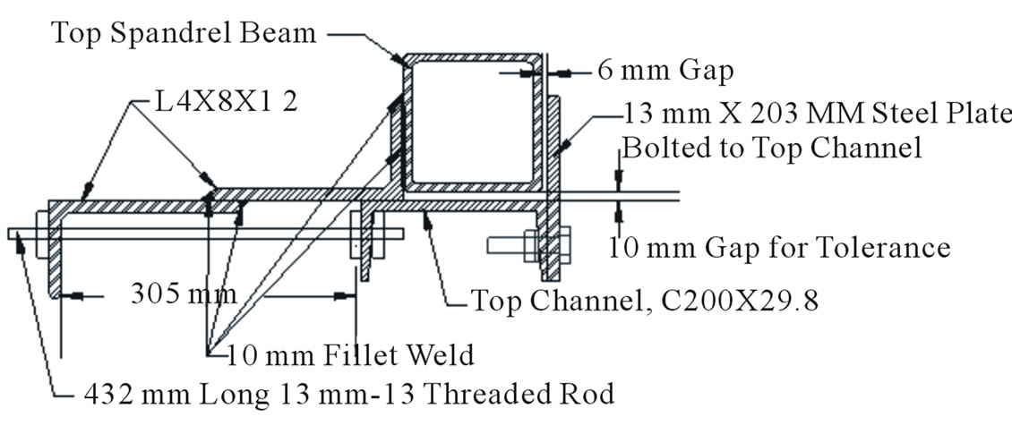
Figure 12. Details of seismic isolation connections at the top.
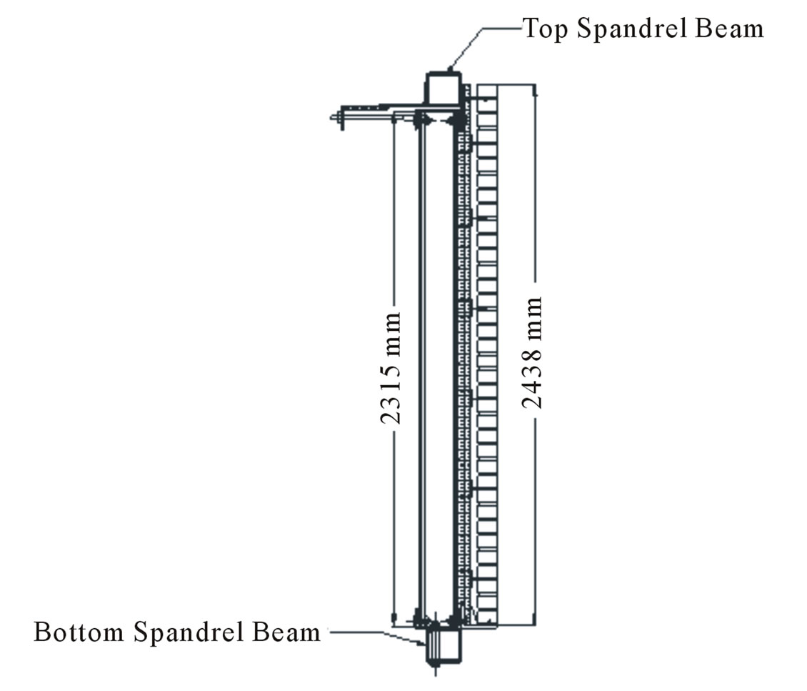
Figure 13. Elevation of seismic test specimen.
in this tie under 6.0 kN/m2 negative pressure reached 10.0 kN, which is much higher than the tie capacity, and the tie likely behaved nonlinearly. This suggestion was supported by the fact that many ties were actually pulled out during the test of the conventional specimen. The relationship between pressure and tie force for the PBVSS specimen did not have the same level of linearity
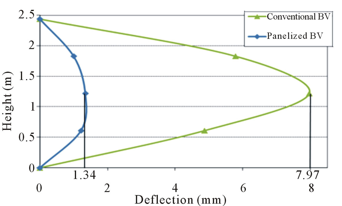
Figure 14. Comparison of deflection along height under 6 kN/m2 pressure.
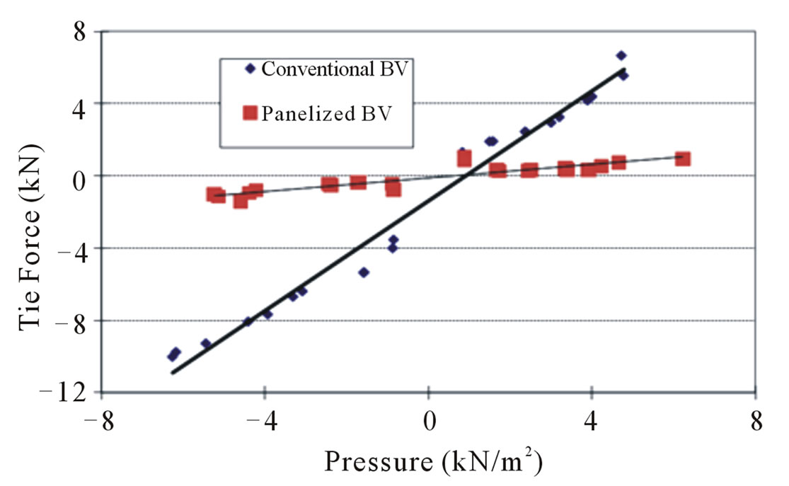
Figure 15. Tie force vs. pressure.
as that of the conventional specimen. Tie force distribution was not uniform for either specimen.
A crack along the whole length of the BV developed in the conventional specimen under 6.0 kN/m2 negative pressure. The crack closed during the positive pressure cycle and became even wider during the second negative pressure cycle. Some screws attaching the masonry ties to the SS were pulled out during the first negative pressure cycle and more ties were pulled out at the second cycle since less ties were engaged. Water leakage was observed in the water penetration test afterwards and a total of 0.454 kg of water was collected by the end of the test. The relatively small amount of water collected was due to the 0.48 kN/m2 positive pressure applied to the exterior face of the BV per ASTM E514 test standard [29]. However, the crack of the conventional specimen was formed under negative pressure. Hence the superimposed positive pressure during this water test closed the crack and decreased the amount of water penetration.
It seems that if negative pressure (instead of positive pressure) had been applied on the BV with wet exterior surface, much more water would have been collected. Furthermore, other than wind-driven rain, gravity, surface tension, kinetic energy, air currents, and capillary action may also cause water leakage once the wall cracks [18]. Therefore, under the simulated wind pressure of 6.0 kN/m2, the conventional specimen not only showed serviceability problem of cracking and water leakage, but also experienced safety-related damage due to the loss of reliable connection between the BV and the SS. However, this does not mean that in reality the conventional walls can withstand wind pressure up to 6.0 kN/m2. On the one hand, the BV of the test specimen was built with relatively hard hollow brick units. Hollow bricks generally have higher strength because of more uniform drying and burning. Moreover, the mortar squeezed in the holes during construction of the BV worked as shear keys and increased flexural cracking strength of the BV [35]. Moreover, due to the large movement of the test specimen, the silicone joints between the mockup perimeter and the test chamber experienced some tearing under the pressure of as low as 3.0 kN/m2. Therefore, in reality the conventional walls may start to have problems at much lower pressure level. The PBVSS specimen was tested up to 8.6 kN/m2 positive pressure and 6.0 kN/m2 negative pressure when the capacity of the test facility was reached. No damage was observed and no water leakage was collected during the water penetration test followed.
7. Discussion of the Racking Test Results
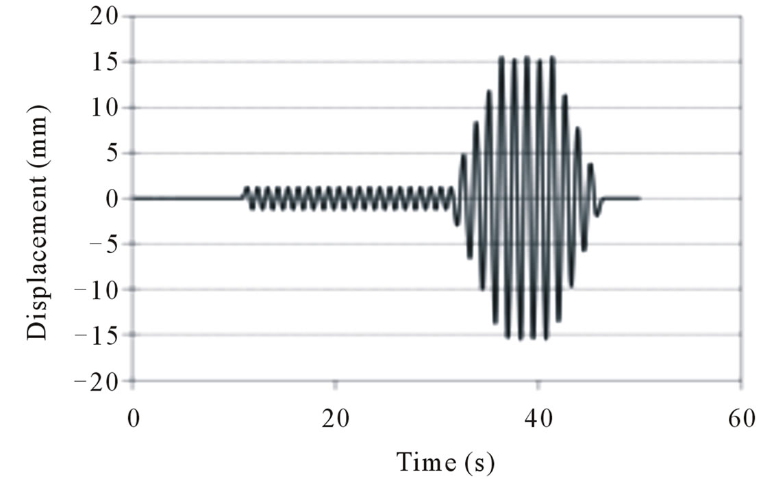
The specimen with 13 mm diameter threaded rods was tested first. Later, the 10 mm diameter threaded rods were attached and the specimen was tested again. Figure 16(a) shows one sample of input displacement versus time plots for 13 mm diameter rods at the 5th step with the input displacement of 15 mm. Figure 16(b) shows the corresponding load in the actuator vs. time for this step. The figure shows that at this step, it takes approximately 3.88 kN to move the specimen 15 mm, which is equivalent to a stiffness of 0.259 kN/mm. This value is quite small and shows that the BV wall does not effecttively participate in lateral load resistance, considering the in-plane stiffness of typical masonry walls [36]. Comparison of the load-time plots for the 13 mm tie rod (Figure 16(b)) with the plot for 10 mm tie-rod (not shown) showed that the magnitude of the peak load in the 13 mm tie-rod specimen plot was 24% higher than that for the 10 mm plot.
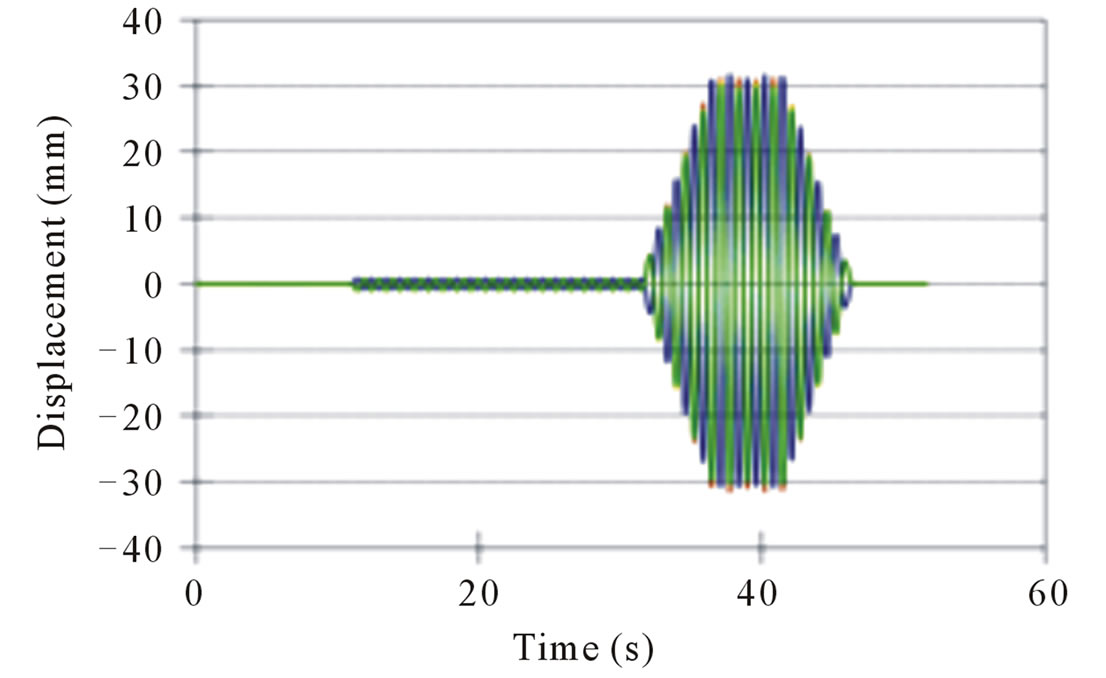
In-plane movements of all four BV corners were recorded during the test. Figure 17 shows displacement of the top left corner of the BV with 13 mm diameter threaded rods under 16mm input displacement during the 5th step. The measured displacement on the veneer is only very slightly smaller than the actuator input displacement (Figure 16(a)) and shows that the “plays” in the loading frame system is minimal. This was also further confirmed by looking at the plots of the displacements of the four corners of the BV wythe such as that shown in Figure 18(a) which shows the displacements of
 (a)
(a)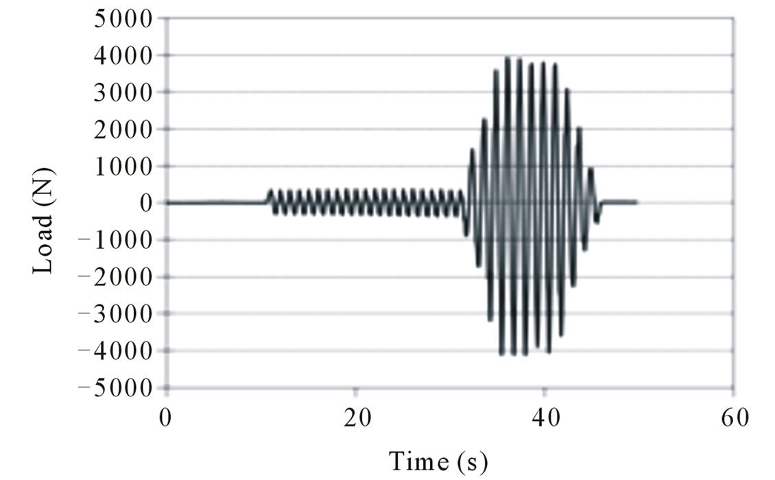 (b)
(b)
Figure 16. 13 mm diameter rods, 5th step; (a) Displacement vs. time; (b) Load vs. time.
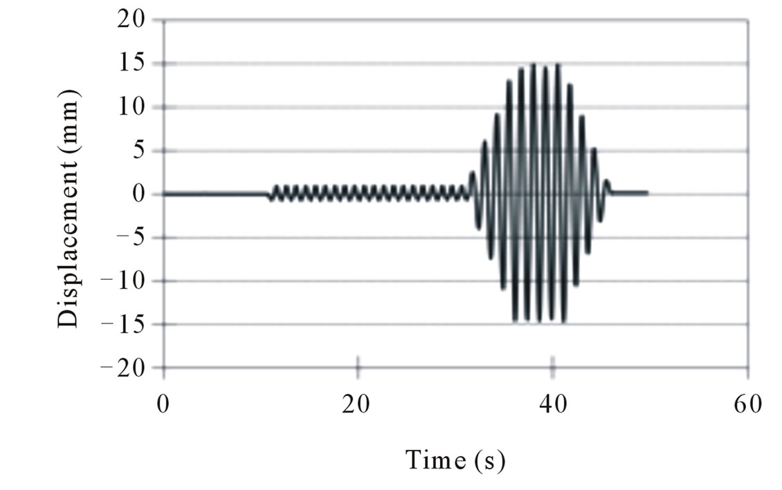
Figure 17. In-plane displacement of top left corner of the BV: 13 mm diameter rods, 5th step.
the specimen with 13 mm diameter tie-rods during the 10th step. Such corner plots indicated that there was no rotation of the BV. This is a desirable behavior for panelized walls under seismic effects because this means that adjacent panels will not touch each other during an earthquake (assuming input movements are the same for adjacent panels). Furthermore, the displacement of the top spandrel beam in the opposite direction (which was transferred to the steel angles of the connections) did not have any effect on the brick veneer. This is important for the panelized BV on steel framework backup wall system because it means that during an earthquake, the in-plane movement of the main structure system will not be transferred to BV. In other words, the connections can successfully isolate the BV from the movement of connections. Because there is no rotation of the BV, the shear ties will not take any shear force in the vertical direction due to the in-plane seismic movement.
Figure 18(b) shows the in-plane displacement of top corners of the steel frame for the specimen with 13 mm diameter threaded rods under 16 mm input displacement. The plots show that the magnitude of the steel frame displacement was the same as the input displacement, which indicates that the in-plane movement of the top spandrel beam did not have any effect on the steel frame either. Furthermore, since the two sensors had the same readings, the steel frame did not rotate either. Figures 18(c) and 18 (d) show comparison of the in-plane displacement of top left corner of the BV, top left corner of the steel frame, and the left tie-back connection during the 5th (16 mm displacement) and 10th (32 mm displacement) steps for the specimen with 10 mm dia. tie-back connection. These are points on the three components (BV, steel frame backup, and tie-back connection) on the left side approximately at the same elevation. Similar figures were obtained for the specimen with 13 mm tie-back connection. The plots show that absolute magnitudes of the three measurements are very close, and are approximately equal to the input displacement. However, at any given time, the displacement of the tie-back connection was in the opposite direction of that of the BV and the steel frame because the input displacement of the tieback connection was from the top spandrel beam and in the opposite direction to that of the bottom spandrel beam, which provided input displacement for the BV and the SS backup. The magnitude of the displacement of these three components are exactly the same as the input displacement, which means the displacement of the connection and the displacement of the main body of the PBVSS did not interfere with each other. The main body of the PBVSS was isolated from the input displacement of the tie-back connections.
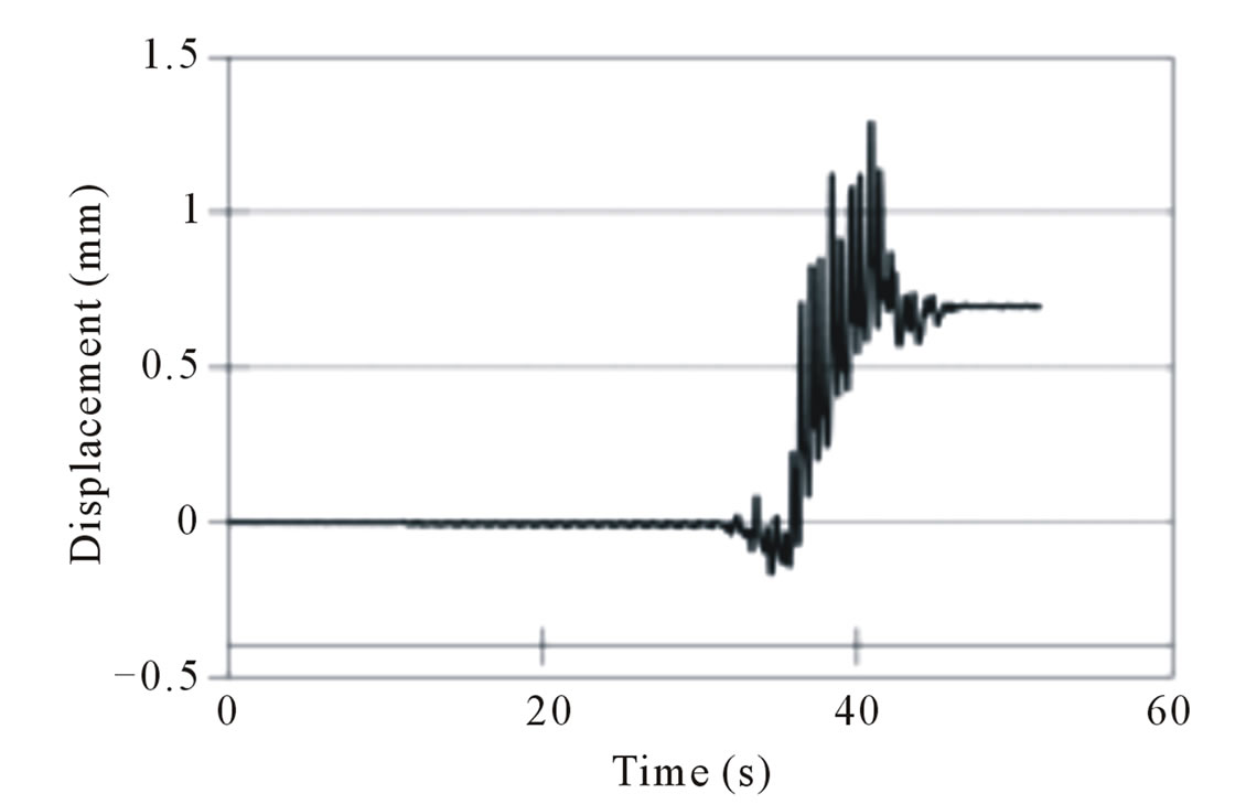
Figures 19(a) and 19(b) show the vertical and out-ofplane displacement of the specimen under 32 mm input displacement for the specimen with 13 mm diameter tieback. Similar displacements were also obtained for the
 (a)
(a)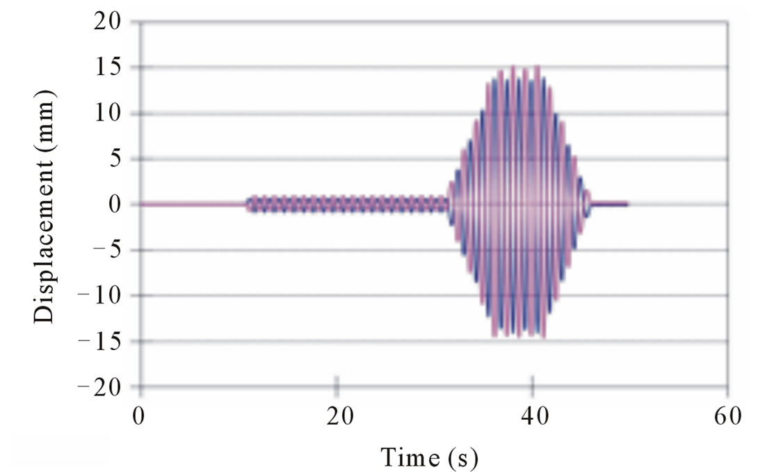 (b)
(b)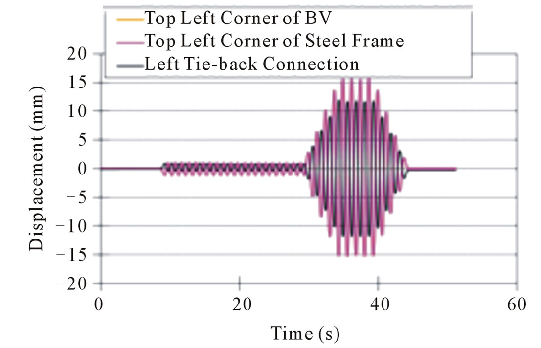 (c)
(c)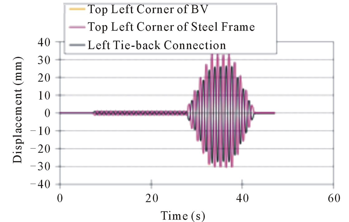 (d)
(d)
Figure 18. Comparison of in-plane displacement: (a) 13 mm diameter rods, 10th step; (b) Steel frame at corners: 13 mm Diameter rods, 5th step; (c) Top left corner of the BV, top left corner of the steel frame, and left tie-back connection: 10 mm diameter rods, 5th Step; (d) Top left corner of the BV, Top left corner of the steel frame, and left tie-back connection: 10 mm diameter rods, 10th step.
 (a)
(a)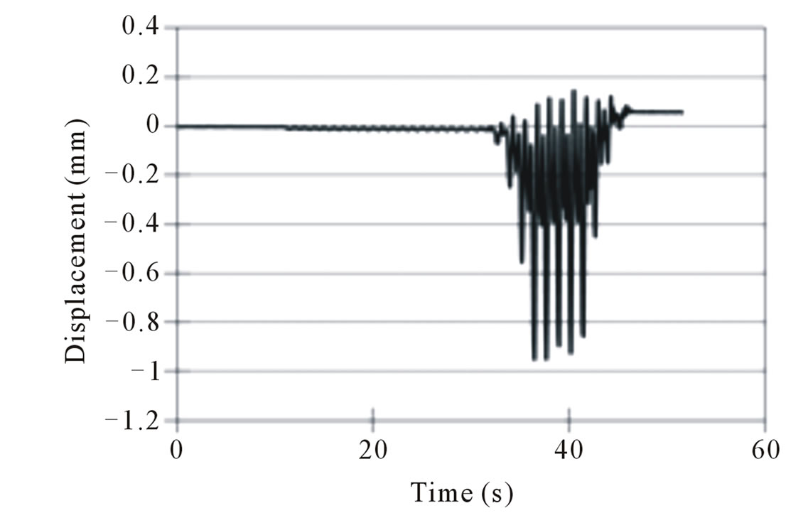 (b)
(b)
Figure 19. (a) Out-of-plane displacement of BV top right corner: 13 mm diameter rods, 10th step; (b) Vertical displacement of bottom of the BV: 13 mm diameter rods, 10th step.
specimen with 10 mm diameter tie-back. As expected, movements in these two directions were negligible. The specimen moved as a rigid body horizontally without any vertical or out-of-plane movement. Therefore, there was no contact between the steel plate at the top and the top spandrel beam either.
The failure mode of the tie-back in both specimens was by shearing off of the threaded rods at large drifts. The threaded rods sheared off at the points that they were connected to the top channel of the PBVSS, as shown in Figure 20. In the test of specimen with 13 mm diameter threaded rods, two of the threaded rods failed at the 11th step, which had the maximum wall drift of about 70 mm and a corresponding load of 5.34 kN. The left and the middle tie-back connections sheared off at approximately the same time, while the right connection was still good. The specimen with 10 mm threaded rods experienced shearing off of the left tie-back connection first at the 10th step, with the maximum wall drift of about 64 mm and a corresponding load of about 6.03 kN. The test was then continued with larger displacement and eventually the middle tie-back connection sheared off too at the 14th step with the maximum wall drift of about 88mm and the corresponding load of about 10.0 kN. In both cases, no vertical or out-of-plane movement was recorded. The BV moved horizontally as a whole rigid body. It was not affected by the movement of the top spandrel beam at all. No crack or other form of damage of the BV was noticed.
The tests therefore showed that the design of the connections can isolate the BV from seismic movement of the main structure of buildings. By comparing the two cases, although the left tie-back connection of the specimen with 10 mm diameter threaded rods broke earlier (during the 10th step versus the 11th step for the specimen with 13 mm diameter threaded rods), it could still take higher displacement with the remaining two connections. Eventually, the middle connection failed at a larger displacement than the specimen with 13 mm diameter threaded rods. It also took more load to break the specimen with 10 mm diameter threaded rods. Finally, Figures 21(a) and 21(b) show the hysteretic displacement versus load curves for different steps of both cases. In both cases, the stiffness of the specimen decreased with increased input displacement, more so for the specimen with 10 mm diameter threaded rods.
8. Summary and Conclusions
To evaluate the performance of the proposed PBVSS wall system under lateral forces, simulated out-of-plane wind pressure and in-plane racking load tests were carried out on a full-scale specimen. A conventional BV/SS specimen was also tested under simulated wind pressure for comparison. The simulated wind load tests showed that due to the stiffer and more integral SS backup used, the deflection of the PBVSS specimen was much less than that of the conventional one. The stiffer shear connectors used in the PBVSS design could transfer loads more efficiently from the BV to the SS backup. Consequently, the PBVSS showed higher level of composite action resulting in reduction of the maximum deflection of the wall panel.
The conventional BV cracked at a negative pressure of 6.0 kN/m2 and water leakage was observed. Some masonry ties were also pulled out of the SS. The specimen showed both serviceability and safety-related problems. The PBVSS specimen, however, showed no damage during the tests. In order to establish design guidelines to achieve different performance levels under out-of-plane loading, including composite behavior and two-way action, more tests as well as detailed finite element analysis with various configurations of SS backup and tie patterns should be performed. Furthermore, tests of multiple side-by-side panels with joints will also help better understanding of the performance of the proposed PBVSS
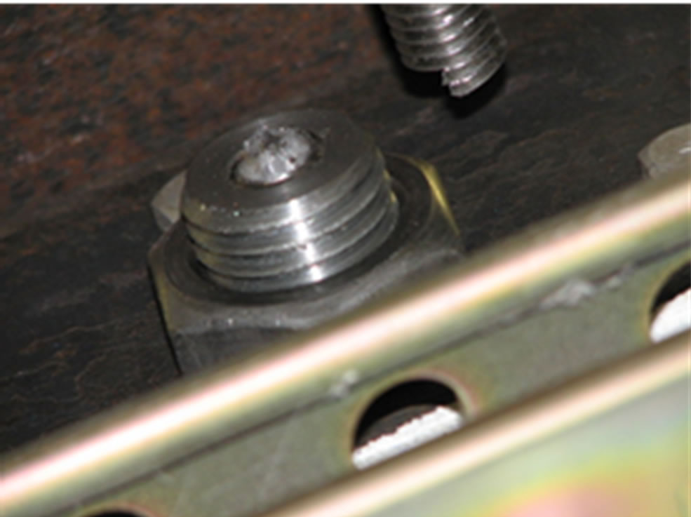
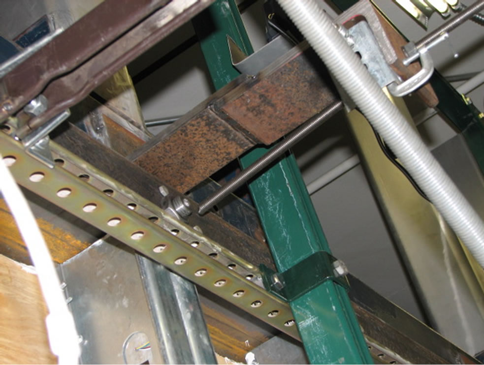
Figure 20. Typical failure mode of tie-back threaded rods.
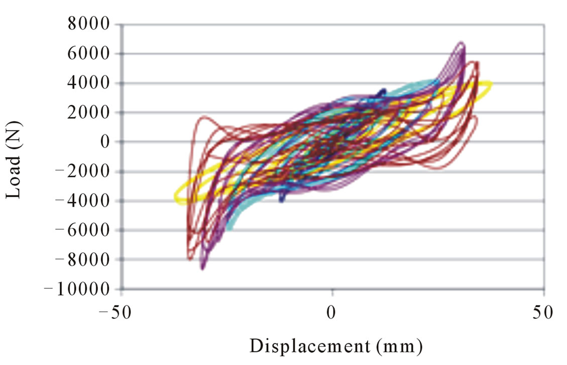 (a)
(a)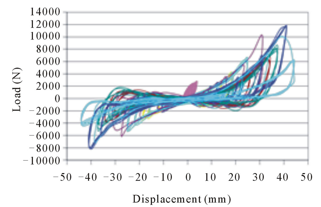 (b)
(b)
Figure 21. (a) Hysteresis curve for specimen with 13 mm diameter threaded rods; (b) Hysteresis curve for specimen with 10 mm diameter threaded rods.
system for practical applications.
During the in-plane racking test of the PBVSS specimen, threaded rods with two different diameters, 13 mm and 10 mm, were separately used on the PBVSS wall system to evaluate the effect of cross sectional areas of threaded rods on the performance of the system. The experiments were carried out in a displacement-control mode. The tests basically validated the design concept and confirmed what was expected, that is, no damage to the BV under cyclic racking displacement and minimal lateral load resistance of the panelized wall.
As to the performance of the wall system when compared with the ASCE 7-10 [28] drift limit, the drift capacity of the tie-back connections are just slightly larger than the code maximum values. The code drift ratio limit of 2.5% is equivalent to a drift value of 61mm for the specimen tested (with 2438 mm high). The input displacement for failure of the first 13mm diameter and 10mm diameter threaded rods were, respectively, 70 mm and 64mm. Although these failure drift values do not show large margins beyond the maximum code drift level, it should be noted that the drift capacity of threaded rods is a function of the material strength, length of the threaded rod, and diameter of the threaded rod. With further testing of isolated tie-back connections, one can determine the optimum design parameters. Furthermore, since several tie-backs are used in PBVSS wall panels and other rods generally fail at higher drifts than the first failed rod, there is redundancy built in the design.
The main conclusion of the racking load test study is that the concept of developing a panelized BV with SS backup system to provide seismic isolation in the sense of preventing damage to the BV is practical. It is expected that with further refinement of the design, this wall system can be used for practical applications. The lateral connection system of flexible rods is shown to be practical in creating a seismic isolation design. However, connections can take different forms, with tie-back being only one type. Further study of the isolated lateral connection for improved and increased drift capacity is recommended.
9. Acknowledgements
The study presented was partially supported by General Services Administration. The support of General Services Administration is gratefully acknowledged. The views expressed in this paper are those of the authors and do not necessarily represent those of the General Services Administration.
REFERENCES
- Brick Industry Association (BIA), “Brick Veneer/Steel Stud Walls, Technical Notes on Brick Construction,” Reston, 1999.
- L. Brock, “Designed for Durability: Case Study of Anchored Brick Veneer that Meets Technical and Aesthetic Requirements,” Proceedings of the 7th North American Masonry Conference, The Masonry Society, Boulder, 1996, pp. 117-128.
- J. W. Cowie, “Failure of Steel Studs,” Magazine of Masonry Construction. Vol. 3, No. 2, 1990, pp. 82-84.
- A. A. Hamid, I. J. Becica and H. G. Harris, “Performance of Brick Masonry Veneers,” Proceedings of the 7th International Brick Masonry Conference, Melbourne, 1985, pp. 321-331.
- I. Jalil, W. Kelm and R. E. Klingner, “Performance of Masonry and Masonry Veneer Buildings in the 1989 Loma Prieta Earthquake,” Proceedings of the 6th North American masonry Conference, The Masonry Society, Boulder, 1993, pp. 681-692.
- W. M. McGinley and C. L. Ernest, “Façade Inspection a Must for Both New and Old Buildings—A Case Study of Two High Rise Structures,” Journal of ASTM International (JAI), Vol. 1, No. 3, 2004, 15 p.
- A. E. Schultz, M. Porter, O. Bigelow and R. Stehly, “Masonry Building Performance during the March 29, 1998 Southern Minnesota Tornadoes,” Proceedings of the 8th North American Masonry Conference, 1999, Boulder, The Masonry Society, 1998, pp. 797-808.
- M. Memari, M. Aliaari and A. A. Hamid, “Evaluation of Seismic Performance of Anchored Brick Veneer Walls,” In: P. G. Johnson, Ed., Performance of Exterior Building Walls, ASTM STP 1422, American Society of Testing and Materials, West Conshohocken, 2002, pp. 115-131.
- J. Liang, “Development of a Multihazard Resistant Panelized Brick Veneer Wall System,” Ph.D. Dissertation, The Pennsylvania State University, University Park, 2006.
- J. Liang and A. M. Memari, “Full-Scale Experimental Evaluation of a Panelized Brick Veneer Wall System under Simulated Wind Loading,” Structural Engineering and Mechanics Journal, Vol. 38, No. 1, 2011, pp. 99-123.
- J. Liang, and A. M. Memari, “Finite Element Analysis of a Panelized Brick Veneer Wall System and Comparison with Wind Load Testing Results,” The Masonry Society Journal, Vol. 28, No. 1, 2010, pp. 7-28.
- C. T. Grimm and R. E. Klingner, “Crack Probability in Brick Masonry Veneer over Steel Studs,” Proceedings of the 5th North American Masonry Conference, The Masonry Society, Boulder, 3-6 June 1990, pp. 1323-1334.
- M. J. Wilson and R. G. Drysdale, “Structural Test Results for Full Scale BV/SS,” Proceedings of the 5th North American Masonry Conference, The Masonry Society, Boulder, 1990, pp. 1335-1346.
- W. M. McGinley, J. Warwaruk, J. Longworth and M. Hatzinikolas, “Masonry Veneer and Steel Stud Curtain Walls,” Proceedings of the 4th Canadian Masonry Symposium, Fredericton, New Brunswick, 1986, pp. 730-743.
- T. Kelly, M. Goodson, R. Mayes and J. Asher, “Analysis of the Behavior of Anchored Brick Veneer on Metal Stud Systems Subjected to Wind and Earthquake Forces,” Proceedings of the 5th North American Masonry Conference, The Masonry Society, Boulder, 1990, pp. 1359- 7130.
- G. T. Suter, R. G. Drysdale and H. Keller, “Canadian Research on the Brick Veneer/Steel Stud Wall System,” Proceedings of the 5th North American Masonry Conference 1990, The Masonry Society, Boulder, 1990, pp. 1287-1301.
- J. Straube, “Pressure Moderation and Rain Penetration Control,” Proceedings of the Ontario Building Envelope Council (OBEC) Pressure-Equalized Rainscreen (PER) Seminar 2001, University of Waterloo, Waterloo, Ontario, 2001, pp. 1-51.
- KPFF Consulting Engineers, “Design Guide for Anchored Brick Veneer over Steel Studs,” Prepared for Western States Clay Products Association, Los Angeles, 1995.
- M. A. Postma, “Structural Considerations in the Remediation of Brick Veneer/Steel Stud Wall Systems,” Master Thesis, University of Waterloo, Waterloo, 1993.
- M. Bruneau, “Performance of Masonry Structures During the 1994 Northridge (Los Angeles) Earthquake,” Canadian Journal of Civil Engineering, Vol. 22, No. 22, 1995, pp. 378-402. doi:10.1139/l95-048
- G. Magenes and G. M. Calvi, “Cyclic Behavior of Brick Masonry Walls,” Proceedings of the 10th World Conference of Earthquake Engineering, Balkema, Rotterdam, 1992, pp. 3517-3522.
- G. Magenes and G. M. Calvi, “In-Plane Seismic Response of Brick Masonry Walls,” Earthquake Engineering and Structural Dynamics, Vol. 26, No. 11, 1997, pp. 1091-1112. doi:10.1002/(SICI)1096-9845(199711)26:11<1091::AID-EQE693>3.0.CO;2-6
- A. M. Memari, E. F. P. Burnett and B. M. Kozy, “Seismic Performance of Masonry Ties Used in Brick Veneer Walls,” Construction and Building Material Journal, Vol. 16, No. 7, 2002, pp. 397-407. doi:10.1016/S0950-0618(02)00042-9
- Fero, “Engineered Masonry Connectors and Accessories,” 2012. http://www.ferocorp.com
- R. A. McCann, “Architectural Precast Concrete Cladding Connections in High Seismic Areas,” Prestressed Concrete Manufacturers Association of California (PCMAC) Technical Update, Glendale, 1995.
- J. Liang and A. M. Memari, “Finite Element Analysis of a Panelized Brick Veneer Wall System and Comparison with Wind Load Testing Results,” The Masonry Society Journal, Vol. 28, No. 1, 2010, pp. 7-28.
- American Society for Testing and Materials (ASTM) International, “Standard Test Method for Structural Performance of Exterior Windows, Curtain Walls, and Doors by Cyclic Static Air Pressure Differential,” E 1233-00, Vol. 04.11, ASTM, West Conshohocken, 2000.
- American Society of Civil Engineers (ASCE), “Minimum Design Loads for Buildings and Other Structures,” ASCE 7-10, Reston, 2010.
- American Society for Testing and Materials (ASTM) International, “Standard Test Method for Water Penetration and Leakage through Masonry,” E 514-03c, Vol. 04.05, ASTM, West Conshohocken, 2005.
- American Architectural Manufacturers Association (AAMA), “Recommended Dynamic Test Method for Determining the Seismic Drift Causing Glass Fallout from a Wall System,” Publication No. AAMA 501.6-09, Des Plaines, 2009.
- D. R. Getz and A. M. Memari, “Static and Cyclic Racking Performance of Autoclaved Aerated Concrete Cladding Panels,” Journal of Architectural Engineering, Vol. 12, No. 1, 2006, pp. 12-23. doi:10.1061/(ASCE)1076-0431(2006)12:1(12)
- American Society for Testing and Materials (ASTM) International, “Standard Test Methods of Conducting Strength Tests of Panels for Building Construction,” E72- 05, Vol. 04.11, ASTM, West Conshohocken, 2005.
- American Society for Testing and Materials (ASTM) International, “Standard Practice for Static Load Test for Shear Resistance of Framed Walls for Buildings,” E564- 06, Vol. 04.11, ASTM, West Conshohocken, 2006.
- Hohmann and Barnard, “Hohmann and Barnard Inc.,” 2012. www.h-b.com
- N. Taly, “Design of Reinforced Masonry Structures,” McGraw-Hill, New York, 2000.
- M. Aliaari and A. M. Memari, “Experimental Evaluation of a Sacrificial Seismic Fuse Device for Masonry Infill Walls,” ASCE Journal of Architectural Engineering, Vol. 13, No. 2, 2007, pp. 111-125. doi:10.1061/(ASCE)1076-0431(2007)13:2(111)