Modern Mechanical Engineering
Vol.3 No.2(2013), Article ID:31650,6 pages DOI:10.4236/mme.2013.32014
The Influence Factors Study of Aerosol Particles
1Military Representative Office, Dalian, China
2China Ship Development and Design Center, Wuhan, China
Email: justin96161@gmail.com
Copyright © 2013 Tao Jiang, Wu Wei. This is an open access article distributed under the Creative Commons Attribution License, which permits unrestricted use, distribution, and reproduction in any medium, provided the original work is properly cited.
Received March 21, 2013; revised April 23, 2013; accepted May 7, 2013
Keywords: The Generating Device of Salt Spray Aerosol; Nozzle; Atomization Mechanism; Numerical Simulation
ABSTRACT
The marine and coastal intake filtration device is mainly used to filter out the salt spray aerosol particles. So, the laboratory studies of the intake filtration device need to simulate the salt spray aerosols state of the ocean environment. But the distribution of ocean salt spray aerosol particle of diameter is very wide, so the simulation device of salt spray aerosol should produce a variety of salt spray aerosol particles. The paper is to mainly study the influencing factors of salt spray aerosol device to produce different particles diameter. And the investigation and study mainly include two aspects: numerical simulation and experimental study.
1. Introduction
Since the marine atmosphere contains salt, which exists in the form of aerosol, the air intake of marine ship usually has the desalination requirements [1]. Currently, many large surface ships are equipped with gas turbine power, both at home and abroad. The desalination requirements of the air intake of gas turbine, which has a greater air intake, are more stringent. All of these require designers to do numerical simulation and experimental study to marine filtration device of desalination purposes in the appropriate ocean state. That can provide a basis for the design and manufacture of high-performance marine filter. The paper examines the factors of salt spray aerosol device of producing different diameter particle based on the actual development requirements of air intake filter and also conducts the mechanism study from numerical simulation and experimental study. The paper do the numerical simulation of the nozzle gas-liquid twophrase flow field with a discrete phrase model (DPM) [2], taking the Reynolds average N-S equation as the control equation and the standard model as the turbulence model. In the boundary conditions, the inlet pressure of gas field, the initial diameter and initial velocity of droplets’ inlet mass flow of a discrete phrase are given and also the outlet pressure of cylindrical space is given. Maintain the mass flow rate of the inlet droplets and study the influence law of salt spray aerosol particle diameter while changing the inlet pressure. Maintain the intake pressure and study the influence law of salt spray aerosol particle diameter while changing the mass flow rate of the inlet droplets.
The Mathematical Model of Nozzle Flow Field
First, to conduct the numerical simulation of the nozzle internal and external flow field, we establish a mathematical model of fluid flow in the nozzle. It includes turbulent flow model and laminar flow model [3].
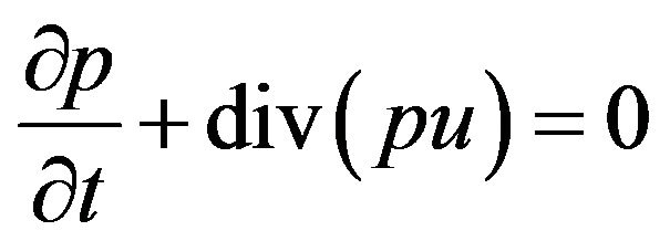
Any liquidity issues meet the conservation of mass [4]. That’s to say, the increase mass of fluid micro unit is equal to the inflow net mass of the micro unit in a period of time. Set the direction components of speed vector u are u, v, w in the direction of x, y, z. So, the mass conservation equation is
 (1)
(1)
Supposing
 (2)
(2)
The vector expression of Formula (1) is
 (3)
(3)
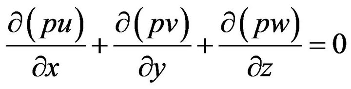
This equation is the continuity equation of the flow.
Due to the water’s little compressibility, it can be regarded as incompressible fluid. Provided the water’s density 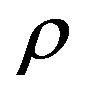 being constant, when the flow is in a steady state,
  doesn’t change with the time. So
The momentum conservation equation in the direction of x, y and z are
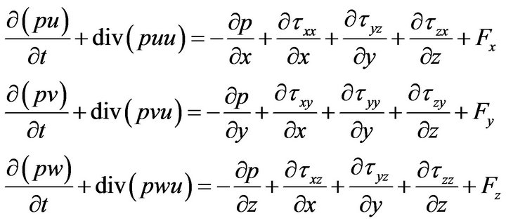 (4)
(4)
where  are the component of viscous stress
  in the surface of the micro unit. F is the physical of the micro unit.
Equation (4) can also be written as follows:

The Formulas (3) and (4) are the momentum conservation equation. They can also be simplified as momentum equation, motion equation or Navier-Stokes equation.
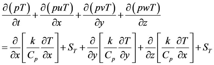
Provided that the fluid’s specific heat capacity is Cp, temperature is T, the heat transfer coefficient is k, the viscous dissipation is ST, and its energy conservation equation can be expressed as
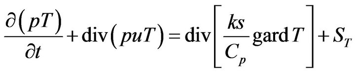 (5)
(5)
Expanding to
From macroscopic aspect, laminar flow is regular viscous fluid motion. Laminar flow fluid is approximate the ideal fluid, so you can solve the equation directly from the N-S equation. Turbulence is the most ubiquitous fluid motion in nature and engineering. Its movement is very irregular, very unstable and the speed of its every point is immediately changeable [5]. Although the three-dimensional transient N-S equations apply equally, we still have to adopt the direct simulation method which has a high demand to computer if we solve the control equation of three-dimensional transient directly. However, this method doesn’t used in the project currently. The method which is widely used in the engineering is the time averaging processing of the transient N-S equation. That is, take the turbulent motion as the superposition of two motions. One is the time average flow and the other is the instantaneous pulsating flow. Meanwhile [6], add the turbulent kinetic energy equation and turbulent dissipation rate equation which can reflect the turbulence characteristics. Here, k is to express turbulent kinetic energy and  is to express turbulent dissipation rate. Taking the following equation:
In the standard equation of  , k and
  is the unknown quantity. The corresponding operation equation is:
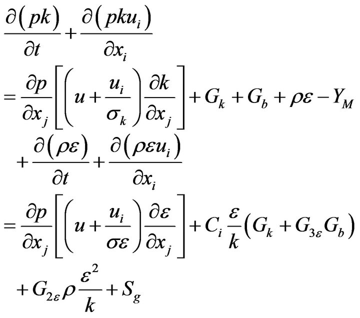 (6)
(6)
In order to analyze the control equation and the solving of the various control equation with same procedures, the general forms of the basic control equation of fluid power are established [7].
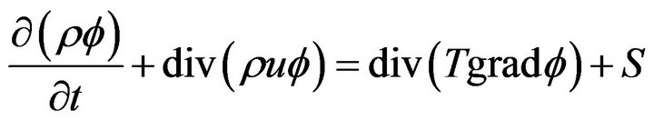 (7)
(7)
Expanding to

2. Geometric Model and Mesh Division
Using Gambit to establish the simplified geometric model of the internal and external flow field of the nozzle (such as Figures 1 and 2).
The CFD method for solving control equation is actually to discrete the control equation in the space area and then obtain the discrete equations by solving them [8,9]. To discrete the control equation in the space domain, the grids must be used. So you have to grid the established the model, determine the size and type of the cell and also define the relevant boundary conditions before the solving of CFD [10] (such as Figures 3 and 4).
3. Numerical Simulation Results and Experiments
The paper mainly studies the influence law of the nozzle’s atomized particle size when the pressure of the inlet air and the mass flow rate of the inlet droplets are changed. First, maintain the intake pressure and study the influence law of salt spray aerosol particle diameter while changing the mass flow rate of the inlet droplets. Second, maintain the mass flow rate of the inlet droplets and study the influence law of salt spray aerosol particle diameter while changing the inlet pressure (such as Figures 5 and 6).
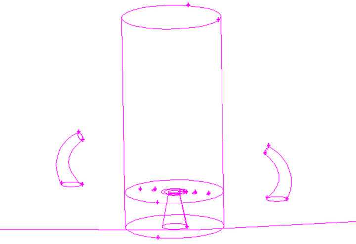
Figure 1. The partially enlarged view of internal and external flow field of the nozzle’s simplified model.

Figure 2. The simplified geometric model of the nozzle’s internal and external flow field.
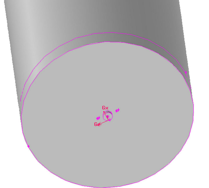
Figure 3. The contour model diagram.
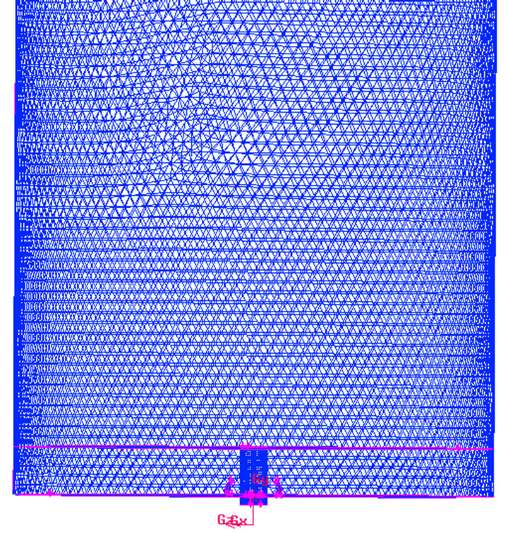
Figure 4. The grid map of the nozzle’s internal and external flow field.
Figure 5. The spray velocity vector diagram.
Provided that the inlet air pressure is 105,325 Pa, the initial particle diameter is 0.03 mm, the initial particle velocity is 10 m/s, we can obtain the cross-sectional velocity vector diagram, the cross-sectional velocity contours diagram, the nozzle atomization particle size diagram when the mass flow rate of the inlet droplets are 0.6 g/s,

Figure 6. The spray particle size diagram.
0.8 g/s, 1 g/s, 1.5 g/s respectively. Finally, the influence law of atomization particle can be concluded about the mass flow rate of the inlet droplets.
As the Figure 4 showed, the maximum speed of the spout gas can be 77.1 m/s when the mass flow of the inlet droplets is 0.6 g/s. The atomization particle diameter is among 0.03 mm and 0.06 mm as the Figure 4 showed.
The maximum speed of the spout gas can be 77.1 m/s when the mass flow of the inlet droplets is 0.8 g/s and the atomization particle diameter is among 0.03 mm and 0.0723 mm. The maximum speed of the spout gas can be 77.1 m/s when the mass flow of the inlet droplets is 1 g/s and the atomization particle diameter is among 0.03 mm and 0.074 mm. When the mass flow of the inlet droplets is 1.5 g/s, the atomization particle diameter is among 0.03 mm and 0.0828 mm.
In summary, when the intake air pressure is constant, the spray particles diameter of the nozzle will increase with the increase of the mass flow of the inlet droplets.
As the Figure 7 showed, the maximum speed of the spout gas can be 66.8 m/s when the intake air pressure is 104,325 Pa and the atomization particle diameter is among 0.03 mm and 0.102 mm, as the Figure 8 showed.
The maximum speed of the spout gas can be 77.1 m/s when the intake air pressure is 105,325 Pa and the atomization particle diameter is among 0.03 mm and 0.0723 mm. The maximum speed of the spout gas can be 108 m/s when the intake air pressure is 109,325 Pa and the atomization particle diameter is among 0.03 mm and 0.0624 mm.
In summary, when the mass flow of the inlet droplets is constant, the outgas velocity increases, the atomization effects become well and the particle diameter decrease with the increase of the intake air pressure.
The environment parameters of the experiment are as follows: the atmospheric pressure is 99.50 kPa and the environment temperature is 30.6 degrees Celsius.
The spray particle diameter and particle velocity distribution diagram are showed as Figure 9 when the mass
Figure 7. The velocity vector diagram.

Figure 8. The particle atomization diameter diagram.

Figure 9. The spray particle diameter and particle velocity distribution diagram.
flow of inlet droplets is 0.013 kg and the intake air pressure is 111.23 kPa.
The spray particle diameter and particle velocity distribution diagram are showed as Figure 10 when the mass flow of inlet droplets is 0.033 kg and the intake air pressure is 111.30 kPa.
The spray particle diameter and particle velocity distribution diagram are showed as Figure 11 when the mass flow of inlet droplets is 0.041 kg and the intake air pressure is 111.69 kPa.
The spray particle diameter and particle velocity distribution diagram are showed as Figure 12 when the mass flow of inlet droplets is 0.060 kg and the intake air pressure is 332.18 kPa.
The spray particle diameter and particle velocity distribution diagram are showed as Figure 13 when the mass flow of inlet droplets is 0.67 kg and the intake air pressure is 462.81 kPa.
The data also can be expressed as the Table 1 showed.
From the Table 1, the following conclusion can be drawn. That’s, from the first three data sets, the average particle diameter increases with the increase of the mass flow of the inlet droplets when the intake air pressure is constant. And from the latter three data sets, the average particle diameter decrease with the increase of the intake air pressure when the mass flow of the inlet droplets is constant.
4. Conclusions
The paper mainly studies the factors of the salt spray

Figure 10. The spray particle diameter and particle velocity distribution diagram.
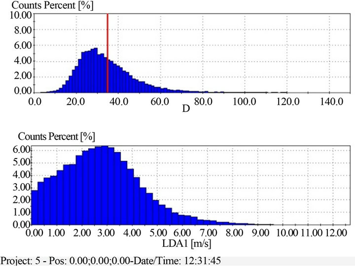
Figure 11. The spray particle diameter and particle velocity distribution diagram.
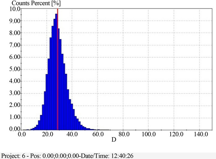
Figure 12. The spray particle diameter and particle velocity distribution diagram.

Figure 13. The spray particle diameter and particle velocity distribution diagram.
Table 1. The distribution table of spray particle diameter.
aerosol device to produce different diameter particles. It mainly includes two aspects (the mass flow of the inlet droplets and the intake air pressure). On the basis of the analysis of the nozzle atomization mechanism and the learning of the existing nozzle, the paper conducts the numerical simulation to a given nozzle through the software. By the simulation of the nozzle’s internal and external flow field, the flow and air flow characteristics of the nozzle’s internal and external flow field are obtained. By the analysis of the cross-sectional velocity vector diagram, the cross-sectional velocity contours diagram, the nozzle atomization particle size diagram, the influence law of salt spray aerosol device to produce different diameter particles can be concluded about the mass flow rate of the inlet droplets and the intake air pressure. Finally, the influence laws of the two factors are verified by the combination of the experiment summary. That’s1) The nozzle’s spray particles diameter increases with the increase of the mass flow of the inlet droplets when the intake air pressure is constant;
2) when the mass flow of the inlet droplets is constant, the outgas velocity increases, the atomization effects become better and the particle diameter decreese with the increase of the intake air pressure.
REFERENCES
- P. Aeroso, “Measurement, Priciples, Technologies, and Applications,” Chemical Industry Press, Beijing, 2007.
- Z. Z. Han, “FLUENT Fluid Simulation Examples and Application,” Beijing Institute of Technology Press, Beijing, 2004.
- F. J. Wang, “Computational Fluid Dynamics Analysis,” Tsinghua Press, Beijing, 2004.
- L. J. Wang, “Study of High Pressure Water Mist Nozzle and Fire Extinguishing Performance,” Huazhong University of Science and Technology, Wuhan, 2005.
- D. F. Che, “A Number of Flow and Its Application,” Xi’an Jiao Tong University Press, Xi’an, 2007.
- J. Cai, “Air filter ABC,” China Building Industry Press, Beijing, 2002.
- D. X. Cheng, “Mechanical Design Manual,” Chemical Industry Press, Beijing, 1969.
- Q. L. Hui, “Wind Tunnel Testing,” National Defence Industry Press, Beijing, 2000.
- L. Y. Hou and X. C. Hou, “Nozzle Technology Handbook,” Sinopec Press, Beijing, 2002.
- C. Wu, X. Y. Zhou and G. W. Wu, “Eddy Pressure Nozzle and Its Application in Spray Granulation in Fluidized Bed,” Chemical Equipment Technology, Vol. 24, No. 2, 2003, pp. 4-7.