Modern Mechanical Engineering
Vol.3 No.1(2013), Article ID:28258,6 pages DOI:10.4236/mme.2013.31006
Study of Stress Sources and Critical Stress Combinations for the Input Shaft of a Longitudinally Mounted Four Speed Automotive Automatic Transmission Model
Automotive Engineering Department, Faculty of Engineering, Helwan University, Cairo, Egypt
Email: nagwaibrahim2006@yahoo.co.uk
Received August 23, 2012; revised October 18, 2012; accepted November 2, 2012
Keywords: Longitudinally Mounted Automotive Automatic Transmission; Input Shaft Stresses; Torque Converter Torque Ratio; Torque Converter Weight; Simple Planetary Gear Set Weight
ABSTRACT
In the present paper; two models of the input shaft for a Longitudinal Mounted four Speed Automotive Automatic Transmission for the first time were introduced to describe the input shaft critical loads. In the first model; the DC (Direct Clutch) connects two gears together. This gives no change in the set torque (the set output torque equal to the set input torque). In the second model; the ODB (Over Drive Brake) fixes one element of the planetary set. This is resulting, the gear set gives reduction ratio (the set output torque is not equal to the set input torque). So, the transmission input shaft is worked under two different working operating conditions of torque. Also, it is loaded by a two vertical loads which are coming from the turbine and planetary set loads respectively. They are shown that there are three critical combinations of forces (contact force, shear force, and normal force) applied on the input shaft. The critical forces can be possibility exist three types of cracks for the input shaft cross section they are: transverse (torsion stress), longitudinal (bending stress), and vertical (shear stress). The three cracks are studied in this article. The article considers three stress factors: shearing torsion stress, shear stress, and bending stress.
1. Introduction
In study of stress sources and critical stress combinations of the input shaft for the present longitudinally mounted four speed automotive automatic transmissions, which they are resulting in failure. It is common to focus on the main loads acting on the spline part of the input shaft which are forces due to the turbine torque and turbine weight, and also focus on the loads acting on the solid part of the input shaft which are forces due to the planetary set torque (the maximum set torque is occurred at the brake set is applied) and the planetary set weight respectively [1].
Turbine forces are transmitted to the input shaft through the spline part. For the simplest calculations it is assumed that the turbine transmits force and torque to the spline part of the shaft at the middle of its width, and study the stressed-strained is based on the corresponding cross-section. Although, actually, turbine force of interaction between the turbine hub and the spline shaft part is distributed along the length of the turbine hub. Also, the planetary set force is distributed along the bearing of the set.
Forces on the input shaft for the mentioned longitudinal mounted four speed automatic transmission induce stresses which are of torsional, bending, shearing, and axial nature. In studies of stressed-strained states of the input shaft resulting in fatigue failure, it is common to forces on the input shaft induce stresses which are of a torsional, bending, shearing, and axial nature. focus primarily on torsion phenomena. In so doing, torsional shear stresses are considered for the most part. The effect of axial forces is usually not significant and can be omitted.
2. Basic Concepts
The longitudinally four speed automatic transmission Figure 1 input shaft is flowed the torque converter turbine torque to a simple planetary gear set. The turbine torque is varied according to the variation of the pump torque. The turbine torque variation has two categories. The first one is given at low torque converter speed ratio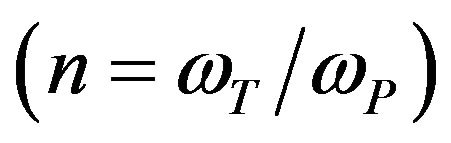 . Where, the ratio of the turbine and pump torques is given by the Equation [2]:
The second stage is occurred when the torque converter lock-up clutch is activated (at the design point), the turbine and pump are connected to the engine output. The angular velocity and torque of turbine are expressed as follows [3]:
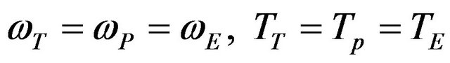 .
.
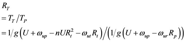
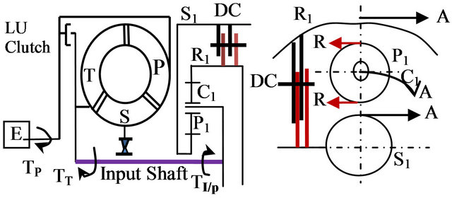
The resistant torque of the planetary gear set for the turbine torque has two values. One value occurs when the DC clutch is applied Figure 2 and its value is:
 .
.
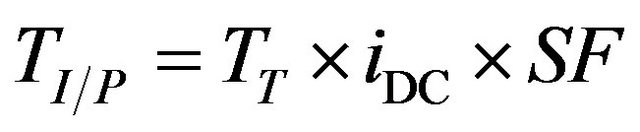
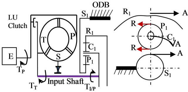
The other value is occurred when the ODB brake is applied Figure 3 and the input shaft resistance torque is become:
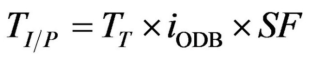 .
.
The turbine torque (TT) transmits through a spline part on the input shaft Figure 4 effect on the whole shaft until the carrier bearing. The spline part of the shaft affected manly torsion moment (no bending).
Diagrams of bending moment Mb, caused by turbine weight (W1) and first planetary gear set (W2), and shear force (Fs), are shown in Figure 5.
Hence, the diagrams of contact forces from torsion  are shown in Figure 6(a). Diagram of torsional moment
 , caused by contact forces from torsion is shown in Figure 7. For any tooth since
  and
and  are
are
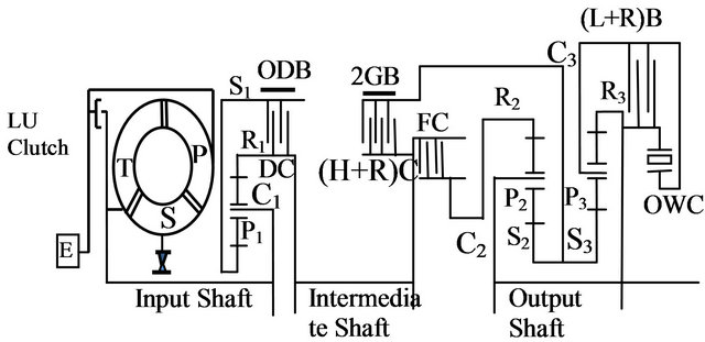
Figure 1. A longitudinally mounted four speed automotive automatic transmission model [3,4].
 (a) (b)
Figure 2. Input shaft model with dc clutch (a) Side view; (b) Plan view.
 (a) (b)
Figure 3. Input shaft model with ODB brake (a) Side view; (b) Plan view.
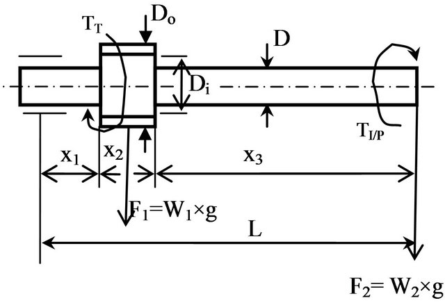
Figure 4. Input shaft design model.
| B.M.D |

Figure 5. Bending moment and shear force diagrams.
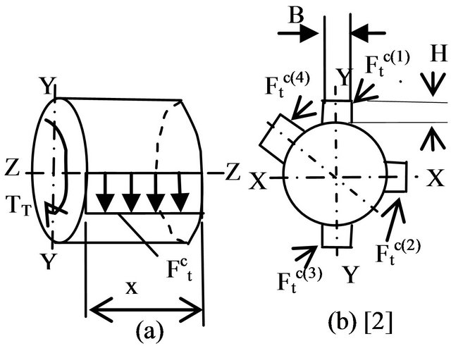
Figure 6. Diagram of contact forces caused by torsion.
invariants relative to tooth position (see Figures 6(b) and 7).
The bending and shear stresses value changes with the distance from neutral axis are shown in Figures 8 and 9.
Since the stressed state of any spline tooth under torsion is the same, dangerous stress combinations for any
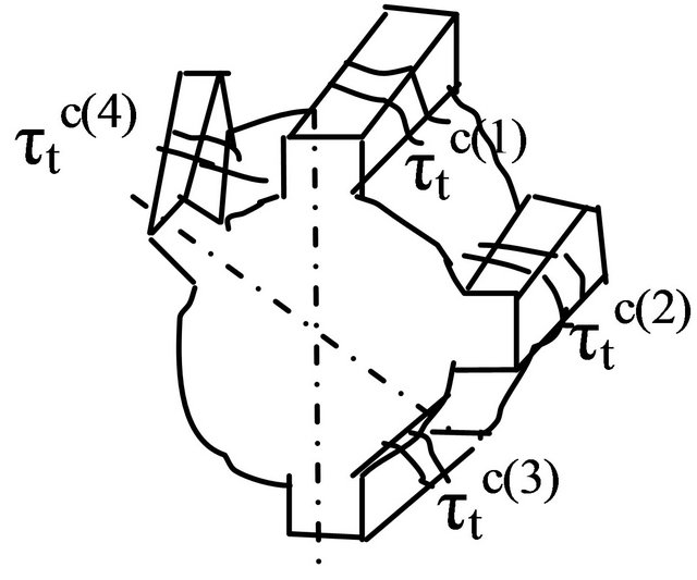
Figure 7. Torsional moment diagram [5].
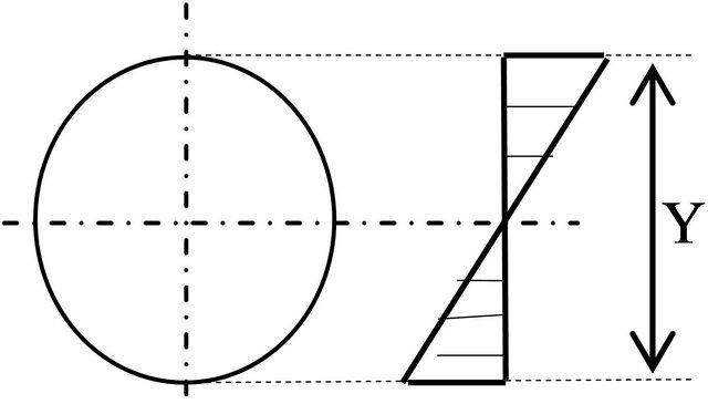
Figure 8. Bending stress diagram.
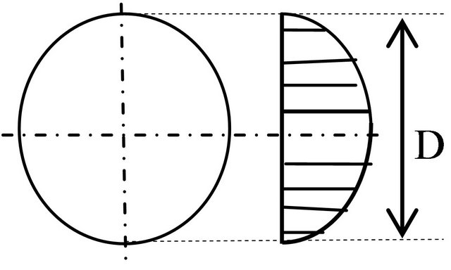
Figure 9. Shearing stress diagram.
tooth will be defined by bending. In the general case (torsion plus bending), the engineer should consider the spline tooth in three positions with different stress combinations (see Figure 10). In each of these positions, the engineer should analyze the possibility of appearance of three types of cracks shown in Figure 11: 1) transverse, 2) inclined, 3) longitudinal.
3. Torsion Stress
3.1. Spline Part Stress (Inclined Crack)
The Model of longitudinally mounted four speed automotive automatic transmission input shaft has spline part. This part is transmitting the torque converter turbine torque to the first planetary transmission gear set through its carrier. A stress analysis was first performed related to the torque converter size Equation (1) which can cause crack number (2) Figure 11 [5]:
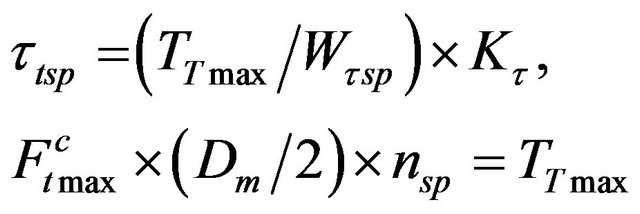 (1)
(1)
Wτsp= Polar moment of inertia (J) over distance of stress point from the neutral layer (y).
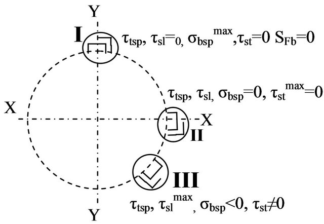
Figure 10. Three critical positions with different stress combinations of spline tooth [5].
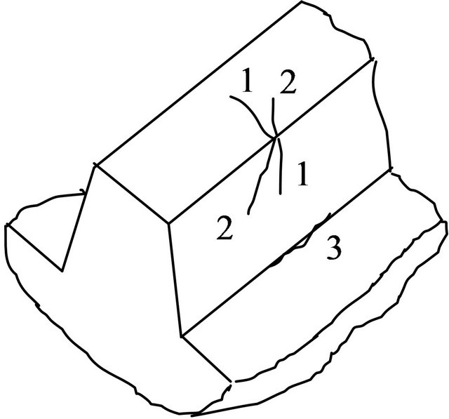
Figure 11. Three possible types of tooth cracks [5].

3.2. Solid Part Stress (Inclined Crack)
The same stress analysis (Equation (2) and Figure 12) is performed for the solid part of the input shaft which has different dimension. This difference is appearing into torsional section modulus (Wτsl) and the applied force value (Ft).
 (2)
(2)
4. Shear Stress
4.1. Spline Part Stress
4.1.1. Longitudinal Crack
In practice, when the spline tooth of the input shaft is loaded by twist force, the shearing force at a section always parallel to the tangential force (circumference force or contact force from torsion), . The resultant shearing stress at section [Equation (3)] assumes much importance in check the longitudinal input shaft crack

Figure 12. Torsional stress of solid shaft.
number (3) Figure 11.
 (3)
(3)
4.1.2. Transverse Crack
Also, there is direct shearing force Figure 5 at a section parallel to the perpendicular force which coming from the turbine weight (W1) and the planetary set (W2). The resultant direct shearing stress [Equation (4)] Figure 9 at section assumes much importance in check the transverse input shaft crack number (1) Figure 11.
 (4)
(4)
4.2. Solid Part Stress
The solid part of the transmission input shaft is affected by direct shearing force resulting from the planetary gear set weight (W2). Equation (5) shows the solid shearing stress which is suitable to the perpendicular crack of (Z-Z) direction Figure 12.
 (5)
(5)
5. Bending Stress
5.1. Spline Part Stress
The level of the bending stress [Equation (6)] through the spline part of the input shaft is measured by two forces F1 and F2 which are resulted from two weights W1 and W2 multiply by their distances starting from the forces applied points to the input shaft bearing support point (at the left point of the shaft). Also, the value of the modulus of shaft section effects on the stress [5].
 (6)
(6)
5.2. Solid Part Stress
The bending stress [Equation (7)] through the solid part of the shaft slightly different from the spline part where forces distances and modulus of section values are not the same.
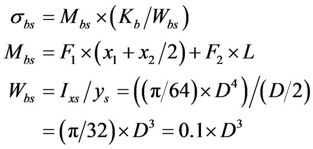 (7)
(7)
6. Compound Stress
The reliable study of power transmitting shafts stress sources and critical stress combinations are supported on three steps of study. First; torsion stress characteristics were studied for the given shaft for its different cross sections. Second; shear stresses also for the different cross sections were calculated. Third; bending stresses were established. Finally; compound stresses into the spline and solid parts were defined by Equations (8)-(11). Equations (8) and (10) are represented compound torsion stresses while Equations (9) and (11) are showed compound bending stresses [5].
Spline Part Stress
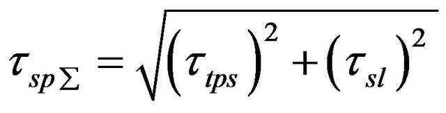 (8)
(8)
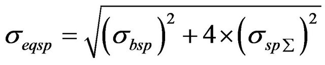 (9)
(9)
Solid Part Stress
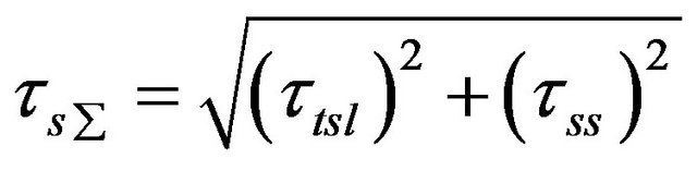 (10)
(10)
 (11)
(11)
7. Conclusions
1) The input shaft models were established having two different shapes of cross sections. Firstly; a circular cross section has splines around it. The splines are loaded by the torque converter turbine tortional force and weight. Secondly; a circular cross section hasn’t spline. It is loaded by the first planetary gear set weight and gear set torional force.
2) A combined action of compound torsion and bending has been considered in studying the stressed-strained state of splined and solid parts of the input shaft.
3) Generally, there are three critical of forces for the spline part tooth. For each the three forces, three types of cracks, transverse, vertical, and longitudinal, may be occurred.
Also, the above three forces affect on the solid part of the input shaft. They are causing three cracks, axially, vertically and transversally [6].
REFERENCES
- H. Heisler, “Advanced Vehicle Technology,” 2nd Edition, 2002, pp. 117-123. doi:10.1016/B978-075065131-8/50006-3
- P. M. Heldt, “Torque Converters or Transmissions,” 5th Edition, 1955, pp. 272-277.
- E. O. A. Abd Elmaksoud, E. M. Rabeih, N. A. AbdelHalim and S. M. El Demerdash, “Investigation of Self Excited Torsional Vibrations for Different Configurations of Automotive Automatic Transmission Systems during the Engagement Period,” Ain Shams Journal of Mechanical Engineering (ASJME), Vol. 2 No. 1, 2010, ISSN: 1687-8612,
- Y. Zhang and X. Chen, “Dynamic Modeling and Simulation of a Dual-Clutch Automated Lay-Shaft Transmission,” Journal of Mechanical Design, Vol. 127, No. 2, 2005, pp. 302-207.
- B. P. Volfson, “Stress Sources and Critical Stress Combinations for Splined Shaft,” Journal of Mechanical Design, Vol. 104, No. 3, 1982, pp. 551-556. doi:10.1115/1.3256385
- J.-D. Wu and J.-H. Lin, “Experimental Investigation of Active Vibration Control for Gear Set Shaft,” International Journal of Vehicle Noise and Vibration, Vol. 2, No. 1, 2006, pp. 1-16. doi:10.1504/IJVNV.2006.008523
Nomenclature
E Engine LU Locking clutch ODB, 2GB, (L + R)B Brakes OWC One Way Clutch DC, (H + R)C, FC Clutches P1, P2, P3 Planetary gears S1, S2, S3 Sun gears R1, R2, R3 Ring gears C1, C2, C3 Carriers M1, M2, M3 Moments A Action R Reaction D Input shaft diameter L Input shaft length W1 Turbine weight W2 Planetary set1 weight F1, F2 Normal forces G Acceleration of gravity U The velocity of the part on which the jet acts
ωup The tangential component of the relative velocity to the exit fluid of the impeller.
ωut The tangential component of the relative flow velocity to the exit fluid of the runner.
ωur The tangential component of the relative flow velocity to the exit fluid of the reactor (stator).
ωT Angular velocity of the turbine.
ωP Angular velocity of the pump.
ωE Angular velocity of the engine.
N The ratio of turbine (runner) to pump (impeller) speeds (rpm).
RT Turbine over pump torques ratio.
Rt Radius of the exit fluid from the runner.
RP Radius of the exit fluid from the reactor.
TT Turbine torque.
TTmax Maximum turbine torque.
TP Pump torque.
TE Engine torque.
TI/P Designed resistant torque of the planetary gear set.
iDC Planetary set reduction ratio with DC clutch.
iODB Planetary set reduction ratio with ODB brake.
SF Safety Factor.
 Contact force from torsion
 Torsional moment.
Ʈtsp Torsional stress through the spline part.
Ʈtsl Torsional stress through the solid part.
Ʈsl Longitudinal shear stress through the spline part.
Ʈst Transverse shear stress through the spline part.
Ʈss Shear stress through the solid part.
Ʈsp∑ Compound torsional stress of spline part.
Ʈs∑ Compound torsional stress of solid part.
Ϭeqsp Compound bending stress of spline part.
Ϭeqs Compound bending stress of solid part.
Fs Shear force.
Ft Tangintial force from torsional.
Wτsp Torsional section modulus of the shaft spline part.
Wτsl Torsional section modulus of the shaft solid part.
Wbsp Bending section modulus of the shaft spline part.
Wbs Bending section modulus of the shaft solid part.
Kτ Stress safety factor.
Do Outer diameter of the shaft spline part.
Dm Mean diameter of the shaft spline part.
Di Inner diameter of the shaft spline part.
D Diameter of the shaft solid part.
Ϭbsp Bending stress through the spline part.
Ϭbs Bending stress through the solid part.
Mbsp Bending moment through the spline part.
Mbs Bending moment through the solid part.
nsp Number of splines.
IX Moment of inertia around X axis IY Moment of inertia around Y axis Ixsp Moment of inertia around X axis of spline part.
ys Distance from the section axis to the stress layer.
B Width of spline tooth (m)
H Height of spline tooth (m)
X1, X2, X3, L Distances (m)