Open Journal of Biophysics
Vol.3 No.1A(2013), Article ID:28294,10 pages DOI:10.4236/ojbiphy.2013.31A010
Error Corrected Sub-Monolayer Ellipsometry for Measurement of Biomolecular Interactions
DRE-Dr. Riss Ellipsometerbau GmbH, Ratzeburg, Germany
Email: dr.riss@dre.de
Received December 25, 2012; revised January 26, 2013; accepted February 4, 2013
Keywords: Ellipsometry; Ellipsometer; Antibody; Antigen; Virus; Membrane; Kinetics; Electrodynamics
ABSTRACT
Already in 1946 Alexandre Rothen from the Rockefeller Institute for Medical Research, New York published the use of ellipsometry for the measurement of antigen-antibody interactions. And he found some effects that could not be explained by the assumption that the interaction of the molecules is only of chemical nature. 55 years later we started research on antibody-antigen interaction and found similar results. To make sure that these measurements are not produced by measurement artifacts, each component of our measurement technique is error analyzed and error corrected if necessary. With such type of error corrected instrumentation we found, that there must be an interaction between antigens and antibodies that is based on longitudinal electromagnetic waves, which are able to work through thin 7 nm membranes. A similar interaction is found for the virus-antigen interaction. Our measurement results are in contrast to the assumption that the antigen-antibody and antigen-virus interaction is only of chemical nature.
1. Introduction
Ellipsometry is an old technique to measure thickness and refractive index of thin films starting at a contamination of a surface with some molecules and ending at some microns thickness. Different types of ellipsometers are known and described in the book “Ellipsometry and Polarized Light” [1]. Medical or biophysical applications often require extremely high sensitivity and small measurement errors, because the measured effects are very small. One biological application is for example the measurement of very thin antigen-antibody sub-monolayer. Alexandre Rothen [2] was the first who used ellipsometry for the measurement of immunological reactions between films of antigen and antibody molecules. He found that also antigens that have not the possibility to have direct contact to antibodies are attracting antibodies. And so he stated: “Great difficulty is therefore encountered in trying to explain such phenomena on the basis of the current chemical theories which axiomatically assume that the reaction occurs between definite groups of the antigen and definite groups of the antibody. If this were the case, how could definite groups of antibody molecule react with definite groups of an antigen film buried under seven layer of the same antigen, 56 Å deep?” But Alexandre Rothen had no explanation for that what he measured. And so his research was ignored by the scientific community. 55 years later we started research on antibody-antigen interactions with ellipsometry. For this research we used highly specific antibodies extracted from human serum and antigens produced in a rabbit [3]. And we found unexpected effects, too. An antibody that is coupled to a 40 nm gold particle acts as it is expected from the law of mass action, but if no gold particle is coupled to the antibody the antibody is ignoring the law of mass action and is moving significantly faster to the antigen. To make sure that the measured unexpected effect is not caused by a measurement artifact all components of the measurement system must be analyzed, error corrected and evaluated.
2. Principle of an Ellipsometer
An ellipsometer is an instrument to measure thin layers or the interaction of biological molecules. Linear or elliptical polarized light hits a sample. The sample changes the state of polarization of the reflected light. The reflected light is send through polarizing components and analyzed. Figure 1 shows the principle of a PCSA Null-ellipsometer (EL X-05 B III) and a Minsearch ellipsometer (EL X-02 B III) which can be used for measurement of biomolecule interactions. To get correct results the errors of all components must be analyzed and corrected. It follows an error discussion of all components of an ellipsometer. The task of the discussion is to make sure that found new biological
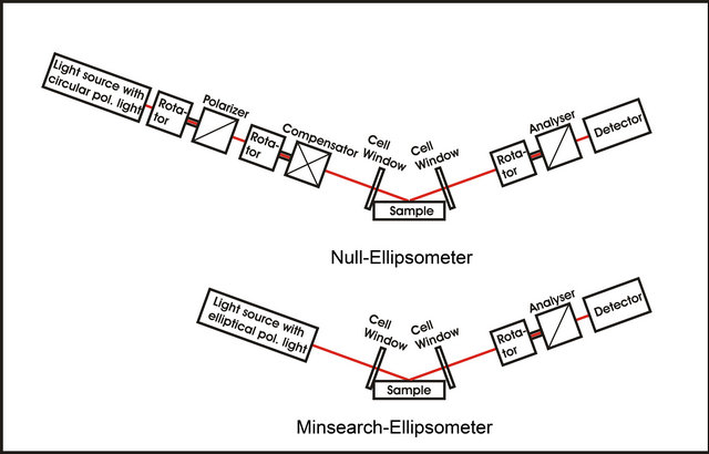
Figure 1. Principle of a Null and a Minsearch-Ellipsometer for measurement of very thin films.
effects really exist and are not caused by a measurement artifact.
2.1. Light Source of an Ellipsometer
For getting correct results at a single wavelength the usage of a laser makes sense. Laser diodes show a temperature dependence of the wavelength. So laser diodes need temperature stabilization to 0.001 K to avoid this effect. The anisotropy of a glass plate can be used for example as frequency discriminator. When using the electric current as frequency changing quantity it is possible to reach a frequency stability of about 50 MHz. The intensity instability of such laser diode is in the order of 0.1%.
A second possibility gives the usage of a gas laser. A HeNe gas laser has an amplification bandwidth of about 1.2 GHz. But such a laser shows mode running, which results in a permanent change of laser intensity. When using a laser with two modes the mode running stops about 1 hour after power on and both modes will have same frequency distance from the center of the gas amplification curve. Intensity stability is also in the order of 0.1%.
A further increase of frequency stabilization can be achieved if a laser with two orthogonal polarized modes is used. Mixing both modes with a polarizing prism and analyzing the signal with a photodiode gives the intermediate frequency which can be used as control variable for frequency stabilization. With such a control a frequency stabilization of better than 10 kHz can be achieved.
HeNe laser show a stable polarization that is defined by mirror anisotropy. To get circular or strong elliptical polarized light the usage of a quarter wave plate is necessary. An error discussion of the quarter wave plate is done in the chapter compensator.
2.2. Error Corrected Rotators
The ellipsometers shown in Figure 1 have rotators to rotate optical components. High angle resolution can be achieved if a mechanical gear is added to a step motor. But this concept has a big problem: Wear and tear. And this type of rotator has additional problems with hysteresis, slackness and systematic errors. For reduction of slackness the gear wheels must be prestressed, but this increases hysteresis. Hysteresis can be eliminated, if the last part of the rotator movement is always the same. In this case the rotator can be error corrected with an optical encoder to receive an angle precision of 0.001˚. Our first ellipsometer was equipped with this type of rotator, but we found that the precision can be hold only for a small time period. After one month of permanent use the systematic error increased to 0.01˚ and a new error correction was required. So we changed to another concept.
Instead of a mechanical gear we used a micro stepcontrolled step motor. Here we do not have wear and tear but a big hysteresis effect. The hysteresis effect can be eliminated, if the last part of the rotator movement is always the same, the history of movement must be the same. With this concept an angle reproducibility of better than 0.0005˚ can be achieved over long time period (several years). But similar to a mechanical gear this type of rotator has big systematic errors which must be corrected.
Error correction can be done with an optical angle encoder. A direct coupling of the angle encoder to the step motor is not possible; because the errors of a step motor are momentum-dependent.
The coupling of an angle encoder to the step motor produces a mechanical momentum which changes the error curve of the step motor. So we preferred an optical coupling of step motor and angle encoder which produces no additional mechanical momentum. The coupling itself is done by two polarizing prisms with extinction ratio of 10−7. Figure 2 shows the setup.
Typically micro step controlled step motors have static errors (after stop of movement) in the order between ±0.03˚ and ±0.1˚. Figure 3 show the errors for the prototype of step motor with errors in the order of ±0.05˚. With error correction these errors were reduced to rest errors between −0.003˚ and +0.002˚.
For error correction it is not necessary to measure errors at 360,000 different angle positions. A reduction to 7200 different positions gives also very good results. In this case the errors can be corrected by use of 7200 linear regression curves. So before rotating to an angle position a computer makes an error correction. With the optical coupling to the optical encoder it can be validated whether the error correction works or not.
While doing this we found the effect that error correction is correct if we have the same optical coupling direction, but is not correct, if the orientation of coupling is rotated by 180˚. In this case we had a systematic sine error with 0.00175˚ amplitude. This error was produced by the eccentric mounting of glass parts in the optical encoder. A field test of the producer of the encoder showed, that each encoder has a similar error effect.
Angle encoders with coupling errors <0.001˚ have dimensions that are too big for use in this application. So we added a second error correction for correction of coupling errors of the angle encoder.
The 7200 linear regression curves for error correction are modified so that this type of error is also taken into account. This type of error correction gives rotators with very high precision. After 21 years of use the residual errors of the error corrected step motor (prototype) increased by less than 0.001˚. Also heating of the step motor had no significant error effect. Compared to our prototype our current error corrected step motors have become smaller and more precise. With our current techniques micro step controlled step motors can be used as long term stable rotators with ±0.002˚ precision. They have only a dimension of 38 mm × 38 mm × 45 mm. In principle accuracy of step motors can be increased to 0.0001˚, here we see a technical border for such small step motors.
2.3. Polarizer/Analyzer
In ellipsometry polarizers are used to create linear polarized light on light source side and as analyzer.
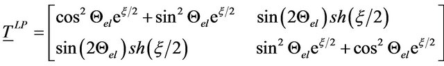
The Jones Matrix TLP [4] of an ideal polarizer can be described by (see Equation (1)):
with:
 : Orientation of eigenpolarization el;
 : Absorption related component (describes extincttion ratio).
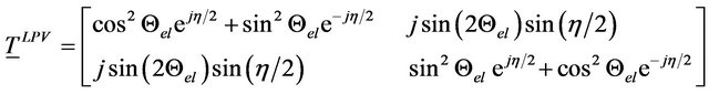
In reality a polarizer cannot be interpreted as ideal polarizer with linear eigenpolarisations it must be interpreted as elliptical polarizer with elliptical eigenpolarisations. The Jones Matrix TLPV [4] can now be described by: (see Equation (2)).
With:  (Δ: retardation).
When doing an error correction of a polarizer the retardation must be analyzed and taken into account. Even when using Glan-Thompson polarizers with extinction ratios of 1:10−7 the retardation effect is not negligible small. Such a polarizer can produce an ellipticity of a
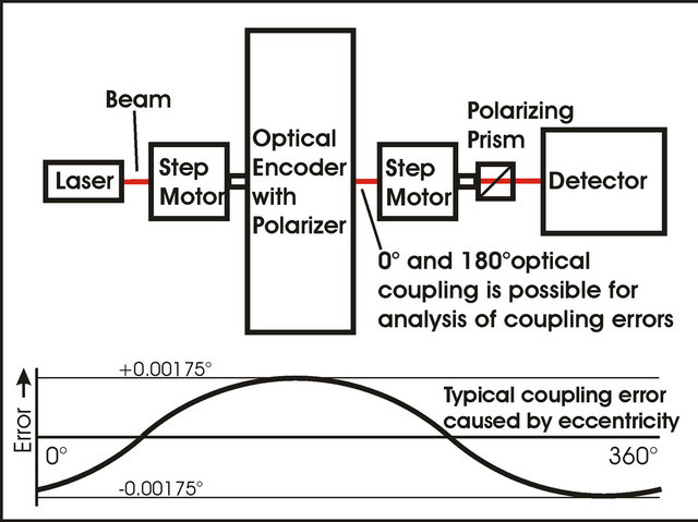
Figure 2. Error correction system for micro step controlled step motors and sine error curve of the angle encoder.
 (1)
(1)
 (2)
(2)
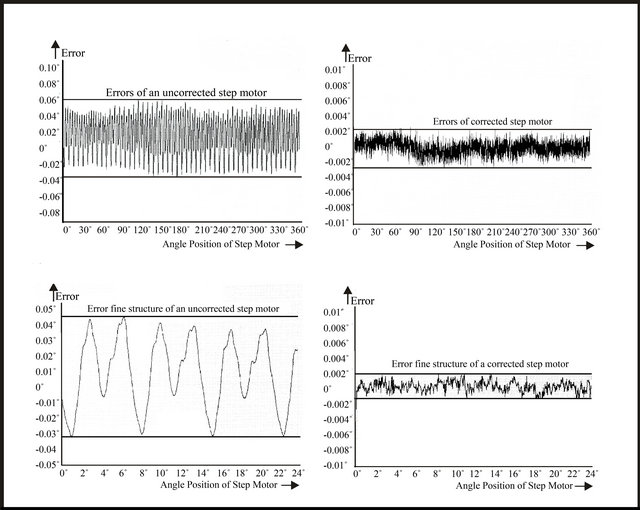
Figure 3. Error curves of an uncorrected and a corrected step motor.
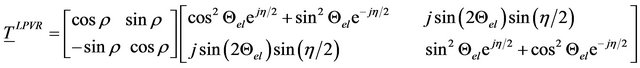
passing electromagnetic wave of 0.018˚ which corresponds with a Δ-error of the polarizer of about 0.036˚. To avoid such type of Δ-errors of the polarizer the Δ-effect must be analyzed and taken into account. This can be done for example with a transmission ellipsometer [5] or other measurement methods. Δ-anisotropy of a real polarizer is normally brought via photoelasticity into a polarizer. If the orientation of the mechanical stress in the polarizer rotates in beam direction an additional rotation ρ of the exiting beam can be observed. The Jones Matrix of such a polarizer TLPVR [4] can now be described by (See Equation (3)).
We defined  as pseudoactivity angle. This angle acts like optical activity but in contrast to optical activity this rotation is of reciprocal nature. That means a rotated beam would be rotated back after reflection (optical activity would lead to further rotation).
2.4. Compensators
Several types of ellipsometers have compensators. Compensators are normally made of quarter wave plates. Producers of quarter wave plates differ normally between zero order and multi order plates. Zero order means that the retardation Δ is a quarter of the wavelength λ (Δ = λ/4), multi order means that a number of complete wavelengths have to be added to the retardation of the plate (Δ = λ/4 + nλ, n = 1, 2, 3, 4 …). Quarter wave plates have two interfaces between plate and ambient medium which is normally air. With these two interfaces the quarter wave plate works like an anisotropic Fabry-Perot resonator. Figure 4 shows the block diagram of the plate.
with: (see Equation (4))
xy: 01, 11, 13, 21,12, 20, 22 or 31;
txy: absorption;
δxy: phase shift;
φxy: orientation of anisotropy;
ρxy: pseudoactivity angle;
Δxy: retardation;
Ψxy: anisotropic absorption.
A change of temperature results in a change of δxy (δ11
and δ22) in the Jones Matrices  and
and  (Figure 4).
The δxy change is caused by temperature dependent expansion. In combination with the interfaces becomes
 (3)
(3)
 (4)
(4)
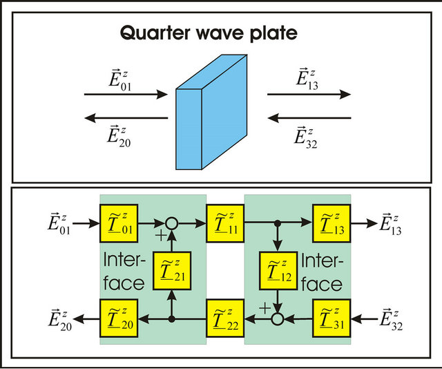
Figure 4. Blockdiagram of a quarter wave plate.
the anisotropy of the plate temperature dependent. This temperature dependence is for a multi-order plate higher than for a zero order plate. A reduction of the temperature dependence can be reached by a very good anti-reflection coating of the plate. For the amplitude of the anisotropy change  we get:
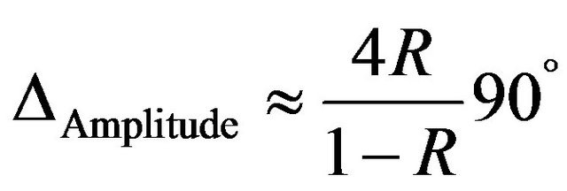 (5)
(5)
with:
R: reflectivity (intensity related) of the antireflection coating.
For elimination of this effect ( ), the anti reflection coating must have a (intensity related) rest reflectivity of less than 0.00028%, which is not possible. So a long temperature periodicity and very good temperature stabilization is required. For the temperature periodicity TPeriod we get:
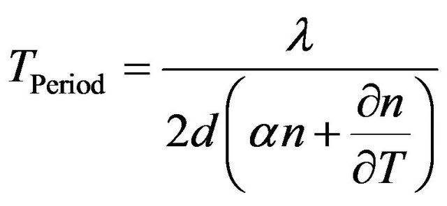 (6)
(6)
with:
λ: wavelength;
d: thickness;
α: thermal coefficient of expansion;
 : thermal coefficient of refractive index;
T: temperature.
It can be clearly seen that anti-reflection coating and temperature stabilizing have a positive effect on the long term stability of a quarter wave plate. Achromatic quarter wave plates which are used in spectroscopic ellipsometers have not so good anti-reflection coatings as zero order quarter wave plates which are used in single wavelength instruments. Additional to this the errors of achromatic quarter wave plates are so big that there is a must of an error correction of the retardation. Additional to this we measured that even high quality quarter wave plates can have pseudoactivity angles ρ in the order of up to 3˚ which produces a corresponding rotation of the reference plane of the ellipsometer after the quarter wave plate. The pseudoactivity angle ρ of a quarter wave plate is wavelength dependent and so this error must be corrected for each wavelength separately. We use compensators with error correction only in our null ellipsometers (for example: EL X-05 B III) where a compensator is required. Our ellipsometers that are using the Minsearch Algorithms (for example: EL X-02 B III) do not have a compensator. This has the advantage that compensator errors cannot influence the result, but the disadvantage that the instrument cannot differ between right handed and left handed polarization; but for thin film measurement the differentiation between right handed and left handed polarization is not required. In high precision ellipsometers some times compensators are used after the analyzer to provide the detector with circular polarized light to correct polarization effects of the detector. If the detector shows only small polarization dependence it is better to make a mathematical correction. Our ellipsometer always use a mathematical correction of detector anisotropy.
2.5. Cell Windows
In-situ measurements of the binning kinetics of antibodyantigen interactions require cells with entrance and exit windows. But these cell windows show anisotropy. For error correction the four ellipsometric quantities Δ, Ψ, φ and ρ must be measured for each window and later used for cell window correction [4,5]. Δ-anisotropy of cell windows can be in the order between 0.01˚ and 1˚ and is not negligible small.
2.6. Detector
A silicon diode has a linearity error of 10−7 or less. The following transimpedance that makes a current voltage transfer must have high linearity. For static application as Null-Ellipsometry or Minsearch Ellipsometry this is normally no problem. In dynamic applications the bandwidth of the transimpedance must be very high to avoid systematic errors.
3. Calibration of the Instrument
Often calibration standards are used for calibration of an ellipsometer. Certified SiO2-standards are available from 2 nm to 1010 nm. When looking at a bigger number of calibration standards we found that some of these standards are certified with a slightly different refractive index for the SiO2 coating even if all calibration standards are produced with the same coating process. From our point of view it makes no sense that the refractive index of a SiO2 layer changes only for a definite layer thickness. Measuring with our technology we found the same refractive index for all calibration standards, which is from our point of view more plausible.
If you remove the SiO2 layer of a native silicon sample with HF-acid you can see the oxidation afterwards in air in-situ with an ellipsometer. After 1 hour the sample shows a layer thickness of 0.7 nm. But this oxidation does not stop at 0.7 nm. The oxidation continues and we do not think that the oxidation stops at 2 nm. In a production line a 400 nm calibration standard was used as reference. After several years this standard showed a thickness which was significantly (10%) higher than specified. So we think that the ellipsometer precision can be checked with a young calibration standard, but it should not be used for calibration of the instrument. If you use a correct defined calibration standard (for example 20 nm) for calibration of the instrument, you will get later correct results if you are measuring SiO2/Si-samples that have thicknesses in the range 18 - 22 nm. If you are measuring samples in another thickness range or if you measuring a coating with different refractive index you cannot be sure that you are getting correct results.
So we think that a calibration to absolute physical quantities (as we do) is better than a calibration with a SiO2 standard. A young calibration standard can then be used for control of the instrument calibration which is done to absolute quantities.
4. Measuring Biomolecular Interactions
After error correction of each component the user can be sure that the ellipsometer is measuring correctly. But the sample must also be prepared correctly, too. So the sample preparation should not have not exactly known coatings. If antigens are coated to a surface, these antigens must be produced in a definite process to avoid measurement artifacts. For getting a defined sample system we removed the SiO2 surface of a native silicon sample with HF-acid. Then direct after cleaning, the sample was dipped for some seconds into a solution with antigens. The antigen-coated silicon sample was put into the cell and the kinetics of antibody binning was measured. With this type of sample preparation we measured for goldlabeled antibodies a binning kinetics as expected from the law of mass action and a kinetics of unlabeled antibodies that stands in contrast to the law of mass action [3]. We developed the theory that antibodies are able to detect antigens over a long distance via longitudinal electromagnetic waves. This theory was published in a simplified form [3] and is consistent with the measurements made by Alexandre Rothen [2].
According to Maxwell’s equations [6]:
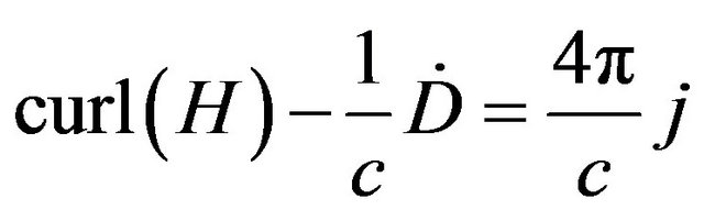 (7)
(7)
 (8)
(8)
we see that a transversal electromagnetic wave (represented by E and H) is orthogonal to the change of electric displacement D und electric current density j. An oscillating NH3+-charge of an antibody produces a transversal electromagnetic wave (Hertzian dipole) and orthogonal to this a longitudinal wave (represented by the change of electric displacement D and electric current density j). The required energy supply for the longitudinal wave comes from Brownian movement of particles that hit the antibody arm [3]. Antigens are supplied with energy by a similar process; they are also producing longitudinal electromagnetic wave.
We have found several biological effects that are explainable with our “Theory of long distance interaction between antibodies and antigens” [3] and have made some forecasts:
1) ScFv single chain antibodies can only work, if both chains are connected by a linker of definite size. According to our theory the linker must compensate the mass of the constant antibody region and elasticity of the hinge region of the high affinity full sized antibody, from which the chains are taken;
2) Bispecific antibodies will not work with high affinity, if left and right arms of the antibody are taken from different high affinity full sized antibodies;
3) Bispecific antibodies will work, if left and right arms are identical, but the light and heavy chains are taken from different high affinity antibodies. But these antibodies will have a 10 fold reduced affinity [7];
4) High specific antibodies can detect antigens through a 7 nm Si3N4-membrane, that has no permeability for gases;
5) Antibodies produced with help of phage display are polyspecific [8];
6) After infection the first produced antibodies are polyspecific [9];
7) A virus is moving extremely fast and directly to antigens;
8) FAB-fragments taken from a high affinity antibody show a low affinity compared to a full sized antibody (outstanding prove).
Discussing our experiments and forecasts with immunologists intensively we were told that our experiments are nice and trustful but that a theoretical physical model as we have developed [3] and the mathematics behind it has no significance to immunology because immunology is based on bench work and not on mathematics and physical models. We should do further experiments based on classical immunological methods, which can be evaluated by immunologists. But independent of this discussion the forecasts 1 - 7 from our theory (see 1 to 7 above) are accepted by some leading immunologists, because most of them can also be validated with classical immunological methods. But immunologists also say that there can be an interpretation different from ours for the forecasted and seen effects. But if we can show with classical immunological methods that forecast no. 8 is correct this would lead to a change of paradigms in immunology.
It is known that IgM-antibodies have significantly higher affinity as their FAB-fragments [10,11] which fulfill our forecast no. 8. This can be seen as first hint, that our forecast no. 8 is correct, but immunologists have a different explanation for this effect, they say that the dissociation rate of complete antibodies is smaller because the number of the FAB-arms is higher. We say that the dissociation rate can only be reduced by a factor between 2 and 5 if the number of arms would be the reason and the better mobility of FAB fragment would compensate this effect partly. For high affinity antibodies the dissociation must be very small. With our ellipsometer experiments we always found a stable layer with no dissociation if we worked with unlabeled high affinity antibodies and very high antigen concentration. In an experiment with high affinity viruses we found that all viruses moved to their antigens within 1 second (20 µl cell was used).
In a discussion with developers of antibodies [12] one of them told us, that he works with the model that an antibody has an uncertainty in position in the order of 1 micron or more. Only such a model can explain the chemical interaction of antibodies and antigens. This model is the chemical pendant of our wave model. But we do not think that a molecule that has only a size of some nanometers can have uncertainty of microns and we also think that the required energy for an extreme fast movement in a 1 micron sphere is enormous. The theoretical model we have developed implies an electrodynamic sphere of more than 1 micron. This model does not require this tremendous energy supply.
We are currently working on further validation of forecast no. 8. And we must do some other experiments for example membrane experiments, which cannot be explained by chemical effects.
5. Membrane Experiments
Very interesting are thin membrane experiments (thickness of membrane <10 nm). Figure 5 shows a possible production process of such a membrane. The membrane can be used as border to make sure that there cannot be a chemical interaction between antibody and antigen. According to our “Theory of long distance interaction between antibodies and antigens” [3] there must be a measurable binning of antibodies to the membrane if antigens are on the other side of the membrane (Figure 6). In principle this experiment is compatible with the experiment Alexandre Rothen [2] has done. But now we are absolutely sure that there cannot be a chemical interaction between antibodies and antigens. The membranes
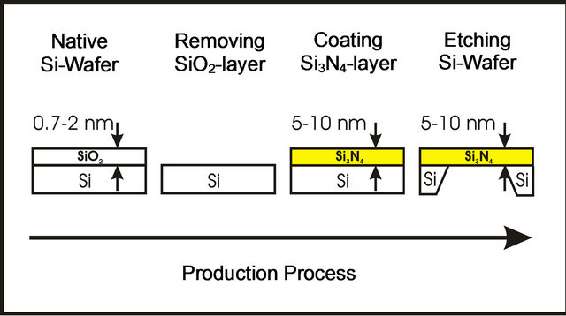
Figure 5. Possible production process of a 5 - 10 nm membrane.

Figure 6. Binning of antibodies to a membrane if antigens are on the other side of the membrane.
we are using were originally designed for transmission electron microscopic (TEM) measurements. Similar membranes are also commercial available [13] and used in TEM application to measure biological molecules in natural form. These membranes can be only used in TEM applications if they are not permeable for water, gas, and small biological molecules.
Figures 7 and 8 show simulation diagrams (thickness and sensitivity) of antibody binning to a membrane.
An error correction to instrument rest errors (Δ-errors) of 0.004˚ makes an absolute precision of 0.014 nm possible. This is sufficient for membrane experiments. Without error correction of ellipsometer rotators precision would be in the range of 1.8 nm.
6. Outlook
We think that there is not only a non-chemical interaction between antibodies and antigens; we think a lot of other “biochemical” interactions are based on electrodynamics. At the moment we are developing a theory on an elec-
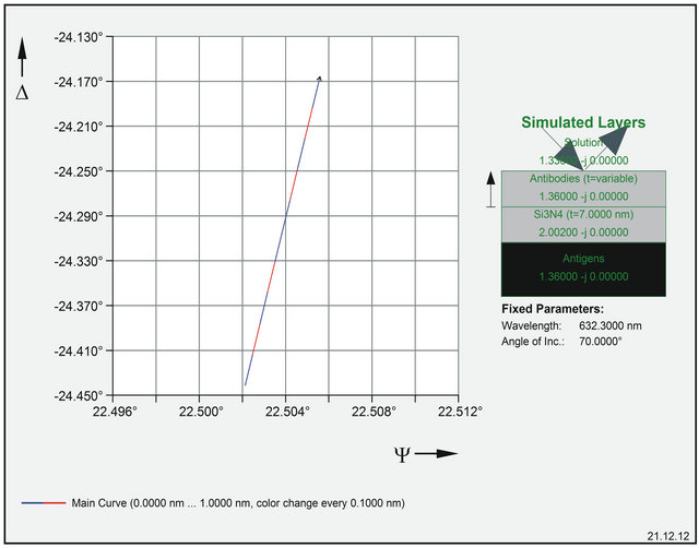
Figure 7. Simulation of antibody binning to a 7 nm Si3N4-Membrane (taken from EL X-02 BIII simulation software).
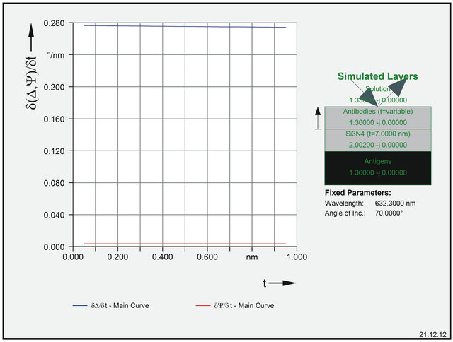
Figure 8. Simulation of and ∆ and Ψ-sensitivity (taken from EL X-02 BIII simulation software).
trodynamic information transfer between antibodies and cells with help of messenger molecules. We think that this information transfer is necessary to explanation the principle of somatic mutation of antibody production. The cells that are producing antibodies must have a feed back on the affinity of the currently produced antibodies. Only this feed back to the cells makes it possible to optimize affinity of the produced antibodies. A stochastic chemical feedback is too slow and too unsure for control of somatic mutation. Longitudinal terahertz signals enable a stable communication, but the absorption of a longitudinal terahertz wave in water is too high for direct communication between antibody and cell. So messenger molecules which are located between antibody and cell are required for an electrodynamic signal transfer. According to our theory these messenger molecules must be switched on and off to transfer information. We have found a theoretical physical mechanism that can be used for this switching. To validate our theory we are developing at the moment a so-called nanostructure ellipsometer with lateral resolution beyond the diffraction limitation which is able to analyze the switching process of these messenger molecules. If the messenger molecules are switched on, a binning of other molecules (for example antibodies) to these molecules must be possible. If the messenger molecules are switched off no binning of antibody molecules must be possible. We are focusing at the moment on instrument development.
7. Conclusion
Ellipsometry is a powerful tool to analyze biomolecular interactions in a nondestructive way. After doing an error correction of ellipsometer components the measurement results are trustful. This gives the possibility to validate new biological effects.
REFERENCES
- R. M. A. Azzam, and N. M. Bashara, “Ellipsometry and Polarized Light,” Elsevier, Amsterdam.
- A. Rothen, “Immunological Reaction between Films of Antigen and Antibody Molecules,” JBC, 1946.
- U. Riss, “Theory of Long Distance Interaction between Antibodies and Antigens,” European Biophysics Journal, Vol. 40, No. 8, 2011, pp. 987-1005.
- U. Riss, “Zur Transmissionsellipsometrie Optisch Anisotroper Komponenten und Systeme,” Ph.D. Dissertation (Mechanical Engineering), University of Kassel, Kassel, 1988.
- U. Riss and W. Holzapfel, “Properties and Characteristics of Optical Glass,” SPIE Proceedings, Vol. 970, 1988, pp. 48-61.
- M. Born and E. Wolf, “Principle of Optics,” 6th Edition, 1986, p. 1.
- Y. Chen, “Generation and Affinity Maturation of Fully Human Soluble VH Domain Antibodies and IgGs Using dsDNA Display,” Bit’s 4th Annual Congress of Antibodies, Peking, 2012.
- U. Riss, “Theory of Long Distance Interaction between Antibodies and Antigens,” European Biophysics Journal, Vol. 40, No. 8, 2011, pp. 987-1005.
- U. Riss, “Theory and Measurement of Long Distance Interaction between Antibodies and Antigens,” Bit’s 4th Annual Congress of Antibodies, Peking, 2012.
- A. Schmiedl and S. Dübel, “Rekombinate Antikörper and Phagendisplay,” 2004. http://www.bbt.tu-bs.de/Biotech/SD/PDF/MolBioTech03Fin.pdf
- P. J. Hudson and A. A. Kortt, “High Avidity scFv Multimers; Diabodies and Triabodies,” Journal of Immunological Methods, Vol. 231, No. 1-2, 1999, pp. 177-189. doi:10.1016/S0022-1759(99)00157-X
- U. Riss, “Long Distance Interaction of Antibodies, Monoclonal Antibodies, Exploring Innovation in Therapeutic Antibody Development and Production,” London, 2012.
- TED Pella Inc., 2013. http://www.tedpella.com/grids_html/silicon-nitride.htm#_21500_10