Journal of Power and Energy Engineering
Vol.2 No.8(2014), Article ID:49283,14 pages
DOI:10.4236/jpee.2014.28006
Overview of Maximum Power Point Tracking Control Methods for PV Systems
Saleh Elkelani Babaa, Matthew Armstrong, Volker Pickert
School of Electrical & Electronic Engineering, Newcastle University, Newcastle, UK
Email: elkelani12@yahoo.com
Copyright © 2014 by authors and Scientific Research Publishing Inc.
This work is licensed under the Creative Commons Attribution International License (CC BY).
http://creativecommons.org/licenses/by/4.0/


Received 1 July 2014; revised 10 August 2014; accepted 27 August 2014
Abstract
Maximum power point tracking (MPPT) controllers play an important role in photovoltaic systems. They maximize the output power of a PV array for a given set of conditions. This paper presents an overview of the different MPPT techniques. Each technique is evaluated on its ability to detect multiple maxima, convergence speed, ease of implementation, efficiency over a wide output power range, and cost of implementation. The perturbation and observation (P & O), and incremental conductance (IC) algorithms are widely used techniques, with many variants and optimization techniques reported. For this reason, this paper evaluates the performance of these two common approaches from a dynamic and steady state perspective.
Keywords: Photovoltaic (PV) System, Boost Converter, Maximum Power Point Tracking (MPPT)

1. Introduction
Throughout the world, photovoltaic power generation is becoming increasingly popular due to a combination of factors: low maintenance, minimal wear and tear of components due to the absence of moving parts, lack of audible noise, absence of fuel cost, and pollution-free operation after installation [1] [2] . Small-scale PV installations are very popular as lighting and water pumping solutions in developing countries, remote villages, and small rural and urban communities. These systems are also commonly used in developed countries that have a considerable amount of solar irradiation [3] . As PV systems are required to be low-cost, compact in size, and operate as efficiently as possible, this paper focuses on maximum power point tracking control algorithms for standalone PV systems, with the aim of delivering optimum performance over the widest range of operating conditions possible. Since PV systems exhibit nonlinear behaviour, the maximum power point (MPP) varies with solar insolation, and there is a unique PV panel operating point at which the power output is at a maximum, as shown in Figure 1. Therefore, for maximum efficiency, it is necessary to use a maximum power point tracking (MPPT) algorithm to deliver optimal available PV output power at different operating points to the load. With this in mind, many maximum power point tracking algorithms have been developed, and much research has been carried out to optimize the various techniques [4] -[6] .
This paper provides an overview of the most common MPPT approaches. From this, it is found that the perturbation and observation (P & O) and incremental conductance (IC) algorithms are particularly popular approaches [5] . For this reason, this paper presents a simulation study comparing the relative performance of these two techniques with respect to dynamic and steady state performance, and hence overall system efficiency.
2. MPPT Techniques
Tracking the maximum power point (MPP) of a photovoltaic array is an essential stage of a PV system [7] [8] . As such, many MPPT methods have been introduced and numerous variants of each method have been proposed to overcome specific disadvantages. The large number of methods proposed can make it difficult to determine the best technique to adopt when implementing a PV system. The methods all vary in complexity, number of sensors required, digital or analogue implementation, convergence speed, tracking ability, and cost effectiveness. Furthermore, the type of application can have a significant impact on the selection of MPPT algorithm. For this reason, this paper summarises the most popular MPPT techniques in use today. Two promising methods are then highlighted for consideration when implementing a system which needs to cope well over a wide range of irradiance conditions.
2.1. Perturbation and Observation (P & O) Method
The P & O algorithm [5] [6] , as shown below in (Figure 2), operates by increasing or decreasing the array terminal voltage, or current, at regular intervals and then comparing the PV output power with that of the previous sample point. If the PV array operating voltage changes and power increases (dP/dV PV > 0), the control system adjusts the PV array operating point in that direction; otherwise the operating point is moved in the opposite direction [9] . At each perturbation point, the algorithm continues to operate in the same manner [10] [11] . The main advantage of this approach is the simplicity of the technique. Furthermore, previous knowledge of the PV panel characteristics is not required. In its simplest form, this method generally exhibits good performance provided the solar irradiation does not vary too quickly. At steady state, the operating point oscillates around the MPP voltage and usually fluctuates lightly. For this reason, the perturbation frequency should be low enough so
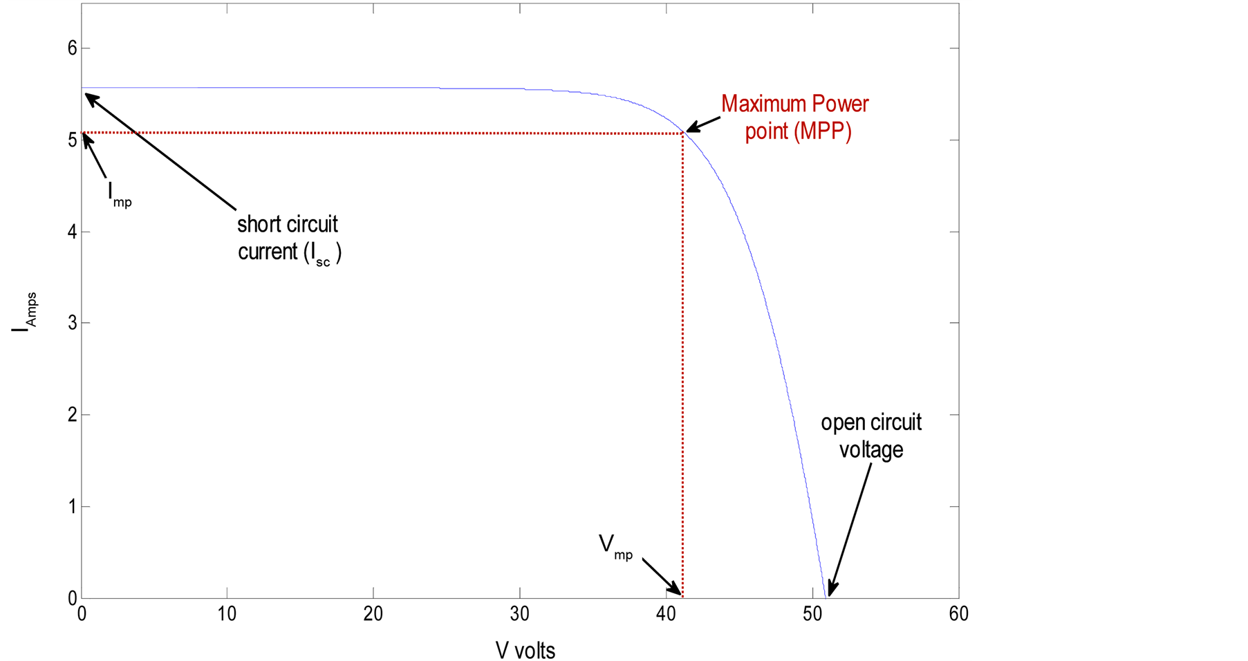
Figure 1. I-V characteristics of a typical PV panel with MPPT control.
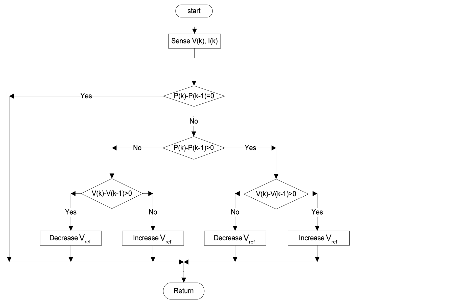
Figure 2. Flowchart of the P & O method.
that the system can reach steady state before the next perturbation. Also, the perturbation step size must be sufficient so that the controller is not significantly affected by measurement noise, and generates a measurable change in the photovoltaic array output [12] [13] .
The classic perturb and observe (P & O) method has the disadvantage of poor efficiency at low irradiation. For this reason, alternative solutions have been proposed. For example, Cristinel, Uffe, and Frede [14] combine a constant voltage (CV) algorithm with a modified P & O method as shown in (Figure 3) to track the MPP with high efficiency under both low and high solar irradiation conditions. The algorithm operates by increasing the duty cycle until the PV out put voltage is close to the open circuit voltage of the panel (VOC), this is then used as the initial conditions for the MPP tracker. The algorithm then evaluates the current output; if the current is higher than (0.7 A) the algorithm adopts the PO method; if it is lower it converts to the CV method. Simulation results demonstrate that overall greater energy can be extracted from the PV panel; efficiency levels of 95% to 99% are quoted over a wide irradiation range [14] . However, there is complication of combining the two methods.
The P & O method is also prone to erratic behaviour under rapidly variation in light levels. This may result in slow, or incorrect, MPP tracking. C. Liu, R. Cheung [15] , and A. Yafaoui, B. Wu [16] , introduced a modified P & O (MP & O) method to solve this problem. The method adds an irradiance-changing estimate process in every perturb process to measure the amount of power variation caused by the change of conditions. Results show improved performance over the conventional P & O method. However, MP & O has a slow tracking speed which is approximately half of the conventional P & O method. To improve the tracking speed of the MP & O method, an estimate, perturb and perturb (EPP) method is proposed by C. Lui, B. Wu, and R. Cheung [15] . The EPP algorithm uses one estimation step for every two perturbation steps [17] . It has been shown experimentally that, compared to MP & O, the EPP method has faster tracking speed, with a similar tracking accuracy to the MP & O algorithm [16] .
Ultimately, oscillations around the MPP give rise to loss of available energy [18] . To limit the impact of this issue, Nicola Femia [13] , show how the P & O parameters can be optimised for the dynamic behaviour of the specific power converter under investigation.
During rapidly changing irradiation, it is possible for the classic P & O algorithm to get confused and track the MPP in the wrong direction [5] [19] [20] . D. Sera, T. Kerekes, R. Teodorescu, and F. Blaabjerg [6] offer a

Table 1. Key data of the KD50SE-1P PV model and of the HIP-210NH1-BO-1, PV model
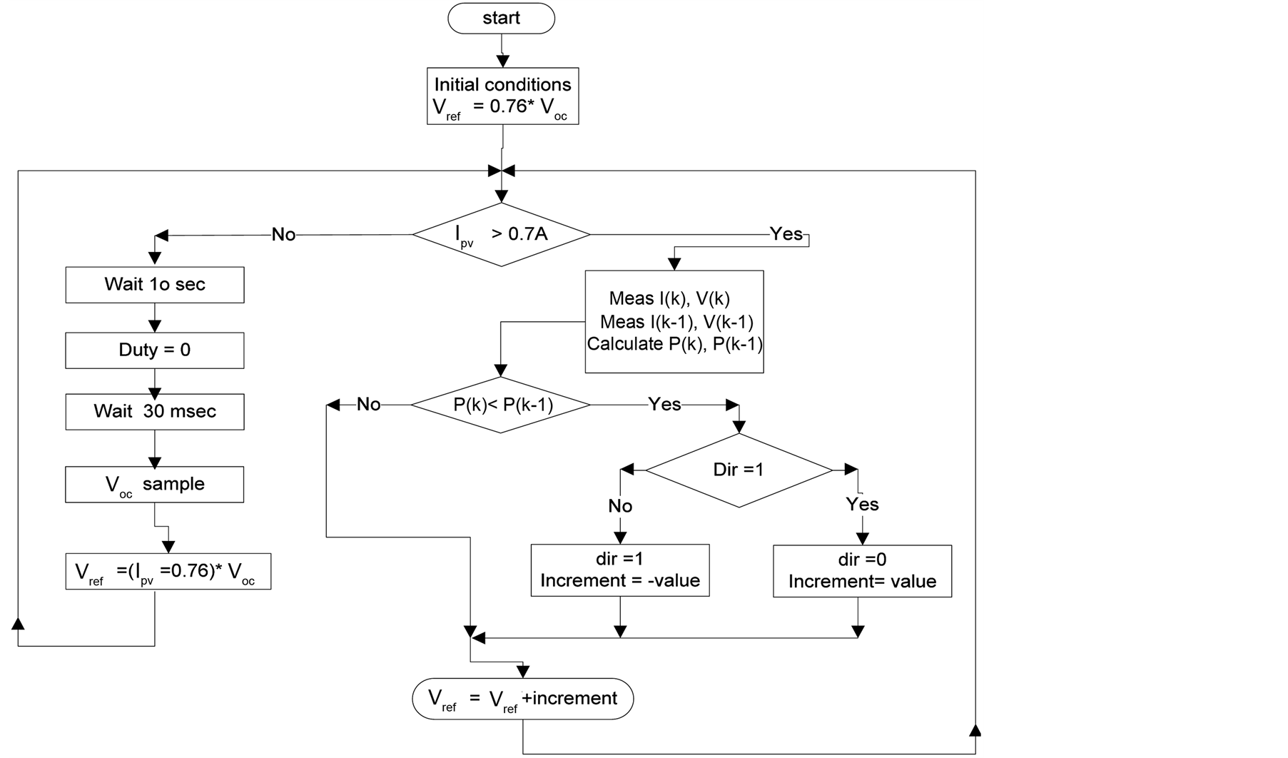
Figure 3. Flowchart of the combined P & O with CV.
simple and effective solution to this problem; dP-P & O. In this method, the power measurement is deconstructed to reveal the power coming from different sources. The MPPT is then provided exclusively with the power change created by its own previous instructions. To achieve this, an additional measurement of the solar arrays’ power is required. This is carried out at the mid-point of the MPPT sampling period as shown in (Figure 4). The method has been experimentally tested and compared with the classic P & O method. The results show that the dP-P & O technique is able to prevent the P & O from tracking in the wrong direction during rapidly changing irradiation, and considerably increases tracking speed.
2.2. Incremental Conductance (IC) Method
The incremental conductance (IC) algorithm which is shown in (Figure 5), seeks to overcome the limitations of the perturbation and observation algorithm by using the incremental conductance of the photovoltaic. This algorithm works by searching for the voltage operating point at which the conductance is equal to the incremental conductance. At this point, the system stops perturbing the operating point. The advantage of this algorithm is that it has the ability to ascertain the relative “distance” to the maximum power point (MPP), therefore it can determine when the MPP has been reached. Also, it is capable of tracking the MPP more precisely in highly variable weather conditions [14] , and exhibits less oscillatory behaviour around the MPP compared to the P & O method, even when the P & O method is optimized [19] . Nevertheless, the IC algorithm has the disadvantage that instability can result due to the use of a derivative operation in the algorithm. Also under low levels of insolation, the differentiation process difficult and prone to measurement noise; and results can be unsatisfactory [15] .
In general, the IC tracking approaches use a fixed iteration step size, which is determined by the accuracy and tracking speed requirement. The step size may be increased to improve tracking speed, however, accuracy is decreased. Likewise, reducing the step size improves the accuracy, but sacrifices the speed of convergence of the algorithm. To solve this problem, L. Jae Ho, B. Hyun Su, and C. Bo Hyung [21] proposed an IC technique with a variable step size. This approach automatically adjusts the step size to the solar array operating point. When the operating point is judged to be far from the MPP, the algorithm increases the step size to enable the algorithm to operating point of approach quickly towards the MPP. However, when the operating point is close to the MPP, the step size is decreased. Through the variation of the step size, both improved accuracy and speed are accomplished. Experimental results, based on a parallel buck converter system, validate the speed and ro-
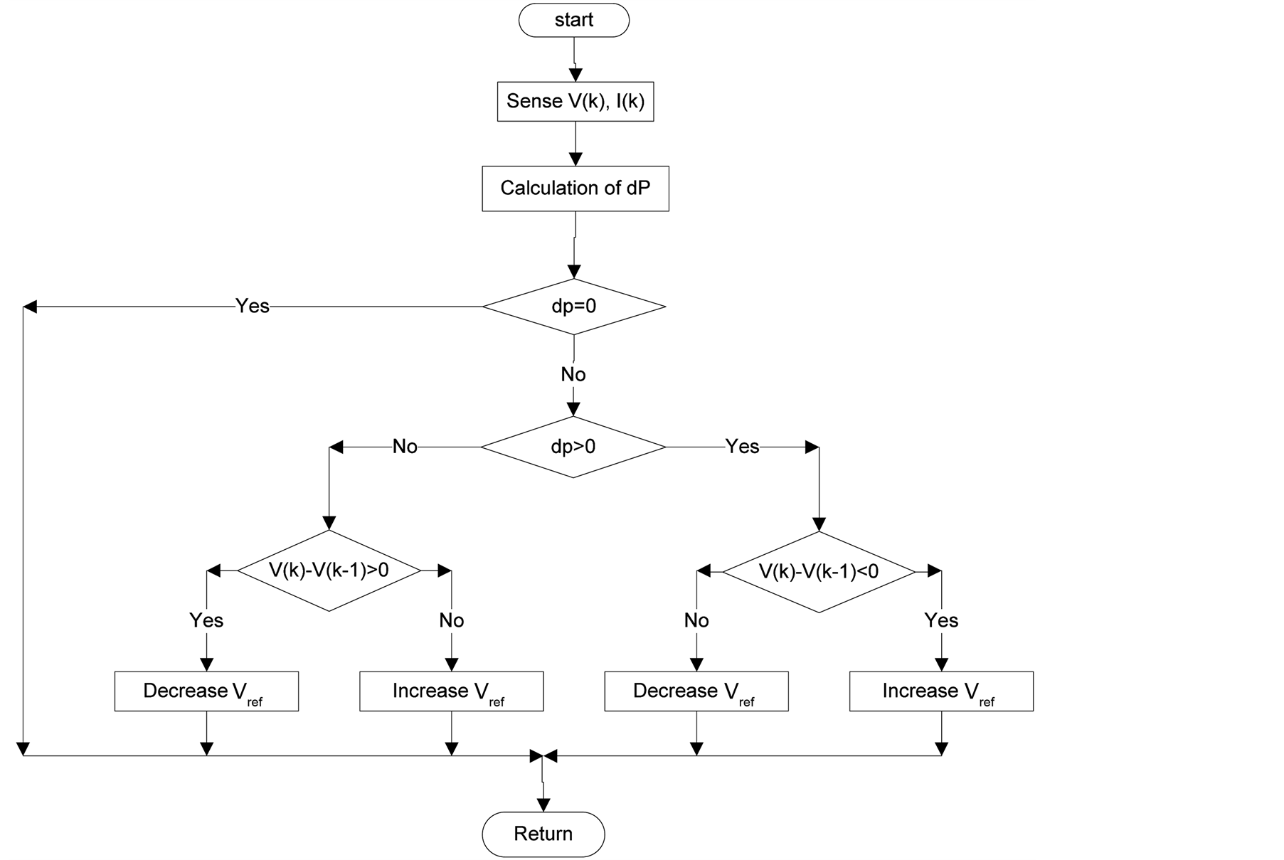
Figure 4. Flowchart of the dP-P & O method.
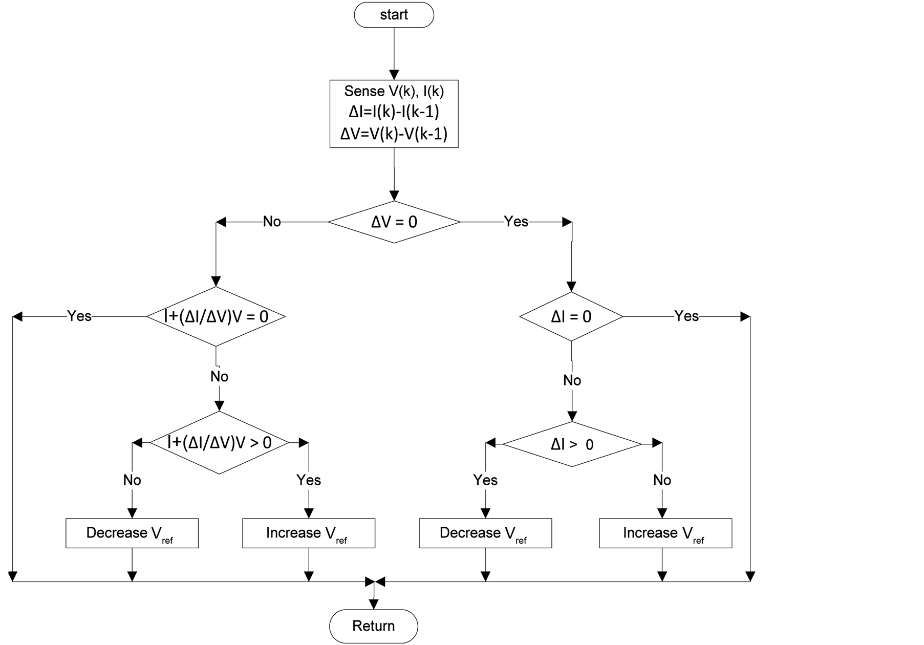
Figure 5. Flowchart of the IC method.
bustness of the scheme. Furthermore, small signal modelling, confirms the stability of the system in almost all cases [21] .
2.3. Constant Voltage (CV) Method
The constant voltage (CV) algorithm is one of the simplest MPPT algorithms. The
operating point of the photovoltaic array is retained near the maximum power point
(MPP) by regulating the solar output voltage to match an unmovable reference voltage . The reference voltage value is set equal to the
voltage at the maximum power point
. The reference voltage value is set equal to the
voltage at the maximum power point
 of the characteristic photovoltaic array. The algorithm assumes that PV panel variationssuch
as temperature and irradiation are not significant, and the constant reference voltage
is adequateto achieve performance close to the MPP. For this reason, in practice,
the CV algorithm may never exactly locate the MPP. During installation, it is usually
necessary to gather data to establish the constant voltage reference, as this may
change from one location to another. In low insolation conditions, it may be observed
that the constant voltage technique is more effective than either the perturb and
observe, or the incremental conductance algorithm [5]
[22] .
of the characteristic photovoltaic array. The algorithm assumes that PV panel variationssuch
as temperature and irradiation are not significant, and the constant reference voltage
is adequateto achieve performance close to the MPP. For this reason, in practice,
the CV algorithm may never exactly locate the MPP. During installation, it is usually
necessary to gather data to establish the constant voltage reference, as this may
change from one location to another. In low insolation conditions, it may be observed
that the constant voltage technique is more effective than either the perturb and
observe, or the incremental conductance algorithm [5]
[22] .
2.4. Temperature (T) Method
A temperature MPPT algorithm is introduced in papers from R. Faranda, S. Leva [5] and R. F. Coelho
[23] . By looking at the V-I characteristics,
it is observed that the short-circuit current
 of the solar array is proportional to the irradiance (G) level and is generally
steady when the cell temperature changes, whilst the opencircuit voltage
of the solar array is proportional to the irradiance (G) level and is generally
steady when the cell temperature changes, whilst the opencircuit voltage
 of solar panel is directly proportional to the PV array temperature
 . This algorithm employs temperature
sensors fixed on the back surface of the PV array and voltage sensors. It starts
by simultaneously measuring the temperature T and the photovoltaic output voltage
. This algorithm employs temperature
sensors fixed on the back surface of the PV array and voltage sensors. It starts
by simultaneously measuring the temperature T and the photovoltaic output voltage . From the measurements, the value of maximum power
point voltage
. From the measurements, the value of maximum power
point voltage
 is evaluated using the following equation:

where
 is the temperature coefficient of
 ,
,
 is the reference temperature. From this, the incremental
duty ratio (D) is determined from the difference between the desired value of
is the reference temperature. From this, the incremental
duty ratio (D) is determined from the difference between the desired value of
 and the measured PV voltage
 . This is updated at each
sample interval to keep the output voltage of the PV array close to the maximum
power point voltage (Figure 6). As R. Faranda,
and S. Leva highlight in their paper, the temperature
. This is updated at each
sample interval to keep the output voltage of the PV array close to the maximum
power point voltage (Figure 6). As R. Faranda,
and S. Leva highlight in their paper, the temperature
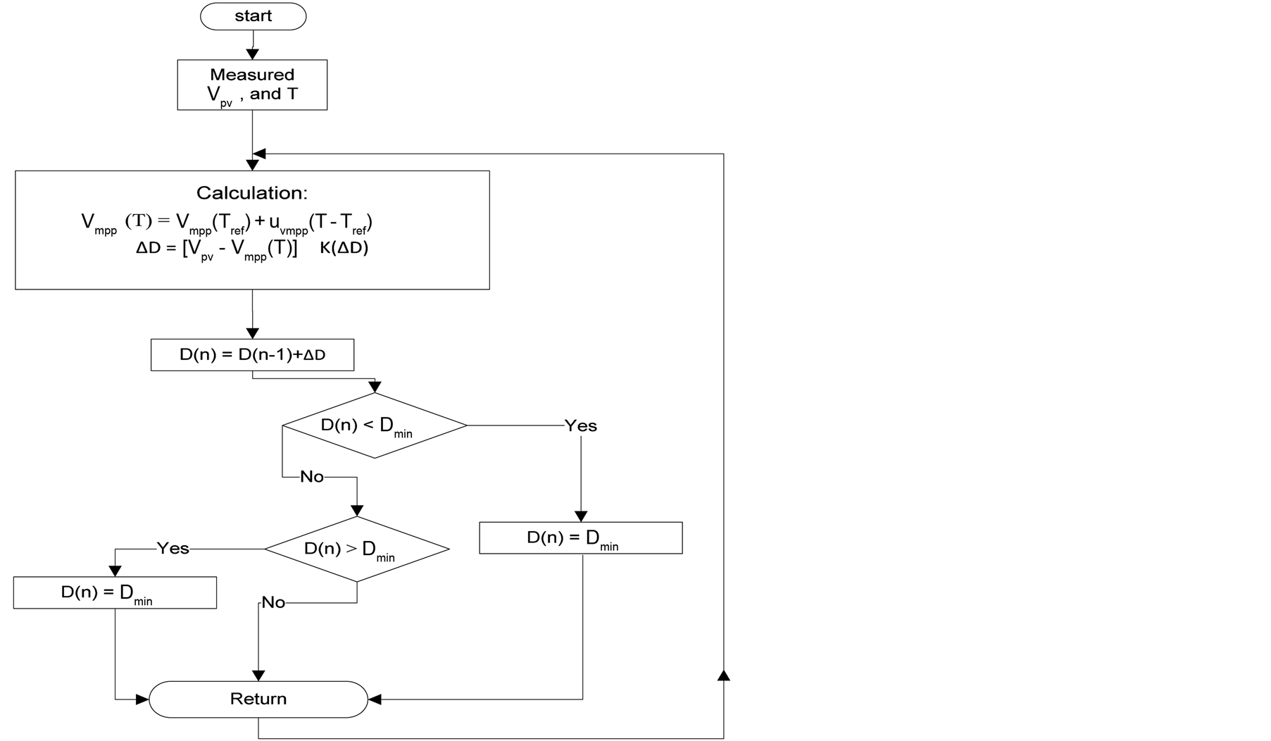
Figure 6. Flowchart of temperature method.
method is less efficient than the P & O and IC algorithms [5] . Furthermore, the temperature algorithm requires datasheet information regarding the PV array, and the algorithm has to be updated to ensure accurate operation of the PV system and compensate for parameter changes caused by system aging [23] .
2.5. Open Voltage (OV) Method
The algorithm is introduced by R. Faranda and S. Leva [5]
, and is based on the observation that the voltage of the MPP is always close to
a fixed percentage of the open circuit voltage. The location of the maximum power
point is adjusted by temperature and insolation level within a 2% tolerance band.
The open-voltage algorithm technique selects 76% of the open circuit voltage
 as the optimum operating voltage
 at which the maximum output power can be obtained. This MPPT controller requires
a static switch to be placed in series with the PV array to enable the open circuit
voltage to be measured on demand. Whilst measuring the open circuit voltage, the
current of the PV panel is zero
at which the maximum output power can be obtained. This MPPT controller requires
a static switch to be placed in series with the PV array to enable the open circuit
voltage to be measured on demand. Whilst measuring the open circuit voltage, the
current of the PV panel is zero , so no power is delivered
by the load and so momentarily the energy produced by the photovoltaic system is
lost
[5] .
, so no power is delivered
by the load and so momentarily the energy produced by the photovoltaic system is
lost
[5] .
2.6. Feedback Voltage (Current) Method
A feedback voltage (or current) method has been applied by J. N. H. D. Maheshappa [24] and H. Chihchiang [25] . It is used to tie the bus voltage at a constant level. It operates, as shown in (Figure 7), by comparing the PV voltage with the constant voltage and adjusting the duty cycle (D) of the converter to operate the PV array at a point close to the MPP. The method is low cost, computationally simple, and only uses one feedback control loop. However, it does not consider the effect of variations in temperature and irradiation [19] .
2.7. Fuzzy Logic Control
Fuzzy logic control in MPP applications has become increasingly popular as microcontroller processing power has improved, and costs have reduced [26] . Fuzzy logic controllers have three stages, fuzzification, rule base table lookup, and defuzzification. During fuzzification, numerical input variables are converted into linguistic variables based on a number of defined membership functions [27] . Typically, the greater the number of membership functions used, the more accurately the controller will operate [28] [29] .
The input to the fuzzy logic controller is an error signal, E, and the change in error; E. The user has the flexibility of choosing how to compute E and E. These signals are then converted to linguistic variables which define how the system is to be controlled by the user. The advantage of fuzzy logic control is that it does not need an accurate mathematical model of the system, and it is capable of handle system non-linearity. The main disadvantage of fuzzy logic control is that the effectiveness depends on user knowledge and competency in choosing the correct error computation and developing a suitable rule base table based on the chosen membership functions [30] . Optimised variants of the fuzzy logic MPPT system have been proposed, including adaptive strategies that tune the membership functions and rule base table in real time [4] .
2.8. Neural Network
A neural network approach is presented by T. Hiyama [31] and L. Zhang [32] . To guarantee accurate MPPT operation, the neural network has to be trained to operate with the PV array and adjust for time varying characteristics of the system. Once trained, the neural network does not require detail information about the PV system;
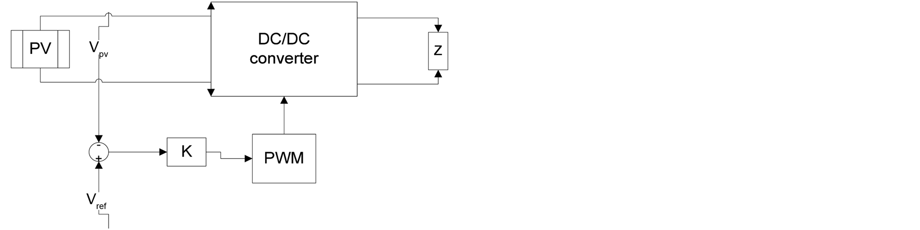
Figure 7. Voltage-feedback with PWM modulation.
it operates like a black box model. In [31] , the neural network has three layers: input layer, hidden layer, and output layer. The number of nodes in each layer varies and is user dependent. The PV array Voc and Isc are used as the input variables. The output is usually represented by one of several reference signals, or the duty cycle signal used to drive power converter. The hidden layers act to achieve the MPP; the performance of the system is heavily dependent on how well a neural network has been initially trained [33] .
3. Discussion
Several MPPT techniques have been discussed in this paper. From this, it is clear that it can be very difficult to choose the best; each MPPT method has its own advantages and disadvantages and the choice is highly application dependent. For example, solar vehicles require fast convergence to the MPP; in this case good options are fuzzy logic control, and neural network. In orbital stations and space satellites, which involve large cost, the performance and reliability of the MPPT are most important. The tracker must be able to continuously track the true MPP in the minimum amount of time and should not require periodic tuning. In this case, the appropriate methods are O & P/Hill-climbing and IC [5] . When using solar panels in residential locations, the objective is to reduce the payback time. To do so, it is necessary to constantly and quickly track the maximum power point. Furthermore, the MPPT should be capable of minimising the ripple around the MPP. Therefore, the two stage IC and optimised P & O methods are suitable.
4. Simulation Results
A diagram of a proposed standalone photovoltaic system is illustrated in (Figure 8). The system is modelled in MATLAB/Simulink. A boost converter is used to interface a PV array to a resistive load. The inductance of the boost converter is 2 mH, input capacitance is 9.4 µF, and output capacitor is 144 µF. To perform the maximum power point tracking, both P & O and IC algorithms have been implemented with all consideration of the optimization techniques. The simulation allows verification of the feasibility and relative performance of both algorithms under correctly the same conditions. Here, the main aspect to consider is the dynamic performance in terms of the speed at which the system converges on maximum power point, and the ripple in the power due to oscillations around the maximum power point at steady state conditions.
The characteristics of the simulated PV panels are shown in Table1 The output power of the solar array is mainly influenced by ambient temperature and irradiation. However, typically, the variations in temperature are slower than the possible changes in irradiation. For this reason, temperature has less impact on the dynamic response of the system. For this reason, the solar array working temperature is fixed at 25˚C in the simulation, and the impact of irradiation is considered in detail. In practice, fast moving, intermittent, clouds can lead to sudden changes in the output power of the solar array. Therefore, the algorithms have to be tested under different irradiation levels to verify the dynamic performance of the tracking the maximum power point tracking.
The simulation results are shown in (Figures 9-14). In the tests, irradiation is abruptly increased from 200 w/m² to 500 w/m² at 1.0 s, and then increased again to 1000 w/m² at 2.0 s. These figures represent the performance and effectiveness of both P & O and IC algorithms using the same fixed step size of 0.03. As the irradiation changes, both algorithms adjust the duty cycle applied to the boost converter to track the new MPP.
In most practical applications, the load connected to the PV system may also be subject to change. Depending on whether the system is lightly, or heavily, loaded may impact on the performance of the MPPT system as it affects the load line of the overall PV system. For this reason (Figures 15-17) present results for varying irradi.
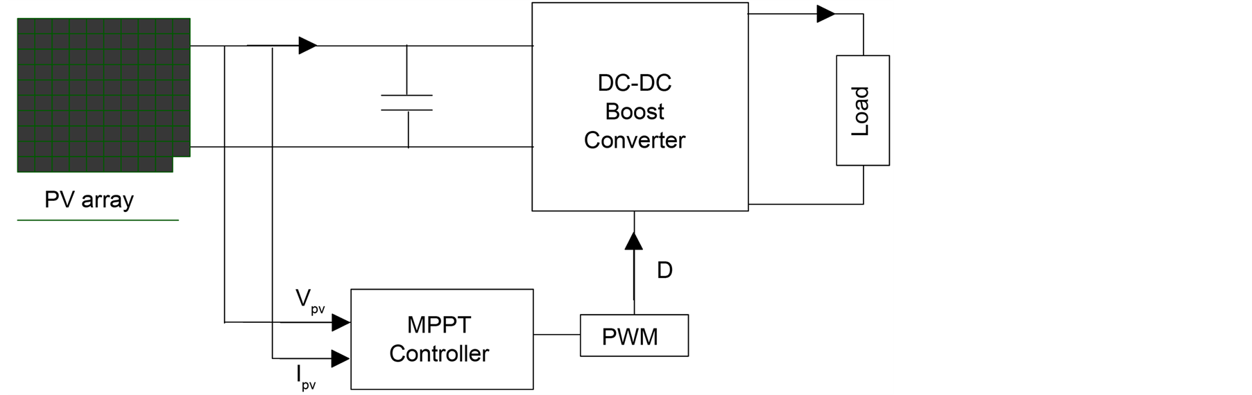
Figure 8. Block diagram of standalone PV system.
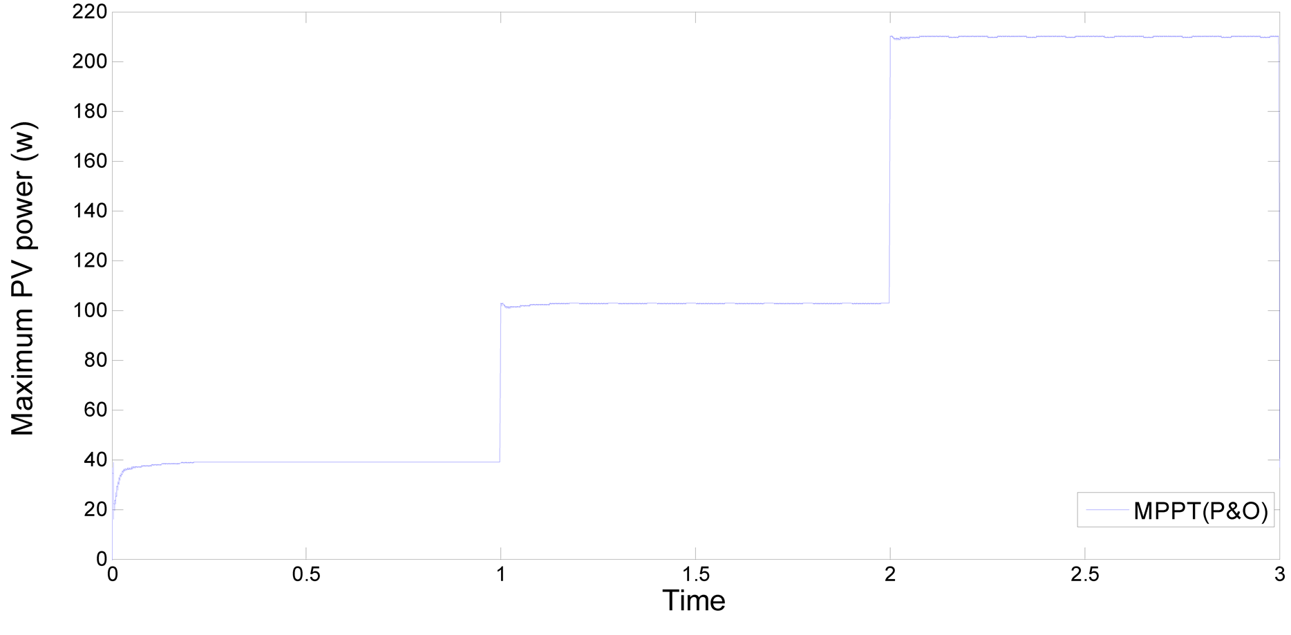
Figure 9. Output power of 210 watt PV module using P & O algorithm.
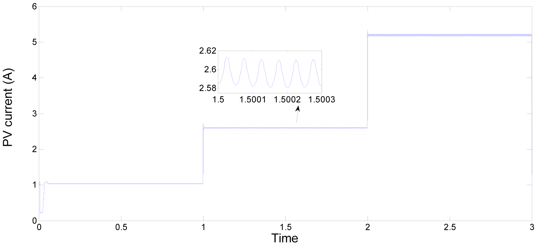
Figure 10. Output current of 210 watt PV module using P & O algorithm.

Figure 11. Duty ratio signal to the switch using P & O algorithm.

Figure 12. Output power of 210 watt PV module using IC algorithm.
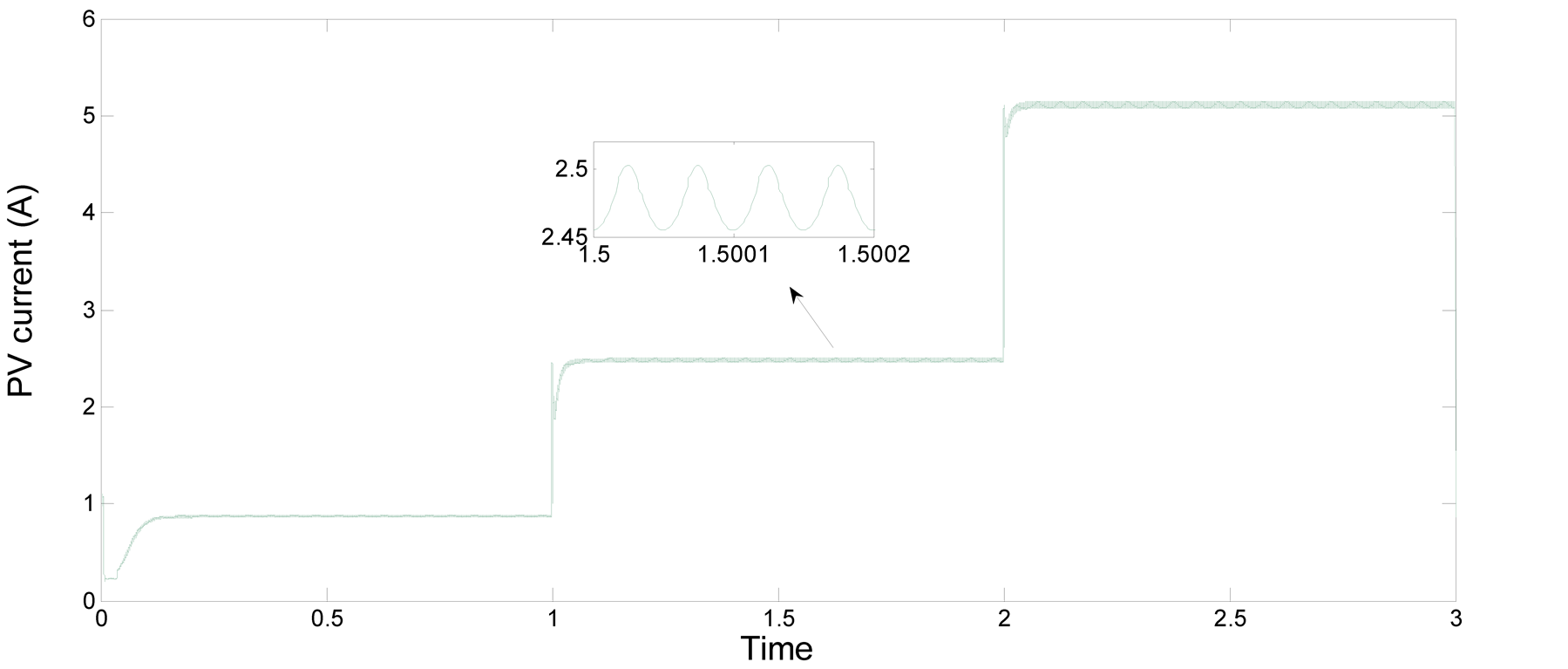
Figure 13. Output current of 210 watt PV module using IC algorithm.

Figure 14. Duty ratio signal to the switch using IC algorithm.
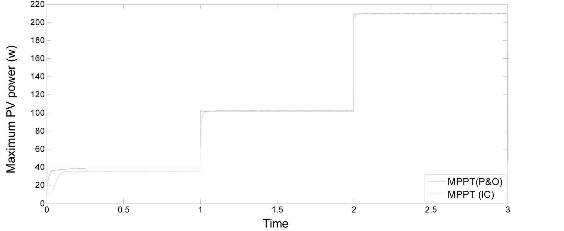
Figure 15. Output power of 210 watt PV module with load 195 Ohm: comparison to P & O with IC under increase in irradiation.
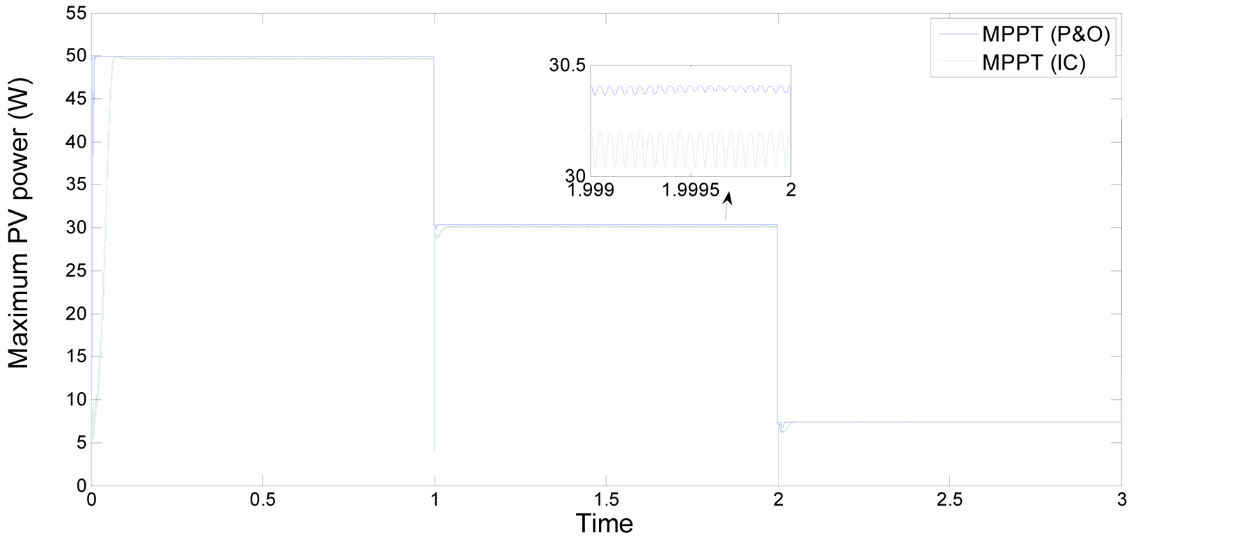
Figure 16. Output power of 50 watt PV module with load 100 Ohm: comparison to P & O with IC under decrease in irradiation.
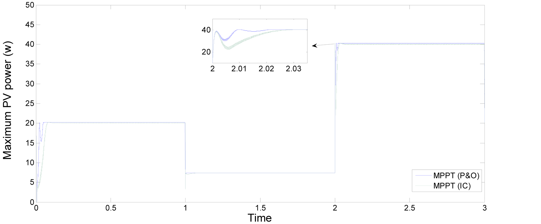
Figure 17. Output power of 50 watt PV module with load 100 Ohm: comparison to P & O with IC under decrease and increase in irradiation.
ance with different load profiles. The results demonstrate that both algorithms exhibit a fast response, but closer inspection reveals the P & O algorithm has a quicker response and less oscillatory behaviour after reaching the steady state.
5. Conclusion
This paper presents an overview of MPPT methods, and considers their suitability in systems which experience a wide range of operating conditions. From this, it is clear that each MPPT method has its own advantages and disadvantages and the choice is highly application-dependent. When using solar panels in residential locations, the objective is to reduce the payback time. To do so, it is necessary to constantly and quickly track the maximum power point. Furthermore, the MPPT should be capable of minimising the ripple around the MPP. Therefore, the two techniques stages—incremental conductance (IC) and perturbation and observation (P & O) algorithms are suitable. These two methods have been evaluated by simulating a standalone PV system, utilising a DC-DC boost converter to connect the PV panel to the load. In particular, the performance of each method has been considered over a wide range of different irradiation conditions. Results show that the enhance of perturb and observe algorithm exhibits faster dynamic performance and achieves steady state level better than the incremental conductance method over a broad range of irradiation settings and load profiles.
References
- Subudhi, B. and Pradhan, R. (2013) A Comparative Study on Maximum Power Point Tracking Techniques for Photovoltaic Power Systems. IEEE Transactions on Sustainable Energy, 4, 89-98.http://dx.doi.org/10.1109/TSTE.2012.2202294
- Gurung, A. (2011) Green Investing 2011. Reducing the Cost of Financing. World Economic Forum USA Inc., USA.
- Martinot, E. and Sawin, J.L. (2012) Renewables 2012 Global Status Report. Renewable Energy Policy Network for the 21st Century.
- Esram, T. and Chapman, P.L. (2007) Comparison of Photovoltaic Array Maximum Power Point Tracking Techniques. IEEE Transactions on Energy Conversion, 22, 439-449. http://dx.doi.org/10.1109/TEC.2006.874230
- Faranda, R. and Leva, S. (2008) Energy Comparison of MPPT Techniques for PV Systems. WSEAS Transactions on Power Systems, 3, 447-455.
- Sera, D., Kerekes, T., Teodorescu, R. and Blaabjerg, F. (2006) Improved MPPT Method for Rapidly Changing Environmental Conditions. 2006 IEEE International Symposium on Industrial Electronics, 2, 1420-1425. http://dx.doi.org/10.1109/ISIE.2006.295680
- Femia, N., Lisi, G., Petrone, G., Spagnuolo, G. and Vitelli, M. (2008) Distributed Maximum Power Point Tracking of Photovoltaic Arrays: Novel Approach and System Analysis. IEEE Transactions on Industrial Electronics, 55, 2610-2621. http://dx.doi.org/10.1109/TIE.2008.924035
- Ali, A.N.A., Saied, M.H., Mostafa, M.Z. and Abdel-Moneim, T.M. (2012) A Survey of Maximum PPT Techniques of PV Systems. 2012 IEEE Energytech, Cleveland, 29-31 May 2012, 1-17.
- Narendiran, S. (2013) Grid Tie Inverter and MPPT—A Review. 2013 International Conference on Circuits, Power and Computing Technologies (ICCPCT), 20-21 March 2013, 564-567. http://dx.doi.org/10.1109/ICCPCT.2013.6529017
- Barakati, M., Kazerani, M. and Aplevich, D. (2009) Maximum Power Tracking Control for a Wind Turbine System Including a Matrix Converter. IEEE Power & Energy Society General Meeting, 24, 705-713.
- Chen, L.R., Tsai, C.H., Lin, Y.L. and Lai, Y.S. (2010) A Biological Swarm Chasing Algorithm for Tracking the PV Maximum Power Point. IEEE Transactions on Energy Conversion, 25, 484-493. http://dx.doi.org/10.1109/TEC.2009.2038067
- Elgendy, M.A., Zahawi, B. and Atkinson, D.J. (2012) Assessment of Perturb and Observe MPPT Algorithm Implementation Techniques for PV Pumping Applications. IEEE Transactions on Sustainable Energy, 3, 21-33.
- Femia, N., Petrone, G., Spagnuolo, G. and Vitelli, M. (2005) Optimization of Perturb and Observe Maximum Power Point Tracking Method. IEEE Transactions on Power Electronics, 20, 963-973. http://dx.doi.org/10.1109/TPEL.2005.850975
- Dorofte, C., Borup, U. and Blaabjerg, F. (2005) A Combined Two-Method MPPT Control Scheme for Grid-Connected Photovoltaic Systems. 2005 European Conference on Power Electronics and Applications, Dresden, 11-14 September 2005, 10. http://dx.doi.org/10.1109/EPE.2005.219714
- Liu, C., Wu, B. and Cheung, R. (2004) Advanced Algorithm for MPPT Control of Photovoltaic Systems. Canadian Solar Buildings Conference, Montreal, 20-24 August 2004.
- Yafaoui, A., Wu, B. and Cheung, R. (2007) Implementation of Maximum Power Point Tracking Algorithm for Residenial Photovoltaic Systems. 2nd Canadian Solar Buildings Conference, Calgary, 10-14 June 2007.
- Subudhi, B. and Pradhan, R. (2012) A Comparative Study on Maximum Power Point Tracking Techniques for Photovoltaic Power Systems. IEEE Transactions on Sustainable Energy, 4, 89-98. http://dx.doi.org/10.1109/TSTE.2012.2202294
- Giustiniani, A., Petrone, G., Spagnuolo, G. and Vitelli, M. (2010) Low-Frequency Current Oscillations and Maximum Power Point Tracking in Grid-Connected Fuel-Cell-Based Systems. IEEE Transactions on Industrial Electronics, 57, 2042-2053. http://dx.doi.org/10.1109/TIE.2009.2034175
- Salas, V., Olias, E., Barrado, A. and Lazaro, A. (2006) Review of the Maximum Power Point Tracking Algorithms for Stand-Alone Photovoltaic Systems. Solar Energy Materials and Solar Cells, 90, 1555-1578. http://dx.doi.org/10.1016/j.solmat.2005.10.023
- Kuo, Y.C., Liang, T.J. and Chen, J.F. (2001) Novel Maximum-Power-Point-Tracking Controller for Photovoltaic Energy Conversion System. IEEE Transactions on Industrial Electronics, 48, 594-601. http://dx.doi.org/10.1109/41.925586
- Lee, J.H., Bae, H. and Cho, B.H. (2006) Advanced Incremental Conductance MPPT Algorithm with a Variable Step Size. 12th International Power Electronics and Motion Control Conference, EPE-PEMC 2006, Portoroz, 30 August-1 September 2006, 603-607.
- Tse, K.K., Chung, H.S.H., Hui, S.Y.R. and Ho, M.T. (2001) A Novel Maximum Power Point Tracking Technique for PV Panels. 2001 IEEE 32nd Annual Power Electronics Specialists Conference, PESC 2001, 4, 1970-1975.
- Coelho, R.F., Concer, F.M. and Martins, D.C. (2010) A MPPT Approach Based on Temperature Measurements Applied in PV Systems. 2010 9th IEEE/IAS International Conference on Industry Applications (INDUSCON), São Paulo, 8-10 November 2010, 1-6.
- Maheshappa, J.N.H.D. and Murthy, M.V. (1998) An Improved Maximum Power Point Tracker Using a Step-Up Converter with Current Locked Loop. Renewable Energy, 13, 195-201. http://dx.doi.org/10.1016/S0960-1481(97)00071-2
- Chihchiang, H. and Chihming, S. (1998) Comparative Study of Peak Power Tracking Techniques for Solar Storage System. 13th Annual Applied Power Electronics Conference and Exposition, APEC’98, Conference Proceedings 1998, 2, 679-685.
- Hilloowala, R.M. and Sharaf, A.M. (1992) A Rule-Based Fuzzy Logic Controller for a PWM Inverter in Photo-Voltaic Energy Conversion Scheme. Conference Record of the 1992 IEEE Industry Applications Society Annual Meeting, 1, 762-769.
- Karbakhsh, M., Abutorabi, H. and Khazaee, A. (2012) An Enhanced MPPT Fuzzy Control of a Wind Turbine Equipped with Permanent Magnet Synchronous Generator. 2012 2nd International Conference on Computer and Knowledge Engineering (ICCKE), Mashhad, 18-19 October 2012, 77-82.
- Mahmoud, A.M.A., Mashaly, H.M., Kandil, S.A., El Khashab, H. and Nashed, M.N.F. (2000) Fuzzy Logic Implementation for Photovoltaic Maximum Power Tracking. 26th Annual Conference of the IEEE Industrial Electronics Society, IECON 2000, 1, 735-740.
- Mahmoud, A.M.A., Mashaly, H.M., Kandil, S.A., El Khashab, H. and Nashed, M.N.F. (2000) Fuzzy Logic Implementation for Photovoltaic Maximum Power Tracking. Proceedings of 9th IEEE International Workshop on Robot and Human Interactive Communication, RO-MAN 2000, Osaka, 27-29 September 2000, 155-160.
- Patcharaprakiti, N. and Premrudeepreechacharn, S. (2002) Maximum Power Point Tracking Using Adaptive Fuzzy Logic Control for Grid-Connected Photovoltaic System. IEEE Power Engineering Society Winter Meeting, 1, 372-377.
- Hiyama, T., Kouzuma, S. and Imakubo, T. (1995) Identification of Optimal Operating Point of PV Modules Using Neural Network for Real Time Maximum Power Tracking Control. IEEE Transactions on Energy Conversion, 10, 360-367. http://dx.doi.org/10.1109/60.391904
- Zhang, L., Bai, Y.F. and Al-Amoudi, A. (2002) GA-RBF Neural Network Based Maximum Power Point Tracking for Grid-Connected Photovoltaic Systems. International Conference on Power Electronics, Machines and Drives, 4-7 June 2002, 18-23.
- Sayal, A. (2012) MPPT Techniques for Photovoltaic System under Uniform Insolation and Partial Shading Conditions. 2012 Students Conference on Engineering and Systems (SCES), Allahabad, 16-18 March 2012, 1-6.