Open Journal of Acoustics
Vol.3 No.3A(2013), Article ID:36870,5 pages DOI:10.4236/oja.2013.33A006
Ultrasonic Spray Coating for Proton Exchange Membrane Fuel Cell
Department of Mechanical Engineering, Fuel cell center, Yuan Ze University, Taoyuan, Taiwan
Email: *s968706@gmail.com
Copyright © 2013 Ting-Chu Jao et al. This is an open access article distributed under the Creative Commons Attribution License, which permits unrestricted use, distribution, and reproduction in any medium, provided the original work is properly cited.
Received July 18, 2013; revised August 18, 2013; accepted August 25, 2013
Keywords: Fuel Cell; Proton Exchange Membrane Fuel Cell (PEMFC); Ultrasonic Spray Coating; Ultrasound
ABSTRACT
Ultrasound is now a widely used method for catalyst synthesis, catalyst support treatment, catalyst layer fabrication, membrane electrode assembly (MEA) fabrication, and humidifier etc. for fuel cell applications. Among the abovementioned uses, ultrasonic technology has been utilised mainly for MEA fabrication—especially since it has demonstrated the capability to produce ultra-low platinum loadings. This paper reports the power density and cathode mass power density at peak power and 500 mA/cm2 conditions for ultrasonically spray coated MEAs. These MEAs were also produced with various Nafion® content ratios and platinum loadings. The results indicate varying optimum values for different conditions.
1. Introduction
Climate change and global warming have made green energy and the reduction of carbon emissions urgent and popular topics. The Proton Exchange Membrane Fuel Cell (PEMFC) is a promising power source of the future because of its high power density, high efficiency, lack of harmful emissions, high quality power, scalability and quick start-up. Figures 1 and 2 are schematic representations of a fuel cell system and a fuel cell unit. The MEA is shown in Figure 2; these are repeating units in a fuel cell and constitute 30% - 50% of the total fuel cell cost. One of the main impeding factors for fuel cell commercialisation is the high cost. For portable device and vehicular applications, fuel cells are competing with batteries and internal combustion engines, respectively. These competitors have been operating commercially for almost a century with well-established infrastructure. Since the MEA is the most expensive component of fuel cells, reducing platinum loading of MEAs is an important research area for fuel cell development.
Ultrasound is widely used for many applications. For fuel cell fabrication, it is very commonly used to prepare catalyst inks. Besides ink fabrication, literature has also shown ultrasound being used to assist catalyst synthesis [1,2], catalyst support treatment [3], MEA fabrication [4-6] and humidifier [7] among others. Among these applications, ultrasonically spray coated MEAs have shown remarkable platinum mass power density [4,6]. In general, MEAs can be prepared using three different methods: 1) Catalyst coated membrane (CCM), where the catalyst layer (CL) is transferred directly onto a membrane; 2) Decal transfer CCM, where the CL is coated on a substrate and then transferred onto a membrane, or 3) Catalyst coated substrate (CCS), which entails coating the CL on the gas diffusion layers (GDL) [4].
An MEA is fabricated by sandwiching a CCM between two GDLs, or sandwiching a PEM between two gas diffusion electrodes (GDEs are GDL with CL). The ultrasonic spray coating technique can be used for CCM and CCS methods. Normally, MEAs fabricated by CCM demonstrate better performance than CCS. The CCM delivers lower resistance than CCS due to improved CL-membrane ionic contact.
Aiming at lower cost MEAs, literature shows many coating methods for fabricating ultra-low platinum loading MEAs such as sputter deposition [8-10], ion-bean assisted deposition [11-14], doctor blade [15], screen printing [16], inkjet printing [17-19], spraying [20], electrospraying [21-28] and ultrasonic spraying [4,6]. Most of the methods mentioned showed remarkable platinum mass power density and good performance, but under unrealistic and unpractical operating conditions (pure

Figure 1. The schematic of fuel cell system.
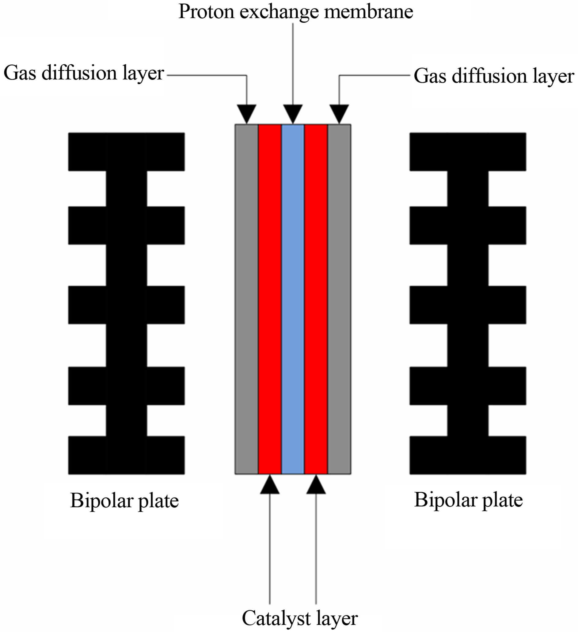
Figure 2. The schematic of fuel cell unit.
oxygen oxidants or high back pressure), with the exception of the ultrasonic spraying method [4].
2. Experimental
Catalyst inks consisted of supported catalyst (40 wt% Pt/C, Johnson Matthey HiSpecTM 4000), aqueous Nafion® solution (5 wt%), DI water, and ethanol. All the contents were added to a glass vial and mixed using an ultrasonic bath. The ratio of the supported catalyst to Nafion® was 2:1. The catalyst inks were loaded into SonoTek ‘Exacta-coat’ then sprayed onto the Nafion® 212 membrane directly. The anode platinum loading was fixed at 0.116 mg/cm2 while various platinum loadings were tested for the cathode. The ultrasonic spray coating machine as shown as Figure 3. The active area of MEAs was about 5 cm2. Each CCM was sandwiched between two GDLs and assembled in a single cell without hot press for fuel cell performance tests. The channel depth, channel width, and rib width of the serpentine flow field plate were all 1 mm. All fuel cell performance measurements were performance with a Fuel Cell Test System 850C (Scribner Associates Incorporated, USA). The operating conditions were 65˚C, relative humidity (RH) at 100%, 100 sccm hydrogen flow rate, and 250 sccm air flow rate. No back pressure was used during experiments. The details with regards to the MEA fabrication and single cell testing can be found in a previous study [4].
3. Results and Discussion
Figure 4 shows the relationship between power density, platinum loading and Nafion® content ratio at the peak power condition. It can be seen that an optimum value exists for platinum loading and the Nafion® content ratio. The higher platinum loading can provide more active sites that lead to higher kinetic rates but it increases the CL thickness correspondingly. Thick CLs results in poorer mass transfer. The reaction requires three phase boundaries: solid, liquid and gas phase. The solid phase is Pt/C, and it provides the reaction site and electron transfer route. Nafion®/water is the liquid phase and provides the proton transfer route. The gas phase is the reaction gases (hydrogen/air) which is supplied by the pores.
A similar case can be seen for the Nafion® content ratio. Increasing the Nafion® content ratio can provide
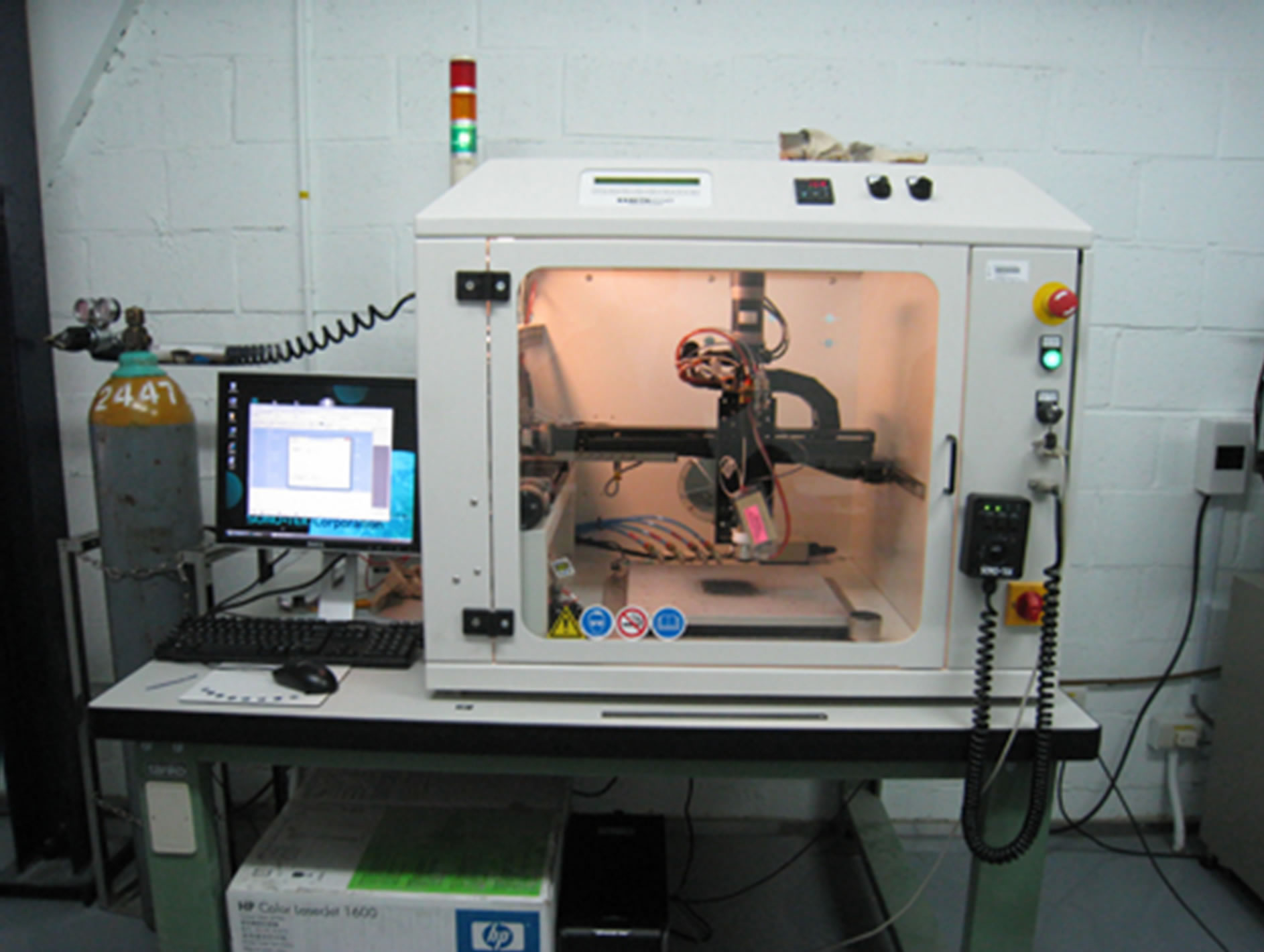
Figure 3. The photo of Sonotek ultrasonic spray coating machine.
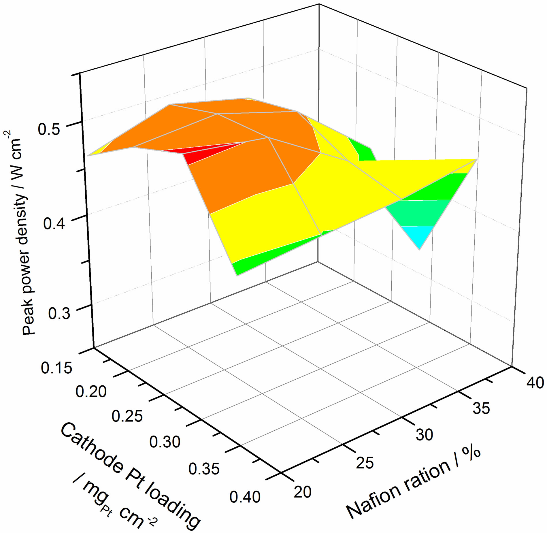
Figure 4. The relation of power density with platinum loading and Nafion contain ratio at peak power condition.
more routes for proton transfer. However, it also increases the CL thickness, leading to greater resistance to mass transfer. Simultaneously, higher Nafion® content ratios can reduce the electron conductivity due to it being a poor electrical conductor besides coating (and thereby insulating) the carbon surface. As a result, there is an optimum value for both platinum loading and Nafion® content ratio.
Figure 5 shows the cathode peak power density against platinum loading and Nafion® content ratio. Here it is noted that lower platinum loadings results in higher mass power densities. Also, with regards to platinum loading, the best performance was only ca. 20% higher than the lowest, even though the loading was more than doubled. The result indicates that the performance does

Figure 5. The relation of cathode mass power density with platinum loading and Nafion contain ratio at peak power condition.
not correspond linearly to platinum loading. The mass power density is the power density normalised to the mass of platinum. Thus, the highest mass power density occurs at the lowest platinum loading. For a fuel cell system cost analysis, the lower platinum loading reduces catalyst cost. However, to achieve similar performance, larger active areas in more cells are required hence resulting in higher costs associated with membranes, GDLs and bipolar plates. As such, the lowest platinum loading does not necessarily correspond to the lowest cost for a fuel cell system.
Figure 6 shows the relationship between power density, platinum loading and Nafion® content ratio at 500 mA/cm2. The optimum value here is obviously different when compared to that at peak power. As the operating current is lowered, the kinetically controlled domain is approached. The 500 mA/cm2 condition is considered to be at the medium current region that is dominated by both kinetics and ohmics. Thus the optimum value is different from the peak power condition because mass transfer did not significantly affect the performance. Figure 7 shows the cathode mass power density against platinum loading and Nafion® content ratio at 500 mA/cm2. The result is very similar to Figure 5. The lowest platinum loading corresponds to the highest mass power density. Therefore, it can be concluded that to minimise the cost of a fuel cell system, the optimum platinum loading is dependent on the performance requirement, and will in turn affect the cost of the other components i.e. lower platinum loading, more cells required.
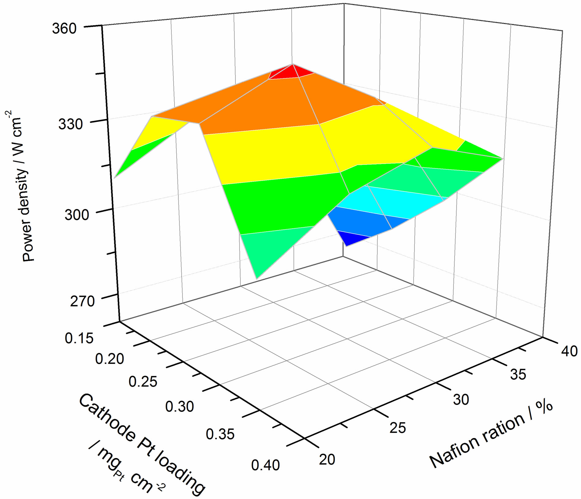
Figure 6. The relation of power density with platinum loading and Nafion contain ratio at 500 mA·cm−2 condition.

Figure 7. The relation of cathode mass power density with platinum loading and Nafion contain ratio at 500 mA·cm−2 condition.
4. Conclusions
Ultrasonic spray coating technology has only been used for fuel cell applications in recent years. It has been demonstrated that ultrasonic spray coating is an effective way to reduce platinum loading for fuel cells. The optimum catalyst ink formula and platinum loading are dependent on operating conditions. In terms of cost, optimum platinum loadings must be considered alongside the cost of other core components. This extended cost analysis is a helpful approach to lower the cost of fuel cell systems. Normally, direct methanol fuel cells and high temperature PEMFCs require more catalyst than low temperature PEMFCs. As such, ultrasonic spray coating technology has great potential for the fabrication of direct methanol fuel cells and high temperature PEMFCs.
5. Acknowledgements
The authors gratefully acknowledge the National Science Council of Taiwan under contracts 101-2622-E-155-004- CC2, 100-2221-E-155-082-MY2, 102-2221-E-155-005- MY3, and 102-2622-E-155-001-CC2.
REFERENCES
- J.-H. Jang, C. Pak and Y.-U. Kwon, “Ultrasound-Assisted Polyol Synthesis and Electrocatalytic Characterization of PdxCo Alloy and Core-Shell Nanoparticles,” Journal of Power Source, Vol. 201, 2012, pp. 179-183. doi:10.1016/j.jpowsour.2011.10.139
- I. Choi, K. G. Lee, S. H. Ahn, D. H. Kim, O. J. Kwon and J. J. Kim, “Sonochemical Synthesis of Pt-Deposited SiO2 Nanocomposite and Its Catalytic Application for Polymer Electrolyte Membrane Fuel Cell Under Low-Humidity Conditions,” Catalysis Communications, Vol. 21, 2012, pp. 86-90. doi:10.1016/j.catcom.2012.02.005
- C. Yang, X. Hu, D. Wang, C. Dai, L. Zhang, H. Jin, et al., “Ultrasonically Treated Multi-Walled Carbon Nanotubes (MWCNTs) as PtRu Catalyst supports for Methanol Electrooxidation,” Journal of Power Sources, Vol. 160, No. 1, 2006, pp. 187-193. doi:10.1016/j.jpowsour.2006.05.015
- T.-H. Huang, H.-L. Shen, T.-C. Jao, F.-B. Weng and A. Su, “Ultra-Low Pt Loading for Proton Exchange Membrane Fuel Cells by Catalyst Coating Technique with Ultrasonic Spray Coating Machine,” International Journal of Hydrogen Energy, Vol. 37, No. 18, 2012, pp. 13872- 13879. doi:10.1016/j.ijhydene.2012.04.108
- Y. Devrim, S. Erkan, N. Baç and I. Eroglu, “Improvement of PEMFC Performance with Nafion/Inorganic Nanocomposite Membrane Electrode Assembly Prepared by Ultrasonic Coating Technique,” International Journal of Hydrogen Energy, Vol. 37, No. 21, 2012, pp. 16748- 16758. doi:10.1016/j.ijhydene.2012.02.148
- B. Millington, V. Whipple and B. G. Pollet, “A Novel Method for Preparing Proton Exchange Membrane Fuel Cell Electrodes by the Ultrasonic-Spray Technique,” Journal of Power Sources, Vol. 196, No. 20, 2011, pp. 8500-8508. doi:10.1016/j.jpowsour.2011.06.024
- C.-C. Sung, C.-Y. Bai, J.-H. Chen and S.-J. Chang, “Controllable Fuel Cell Humidification by Ultrasonic Atomization,” Journal of Power Sources, Vol. 239, 2013, pp. 151- 156. doi:10.1016/j.jpowsour.2013.03.076
- M. Cavarroc, A. Ennadjaoui, M. Mougenot, P. Brault, R. Escalier, Y. Tessier, et al., “Performance of Plasma Sputtered Fuel Cell Electrodes with Ultra-Low Pt Loadings,” Electrochemistry Communications, Vol. 11, No. 4, 2009, pp. 859-861. doi:10.1016/j.elecom.2009.02.012
- M. D. Gasda, G. A. Eisman and D. Gall, “Sputter-Deposited Pt/CrN Nanoparticle PEM Fuel Cell Cathodes: Limited Proton Conductivity Through Electrode Dewetting,” Journal of The Electrochemical Society, Vol. 157, No. 1, 2010, pp. B71. doi:10.1149/1.3247351
- M. Mougenot, A. Caillard, P. Brault, S. Baranton and C. Coutanceau, “High Performance Plasma Sputtered PdPt Fuel Cell Electrodes with Ultra Low Loading,” International Journal of Hydrogen Energy, Vol. 36, No. 14, 2011, pp. 8429-8434. doi:10.1016/j.ijhydene.2011.04.080
- M. Saha, A. Gulla, R. Allen and S. Mukerjee, “High Performance Polymer Electrolyte Fuel Cells with Ultra-Low Pt Loading Electrodes Prepared by Dual Ion-Beam Assisted Deposition,” Electrochimica Acta, Vol. 51, No. 22, 2006, pp. 4680-4692. doi:10.1016/j.electacta.2006.01.006
- A. F. Gullá, M. S. Saha, R. J. Allen, S. Mukerjee, “Dual Ion-Beam-Assisted Deposition as a Method to Obtain Low Loading-High Performance Electrodes for PEMFCs,” Electrochemical and Solid-State Letters, Vol. 8, No. 10, 2005, p. A504.
- A. F. Gullá, M. S. Saha, R. J. Allen and S. Mukerjee, “Toward Improving the Performance of PEM Fuel Cell by Using Mix Metal Electrodes Prepared by Dual IBAD,” Journal of The Electrochemical Society, Vol. 153, No. 2, 2006, p. A366.
- N. Ramaswamy, T. M. Arruda, W. Wen, N. Hakim, M. Saha, A. Gullá, et al., “Enhanced Activity and Interfacial Durability Study of Ultra Low Pt Based Electrocatalysts Prepared by Ion Beam Assisted Deposition (IBAD) Method,” Electrochimica Acta, Vol. 54, No. 26, 2009, pp. 6756-6766. doi:10.1016/j.electacta.2009.06.040
- I.-S. Park, W. Li and A. Manthiram, “Fabrication of Catalyst-Coated Membrane-Electrode Assemblies by Doctor Blade Method and Their Performance in Fuel Cells,” Journal of Power Sources, Vol. 195, No. 20, 2010, pp. 7078-7082. doi:10.1016/j.jpowsour.2010.05.004
- R. N. Bonifácio, J. O. A. Paschoal, M. Linardi, R. Cuenca, “Catalyst Layer Optimization by Surface Tension Control During Ink Formulation of Membrane Electrode Assemblies in Proton Exchange Membrane Fuel Cell,” Journal of Power Sources, Vol. 196, No. 10, 2011, pp. 4680-4685. doi:10.1016/j.jpowsour.2011.01.010
- A. D. Taylor, E. Y. Kim, V. P. Humes, J. Kizuka and L. T. Thompson, “Inkjet Printing of Carbon Supported Platinum 3-D Catalyst Layers for Use in Fuel Cells,” Journal of Power Sources, Vol. 171, No. 1, 2007, pp. 101-106. doi:10.1016/j.jpowsour.2007.01.024
- M. S. Saha, D. K. Paul, D. Malevich, B. A. Peppley and K. Karan, “Preparation of Ultra-Thin Catalyst Layers by Piezo-Electric Printer for PEMFCs Applications,” Vienna, 2009. pp. 2049-2059.
- M. S. Saha, D. Malevich, E. Halliop, J. G. Pharoah, B. A. Peppley and K. Karan, “Electrochemical Activity and Catalyst Utilization of Low Pt and Thickness Controlled Membrane Electrode Assemblies,” Journal of The Electrochemical Society, Vol. 158, No. 5, 2011, p. B562. doi:10.1149/1.3559188
- C. Hsu, “An Innovative Process for PEMFC Electrodes Using the Expansion of Nafion Film,” Journal of Power Sources, Vol. 115, No. 2, 2003, pp. 268-273. doi:10.1016/S0378-7753(03)00005-3
- S. Martin, P. L. Garcia-Ybarra and J. L. Castillo, “Electrospray Deposition of Catalyst Layers with Ultra-Low Pt Loadings for PEM Fuel Cells Cathodes,” Journal of Power Sources, Vol. 195, No. 9, 2010, pp. 2443-2449. doi:10.1016/j.jpowsour.2009.11.092
- R. Benítez, A. M. Chaparro and L. Daza, “Electrochemical Characterisation of Pt/C Suspensions for the Reduction of Oxygen,” Journal of Power Sources, Vol. 151, 2005, pp. 2-10. doi:10.1016/j.jpowsour.2005.02.077
- R. Benítez, J. Soler and L. Daza, “Novel method for Preparation of PEMFC Electrodes by the Electrospray Technique,” Journal of Power Sources, Vol. 151, 2005, pp. 108-113. doi:10.1016/j.jpowsour.2005.02.047
- A. M. Chaparro, R. Benítez, L. Gubler, G. G. Scherer and L. Daza, “Study of Membrane Electrode Assemblies for PEMFC, with Cathodes Prepared by the Electrospray Method,” Journal of Power Sources, Vol. 169, No. 1, 2007, pp. 77-84. doi:10.1016/j.jpowsour.2007.01.044
- A. M. Chaparro, B. Gallardo, M. A. Folgado, A. J. Martín and L. Daza, “PEMFC Electrode Preparation by Electrospray: Optimization of Catalyst Load and Ionomer Content,” Catalysis Today, Vol. 143, No. 3-4, 2009, pp. 237-241.
- A. M. Chaparro, M. A. Folgado, P. Ferreira-Aparicio, A. J. Martín, I. Alonso-Álvarez and L. Daza, “Properties of Catalyst Layers for PEMFC Electrodes Prepared by Electrospray Deposition,” Journal of The Electrochemical Society, Vol. 157, No. 7, 2010, pp. B993.
- S. Martin, P. L. Garcia-Ybarra and J. L. Castillo, “High Platinum Utilization in Ultra-Low Pt Loaded PEM Fuel Cell Cathodes Prepared by Electrospraying,” International Journal of Hydrogen Energy, Vol. 35, No. 19, 2010, pp. 10446-10451. doi:10.1016/j.ijhydene.2010.07.069
- A. M. Chaparro, P. Ferreira-Aparicio, M. A. Folgado, A. J. Martín and L. Daza, “Catalyst Layers for Proton Exchange Membrane Fuel Cells Prepared by Electrospray Deposition on Nafion Membrane,” Journal of Power Sources, Vol. 196, No. 9, 2011, pp. 4200-4208. doi:10.1016/j.jpowsour.2010.09.096
NOTES
*Corresponding author.