World Journal of Engineering and Technology
Vol.04 No.01(2016), Article ID:63369,8 pages
10.4236/wjet.2016.41006
Numerical Analysis of Thermo-Elastic Contact Problem of Disc Brakes for Vehicle on Gradient Surfaces
Moses Omolayo Petinrin1*, Adewale Adedayo Oyedele2, Olusegun Olufemi Ajide1
1Department of Mechanical Engineering, University of Ibadan, Ibadan, Nigeria
2Prototype Engineering Development Institute, National Agency for Science and Engineering Infrastructure, Ilesa, Nigeria

Copyright © 2016 by authors and Scientific Research Publishing Inc.
This work is licensed under the Creative Commons Attribution International License (CC BY).
http://creativecommons.org/licenses/by/4.0/


Received 26 October 2015; accepted 1 February 2016; published 5 February 2016
ABSTRACT
In this study, the thermo-elastic effects of frictional heat generation in a disc brake system due to braking actions were simulated. The mathematical model that defined the problem was developed from the kinetic and potential energies of moving vehicles on the gradient surfaces. This problem was solved for the selected geometry of disc brake and pad with their material properties selected from existing literatures using the finite element method and the computational results were obtained. The thermal deformation obtained was in good agreement with similar literature results. Also, for the same braking period and conditions, the results showed that a vehicle ascending a hill gave a higher temperature rise, Von Mises stress and thermal deformation on brake contact surfaces than when descending hill. Therefore, the braking period required to bring a moving vehicle in ascendent motion to a lower speed is expected to be shorter because of the gravity effect than horizontal motion, while descendent motion requires longer braking period.
Keywords:
Braking Action, Frictional Heat, Gradient, Thermal Load, Thermo-Elastic

1. Introduction
The most important safety component of a vehicle is the braking system as it is used to control the speed of a vehicle through the contact action of brake drum or brake disc and brake pads [1] . Disc brakes require pad friction material to have a greater resistance to high temperature because they operate at much higher temperature than drum brakes [2] [3] . Essential factor in consistent brake performance is maintaining the operating temperatures within the effective range of the pad material being used by controlling the flow of cooling air from the brake ducts [4] .
Extended and repetitive braking actions on a car in mountain descent always lead to heat generation which can result in brake fluid temperature rise and subsequent brake fluid vaporization [5] . The resulting rise in temperatures has pronounced and deleterious effects on the performance of the braking system [6] .
This may be a concern particularly for passenger cars equipped with aluminium calipers and with a limited air flow to the wheel brake systems. Braking performance of a vehicle can be significantly affected by the temperature rise in the brake components. High temperature during braking may cause brake fade, incipient and premature wear, brake fluid vaporization, bearing failure, thermal cracks, and thermally excited vibration [1] [7] .
Consequently controlling the temperature profiles and thermo-mechanical stresses are critical to proper functioning of the braking system [8] .
Park et al. [9] used the finite element based commercial program SAMCEF to simulate the friction energy that is generated by the sliding contact between a disc and pad during braking, sensitivity analysis was carried out in order to find the sensitive parameters of brake judder which were predicted after the phenomenon was confirmed.
Mostefa and Ali [10] analyzed the thermomechanical behaviour of the dry contact between the brake disc and pads during the braking phase by modelling of transient temperature in the disc and subsequently determined its geometric design factor in order to put the ventilation system in vehicles. They found out that the deformation, Von Mises stress in the disc and the contact pressure distribution in pads were satisfactory when compared to those of the literature.
Wang and Tang [11] discussed the necessity of application of numerical simulation method in research on friction materials of automotive brake, and analyzed and simulated respectively under emergency braking, the dynamic temperature field and thermal stress field of the one brake disc with two kinds of friction plates of different composite materials on resin and the powder metallurgy based on copper. Based on the results obtained they concluded that numerical simulation methods which were proposed can provide effective references for preparation and optimization design of friction materials of braking.
Eltoukhy et al. [12] modelled transient analysis of the thermoelastic contact problem for disc brakes of different types using the finite element analysis (FEA) method. This was done by investigating the influence of material properties of the discs on their thermo-elastic behaviour. It was found out that their proposed numerical model showed a much closed fit with experimental results found in the literature.
Petinrin and Oji [13] compared two brake pad materials (asbestos and aramid) by modelling the heat generation and dissipation in a disc brake during and after braking action. It was established after from their findings that aramid as brake pad material was a good substitute for asbestos which was reportedly releasing toxic dust to environment.
However, in this present work, the mathematical model for fully coupled thermo-elastic instability problem of a disc brake system is developed from the kinetic and potential energies of moving vehicles and analyzed with gray cast iron brake disc and aramid brake pads for a car under braking actions on gradient surfaces: horizontal, descendent and ascendant as potential energy contribution has not been given attention to in the previous studies.
It is pertinent to state here that the wear action due to frictional heat generation between the disc and the pads is assumed to be infinitesimal and disregarded in this analysis.
2. Theoretical Background
Frictional heat generated on the surfaces of the brake disc and brake pads during braking action is as a result of the thermal energy converted from the kinetic and potential energies of a moving vehicle, neglecting drag and other losses outside the brakes, and no skidding of the car tyres on the road surface [14] . Change in car speed and ascending or descending a hill develop these kinetic energy and potential energy respectively.
The kinetic energy of a vehicle of mass, m with an initial velocity, v1 and final velocity v2 can be given as
 (1)
(1)
While its potential energy when ascending or descending a hill can be expressed as
 (2)
(2)
The difference in elevation can be replaced with the slope, s of the hill and horizontal distance between the first point of braking and the point where the brake is released. Therefore, Equation (2) gives
 (3)
(3)
The brakes’ retardation power, P when a vehicle ascends and descends a hill, is given by the time derivative of the total energy absorbed by the braking system
 (4)
(4)
 (5)
(5)
while the angular velocity is given as
 (6)
(6)
the wheel radius is denoted as R and the angular acceleration is α.
At the interface between each of a car four-brake discs and the brake pad the work done per unit time by friction can be determined by the product of the friction force and the disc’s velocity. This work equals the brake’s retardation power when integrated over the surface area of the eight pads (two pads per brake disc) and is given as
 (7)
(7)
Also, determining the frictional force per unit area, Ff of the pad surface from Equations (5) and (7), we have
 (8)
(8)
the pad’s contact area is denoted by A and the distance between the centre of the disc and the pad’s centre of mass is rm.
In solving the transient thermal analysis, the required governing heat equation [15] is given as
 (9)
(9)
Since the total energy generated by the car during the braking action is transformed into heat energy at the wheels, therefore, the heat generated per unit contact area, q0 at time, t and the distance, r from the disc centre for one disc pad’s surface becomes
 (10)
(10)
In order to avoid excessive temperature rise of the brake lining, the friction energy transformed into heat must be dissipated through the non-contact area to the surrounding air [13] .
Giving account for heat dissipated, qd to the surrounding air through convection and radiation from the disc surface, we have
 (11)
(11)
The coefficient of heat transfer h can be determined as a function of the car’s speed, v [16] .
 (12)
(12)
From Equations (11) and (12), T is the temperature, T0 is the ambient temperature, ε is the material’s emissivity, and σ is the Stefan-Boltzmann constant. Also, d is the disc diameter and k represents the thermal conductivity.
For deformation caused by the thermal stress, the invariant form of the dynamic equilibrium equation [13] [17] , can be expressed as
 (13)
(13)
Taking the material of the disc and pads as elastic, homogeneous and isotropic, the constitutive equation for such material is given as constitutive equation for homogeneous, isotropic, and elastic material is given as
 (14)
(14)
and the self-strain due to thermal expansion in the material is
 (15)
(15)
3. The Model and Braking Conditions
This work models the brake disc as a three-dimensional solid with shape and dimensions as in Figure 1. The disc, made of gray cast iron, has a diameter of 0.272 m and the thickness of the disc on the contact surfaces and pad of aramid material is 0.0125 m and 0.0065 m, respectively. The properties of the brake materials with the thermo physical properties of air are listed in Table 1 [15] [18] .
In this analysis, it is assumed that a driver applied the brake of a car of mass 1600 kg, initially travelling at 30 m/s (108 km/h) for 3 s, causing the vehicle to decelerate at the rate of 8 m/s2 and subsequent release of the braking action after this period (Figure 2). This case study was adopted from [13] .
The developed finite element analysis model (Figure 3) contains 10,813 three-dimensional tetrahedral elements and 74,944 degrees of freedom, while the time step used during the numerical computation was 0.01 s. The meshing at the contact zones is refined because temperature varies significantly here and makes the thermomechanical gradients to be very high. The initial temperature used during the simulation was set as 303 K (30 ˚C).
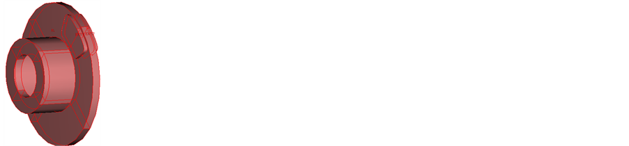
Figure 1. The brake disc CAD model.

Table 1. The brake materials properties and thermophysical properties of air.

Figure 2. The car’s velocity-time graph.

Figure 3. Finite element model of the brake disc.
4. Results and Discussion
For a vehicle experiencing braking action on difference gradient surfaces with the same disc and pads geometrical parameters under the same braking and boundary conditions, the temperature distributions in the brake disc module at time steps of 0.2 s and 2.8 s are as shown in Figure 4. It can be shown that the localized temperature hot spots were generated on the contact surfaces due to the rubbing action. The temperature distributions for each time step look similar but the maximum point temperatures on the brake disc module are as depicted in Table 2.
The comparison between the temperature distributions produced (due to frictional heat generation on contact surface of one of the pad and the brake disc) during and after the braking processes under the same operating conditions for a car experiencing each case of horizontal, descendent and ascendent motion is shown in Figure 5. It indicates that the thermal energy absorbed by the brake system while ascending a hill is more compare to other cases. The decrease in temperature observed after the braking action, that is 3 s, is as a result of the heat dissipation to the surroundings through conduction, convection and radiation.
As a result of the frictional heating between the contact surface stress is induced through thermal load in the contact materials. Figure 6 shows Von Mises stress distributions produced during and after the braking processes on the rubbing surface of one of the two pads. The stress distribution is only influenced by the temperature change as it is shown in the figure because the contact materials are isotropic, which means that the modulus of elasticity, Poisson ratio and the thermal expansion coefficient are assumed constant.
Taking a point in the disc (Figure 7), the displacement curves (Figure 8) obtained also shows that the disc body experiences more deformation while the car is in ascendent motion than other two cases, and the deformations for each case keeps reducing at the end of the braking action.
5. Conclusion
In this work, the analysis of the thermomechanical behaviour of the dry contact between the brake disc and pads was presented; the finite element model was solved using COMSOL Multiphysics. The results obtained showed that temperature distributions and the subsequent stress distributions were proportional as contact materials were
 (a)
(a) (b)
(b) (c)
(c)
Figure 4. The temperature distributions at time steps 0.2 s and 2.8 s respectively for (a) horizontal motion, (b) ascendent motion, and (c) descendent motion.

Figure 5. The temperature distribution on contact surface.
Table 2. Maximum temperatures on brake disc module.

Figure 6. Stress distribution on contact surface.

Figure 7. A point on brake disc.

Figure 8. Displacement curves at a point on brake disc.
considered isotropic. The higher temperature rise and the greater stress accompanied by the rise in temperature while in ascendent motion under the same uniform deceleration with the other two cases are a result of gravity effect which adds to the retardation power or contact pressure. Therefore, the braking period required to bring a moving vehicle in ascendent motion to a lower speed is expected to be shorter because of the gravity effect than horizontal motion, while descendent motion requires longer braking period. This implies that a vehicle subjected to these cases under the same braking period will actually have a lower final speed for ascendent motion than other cases except for the same uniform deceleration.
Cite this paper
Moses OmolayoPetinrin,Adewale AdedayoOyedele,Olusegun OlufemiAjide, (2016) Numerical Analysis of Thermo-Elastic Contact Problem of Disc Brakes for Vehicle on Gradient Surfaces. World Journal of Engineering and Technology,04,51-58. doi: 10.4236/wjet.2016.41006
References
- 1. Belhocine, A., Abu Bakar, A.R. and Bouchetara, M. (2014) Numerical Modeling of Disc Brake System in Frictional Contact. Tribology in Industry, 36, 49-66.
- 2. CDX (2006) Handout Activity: HA525. DVP Licensing Pty Ltd., Brisbane.
- 3. Limberg, J. Introduction to Foundation Brake Design. E and J Enterprises, L.L.C., Bosch, St. Mary’s College, Notre Dame, Indiana. www.sae.org/events/bce/tutorial-limberg.pdf
- 4. AP Racing (2011) Brake Temperatures.
http://www.apracing.com/Info.aspx?InfoID=44&ProductID=2999 - 5. Lee, K. (1999) Numerical Prediction of Brake Fluid Temperature Rise during Braking and Heat Soaking. SAE Technical Paper 1999-01-0483.
http://dx.doi.org/10.4271/1999-01-0483 - 6. Jiguang, C. and Fei, G. (2015) Temperature Field and Thermal Stress Analyses of High-Speed Train Brake Disc Under Pad Variations. The Open Mechanical Engineering Journal, 9, 371-378.
http://dx.doi.org/10.2174/1874155X01509010371 - 7. Siddiqui, S.S. and Dehankar, R.N. (2015) Thermoelastic Analysis of Disc Brake by using ANSYS Software. International Journal on Recent and Innovation Trends in Computing and Communication, 3, 149-152.
- 8. Chavan, P. and Apte, A. (2008) Axisymmetric Analysis of Bolted Disc Brake Assembly to Evaluate Thermal Stresses to Evaluate Thermal Stresses. Abaqus Users’ Meet 1-7.
- 9. Park Park, J.H., Park, T.W., Lee, J.H. and Cho, M.H. (2014) Hot Judder Simulation of a Ventilated Disc and Design of an Improved Disc Using Sensitivity Analysis. International Journal of Automotive Technology, 15, 1-6.
http://dx.doi.org/10.1007/s12239-014-0001-2 - 10. Mostefa, B. and Ali, B. (2014) Thermoelastic Analysis of Disk Brakes Rotor. American Journal of Mechanical Engineering, 2, 103-113.
http://dx.doi.org/10.12691/ajme-2-4-2 - 11. Wang, K. and Tang, J. (2015) Analysis of Thermal-Mechanical Coupling of Automotive Disc Brake Based on Numerical Simulation Method. The Open Mechanical Engineering Journal, 9, 28-33.
http://dx.doi.org/10.2174/1874155X01509010028 - 12. Eltoukhy, M., Asfour, S., Almakky, M. and Huang, C. (2006) Thermoelastic Instability in Disk Brakes: Simulation of the Heat Generation Problem. Proceedings of the COMSOL Users Conference, Boston, 22-24 October 2006.
- 13. Petinrin, M.O. and Oji, J.O. (2012) Numerical Simulation of Thermoelastic Contact Problem of Disc Brake with Frictional Heat Generation. New York Science Journal, 5, 39-43.
- 14. Khurmi, R.S. and Gupta, J.K. (2005) A Textbook of Machine Design. 14th Edition, Eurasia Publishing House (PVT.) Ltd, Ram Nagar, New Delhi.
- 15. Lienhard IV, J.H. and Lienhard V, J.H. (2008) A Heat Transfer Textbook. 3rd Edition, Phlogiston Press, Cambridge, MA.
- 16. Backhurst, J.R. and Harker, J.H. (2005) Fluid Flow, Heat Transfer and Mass Transfer. 6th Edition, Vol. 1, Coulson & Richardson’s Chemical Series, Elsevier, Butterworth-Heinemann.
- 17. Liu, G.R. and Quek, S.S. (2003) The Finite Element Method: A Practical Course. Elsevier Science, Burlington.
http://dx.doi.org/10.1016/S0168-874X(02)00103-8 - 18. Granta (2011) Granta CES Edupack, Vol. 7.0.0. Granta Design Ltd., Cambridge.
NOTES

*Corresponding author.