Optics and Photonics Journal
Vol.2 No.3(2012), Article ID:22487,4 pages DOI:10.4236/opj.2012.23024
New Technology for Grids and Scales Manufacturing in Optical Devices
Moscow State University of Instrument Engineering and Computer Science (MGUPI), Moscow, Russia
Email: Kondratenko_vs@mgupi.ru
Received June 2, 2012; revised July 1, 2012; accepted July 11, 2012
Keywords: Laser Controlled Thermocracking; Microcrack; Grids and Scales; Disperse System; Luminescent Compounds
ABSTRACT
Using the laser controlled thermocracking method, research results for the new technology of optical grids and scales manufacturing are given in this paper. The opportunity of grids and scales manufacturing is shown for a wide range of the sizes, scale’s pitches and its width: From 10 nanometers up to 10 microns with a backlight in various optical ranges.
1. Introduction
In the manufacture of many optical devices, one of the most important process steps is grids and scales making on this devices. Grid and scale are used to make the sampling, measurement and also for pointing the device at the subject.
Most of the grids and scales are applied for the parallel sided plate’s surface, which are predominantly placed in the focal plane of the oculars of the optical system [1].
Depending on the tolerances for linear and angular dimensions, grids are subdivided into three categories:
• Rough grids: Where the tolerance of the linear sizes is more than 100 microns and angular one are more than 5 minutes;
• Normal grids: Where the tolerance of the linear sizes is in the range from 10 to 100 um and angular one are in the 1 - 5 minutes range;
• Precise grids: Where the tolerance of the linear sizes is in the range from 1 to 10 um and angular one are in the 1 - 60 seconds range.
Conventionally, there are two fundamentally different application methods of grids making, which are chosen depending on the configuration of the line and the required class of accuracy. One of that is the method of division, and other photolithography method.
The method of division includes two types:
1) Line making by a diamond cutter directly on the glass surface (mechanical method). It is used in the manufacture of grids with width from 0.5 up to 10 um.
2) Grid making is by scribing of protective layer that cover the glass surface with its following etching (glazing of the protective layer). This method allows obtaining of lines with a 10 - 20 um.
Photolithography allows get a complex drawings with high accuracy of size, but that is technologically complicated. The minimum width of the lines, which can be obtained by this way, is 3 um [1].
Recently laser controlled thermocracking (LCT) method has got a wide application for the precise cutting of brittle non-metallic materials [2,3].
2. The Use of the LCT
The formation of separating cracks occurs due to the tension stress arising as a result of a material surface heating by a laser radiation with following cooling of the heating zone by a coolant. The crack is formed in the material because of the impact of tension stresses where the cutting depth can be tuned from several microns up to through cut. Using air-water aerosol as a coolant during a cutting process, this crack can be visually observed in about the 3 - 10 mm distance after the water jet stream (Figure 1), from the place of that forming. Then the microcrack is closed because of stresses arising in the volume of material in the moment of microcrack formation. The microcrack is fully interlocked because of the edge of one does not have any defects and that becomes visually invisible. Therefore, the use of such microcracks as optical lines and grids is not possible. In addition, when cutting of materials by microcrack (pre-cut) it creates difficulties in following braking of the workpiece into the separate parts which often leads to the yield decreasing.
The task of lines and grids making for optical instruments has been successfully solved using LCT method for the quartz glass [4]. In this case, due to the presence of residual thermostress along the cutting line, the microcrack closing is not happened. Varying the relative parameters of the LCT process, namely the feed rate of relative movement and the density of the laser radiation power, it is possible to control the microcrack with strictly defined geometrical parameters as width and depth. The tunable range of these parameters is very wide. For instance, when reducing the feed rate of relative movement during LCT process from 50 mm/sec down to 10 mm/sec, the width of microcracks is practically linearly increases from 0.5 to 8 um (Figure 2).
During R & D of the LCT method with using of different mixed compounds for the coolant the fundamentally new application method has been developed for grids and scales making for surfaces of optical parts [5]. This method carries the formation of microcrack in the glass surface with the width and depth, and it also carries filling the microcrack by various compounds for its visualization, and it also carries the control of optical and geometric parameters of this microcrack.
To obtain a visible cutting line (microcrack) with the specified width and depth it is necessary to use a coolant with the two-level dispersion consisting from a dispersion air environment and the two-phase compound of disperse phase. Thereby the first dispersed phase includes water drops and the second disperse phase includes the colloid compound or solid microparticles.
In addition, for microcracks visualization, cooling of the cutting line can be realized with the coolant in the form of a disperse system containing particles of different colors in the dispersed phase or with the injection in the composition of the disperse phase using disperse coloring agents with different colors or colored solutions.
The line making process by LCT method is as follows (Figure 1). When local heating of glass workpiece 1 by laser elliptical beam 2 is focused through spherical and cylindrical lenses 3 compression stresses is created in the material surface layer, which do not exceed the strength of the material and does not lead to its damage. Following sharp cooling of the heating zone by the coolant 5 sprayed into a heating zone by nozzle 4 leads to transforming of compression stresses to tensile stresses, which exceed the strength of the glass and lead microcrack creating in the glass surface 6. Solid particles of the dispersed phase that are in the composition of the coolant put in the microcrack when nozzle spraying and that particles are fixed inside microcrack then preventing its collapse (closing or growing together).
For instance, the special dispersed suspension was used as a coolant, where the dispersive environment was the airwater mixture and the disperse phase was a water dispersion of silica where the average SiO2 particle size was about 10 nm. When you move the sample glass with a 250 mm/s feed rate, the laser beam is pre-cut with 120 microns microcrack depth, thus the width of one was 2 microns.
Using phosphor solutions in the disperse phase, the microcrack will be illuminated as a glowing line (Figure 3(a)) if to backlight transversely and it will be dark black line (Figure 3(b)) if to backlight in longitudinal manner. Crack depths were gotten by LCT method with a range from tens to several hundreds of micrometers. The width of that may be varied from tens of nanometers (when using concentrated colloidal solutions) and to tens of micrometers (when using solid fine-dispersed powders).

Figure 1. Scheme is the microcrack formation in the glass: 1—A glass workpiece; 2—The laser beam; 3—Focusing lens; 4—Water jet; 5—Coolant; 6—Microcrack.
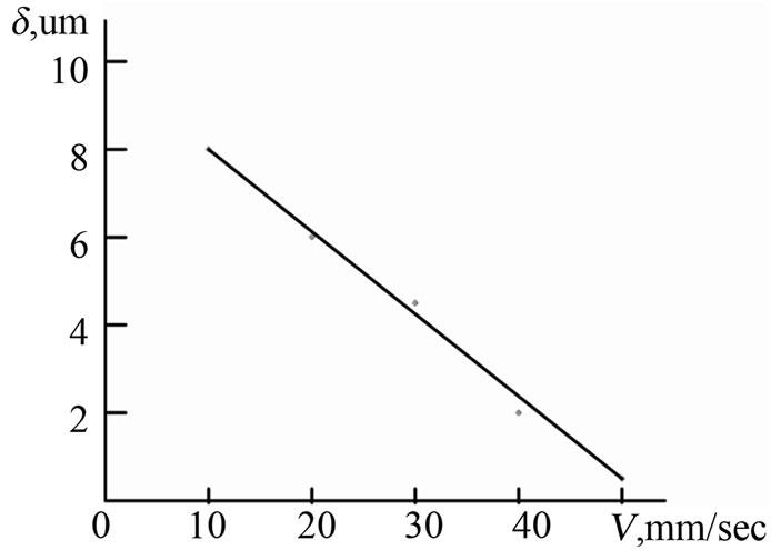
Figure 2. The dependence of the line’s (microcrack) width d from the feed rate V when LCT method.
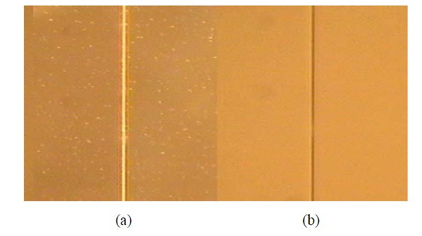
Figure 3. Microcrack view is with backlight (a) and without backlight (b).
Figure 4 shows results of microcrack geometrical parameters measurements filled by a phosphor that was measured on the tunnel microscope Supra 50 VP LEO.
The main advantage of developed technology in that the production of grid lines is the single technological cycle, i.e. following etching and line painting is not required (as for the mechanical method) and there are no complex technological processes (as for the photolithography). The speed of the line making is a few hundred millimeters per second.
An important advantage of this method is that practically any material can be put into the microcrack (in the form of fine particles) with required optical properties, without worrying about the presence or absence of adhesion to a glass.
For some of optical devices, in particular, night vision devices, one of the main requirements is to ensure the visibility of the grid lines on a dark background. The part of light is scattered on the glass surface and smallest defects (if it there are) at the common backlight. It gives a common light background that confuses the outlook. In
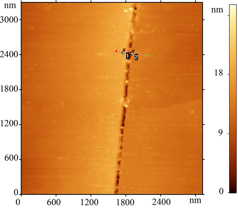
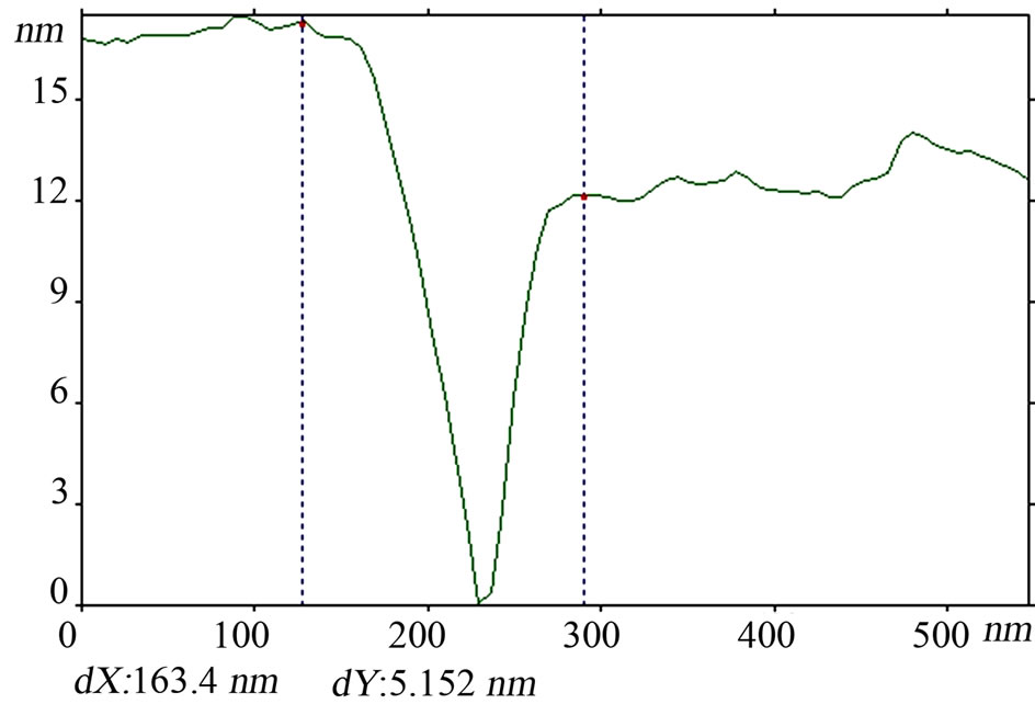
Figure 4. Results are measurements of geometrical parameters of microcrack filled by a phosphor. Measuring equipment is the tunnel microscope Supra 50 VP LEO.
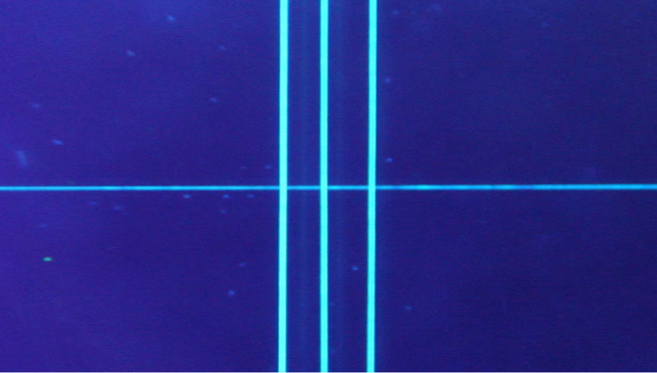
these cases an effective solution is luminescent lines making, which lets be highlighted by ultraviolet light that is invisible for the human eye (Figure 5(a)). Manufacturing of such lines by traditional methods is difficult because not all of phosphors have a good adhesion to a glass. Using the LCT method, this kind of the problem doesn’t arise. Various phosphors (including organic) can be successfully used with the possibility of obtaining different lines colors and backlight in the different spectral range (Figure 5(b)). Varying by phosphor concentration in the coolant, it gives lines with a different intensity of the glow. The width of the grid lines is only a few hundredths of a micron but they are clearly visible as clear luminous lines, both as in case of magnification and with the naked eye.
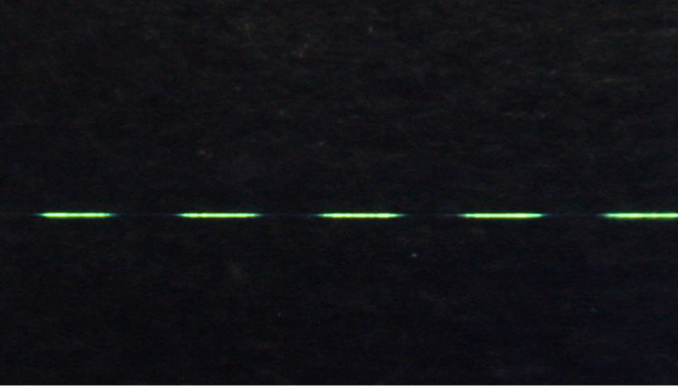
It should be noted that the described method for optical line application is not limited for continuous lines. Figure 6 shows photos of the dash line (a) and dash quintuple-dot line (b) that was obtained by the LCT method. It is available to make many kinds of linetypes depending on the request.
3. Conclusions
The new high-effective method allows to obtain optical tags: Line, mark, risk, grid, etc. with the set of geometrical parameters that impossible to get using conventional technologies.
In addition, the described method [5] provides the possibility to make wiring in the glass (for instance) filling
 (a)
(a)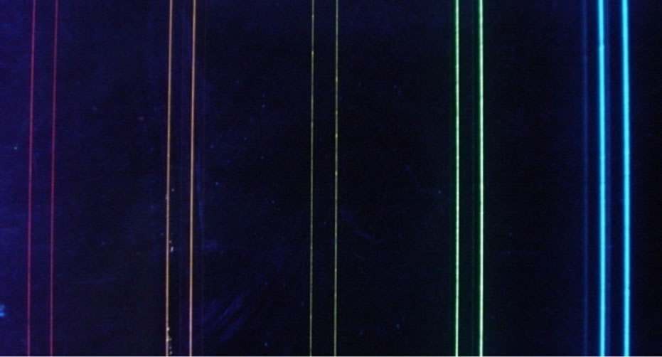 (b)
(b)
Figure 5. Luminous lines of blue (a) and different colors (b).
 (a)
(a)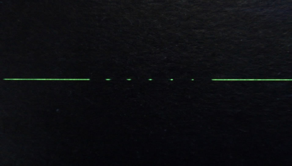 (b)
(b)
Figure 6. The dash line (a) and dash quintuple-dot line (b) photos obtained by the LCT method.
the microcrack by metal current-conducting nanopowders and it provides to get glowing grooves using luminescent compounds. It can be widely used in the building market, for some new generation devices and products.
The fulfilled complex of works in fundamental and applied research of the LCT method shows the competitiveness of the Russian scientific school in the field of high technologies.
Many researches in this paper were done in accordance with the Government Decree of the Russian Federation No. 218, dated 9 April, 2010, on the basis of a Contract 13. G25. 31.0020 between the Ministry of Education and Science of the Russian Federation and JSC “MZ ‘Sapphire’” in creation of hi-tech production manufacturing.
REFERENCES
- L. M. Krivoviaz, D. T. Puriaev and M. A. Znamenskaya, “The Practice of Optical Measuring Laboratory,” Machinery, Moscow, 2004, 333 p.
- V. S. Kondratenko, “Method of Cutting of Brittle Material,” the Patent of Russian Federation, No. 2024441, 1991.
- I. V. Golubjatnikov, V. S. Kondratenko and A. B. Zhymalov, “Development of the Theory and Practice of a Method Laser Controlled Thermocracking,” Instruments, Vol. 12, No. 114, 2012, pp. 1-6.
- V. S. Kondratenko, V. I. Gundiak and V. Y. Bersenyev, “Application of the Method of Laser Controlled Thermocracking of a Glass in the Production of Optical Parts— Electronic Engineering, Ser,” Laser Technology and Optoelectronics, Ser. Electronic Engineering, Vol. 4, No. 56, 1990, pp. 70-71.
- V. S. Kondratenko, “Method of Cutting of Brittle NonMetallic Materials (Two Variants),” The Patent of Russian Federation, No. 2333163, 2007.