World Journal of Nuclear Science and Technology
Vol.1 No.2(2011), Article ID:6476,7 pages DOI:10.4236/wjnst.2011.12009
Determination of Neutron Fluxes and Spectrum Shaping Factors in Irradiation Sites of Ghana’s Miniature Neutron Source Reactor (mnsr) by Activation Method after Compensation of Loss of Excess Reactivty
1School of Nuclear and Allied Science, University of Ghana, Atomic Energy, Accra, Ghana
2Ghana Atomic Energy Commission, National Nuclear Research Institute, Legon, Ghana
E-mail: *robertmauko@yahoo.com
Received March 21, 2011; revised April 20, 2011; accepted May 27, 2011
Keywords: Fluence Rate, Foil Activation, Neutron Self-Shielding, Flux Ratio
Abstract
Accurate neutron flux values in irradiation channels of research reactors are very essential to their usage. The total neutron flux of the Ghana Research Reactor-1 (GHARR-1) was measured after a beryllium reflector was added to its shim to compensate for excess reactivity loss. The thermal, epithermal and fast neutron fluxes were determined by the method of foil activation. The experimental samples with and without a cadmium cover of 1-mm thickness were irradiated in the isotropic neutron field of the irradiation sites of Ghana Research Reactor-1 facility. The induced activities in the sample were measured by gamma ray spectrometry with a high purity germanium detector. The necessary correction for gamma attenuation, thermal neutrons and resonance neutron self-shielding effects were taken into account during the experimental analysis. By defining cadmium cutoff energy of 0.55 eV, Al-0.1% Au wires of negligible thickness were irradiated at 3 kW to determine the neutron fluxes of two irradiation channels, outer channel 7 and inner channel 2 whose Neutron Shaping Factor (α) were found to be (0.037 ± 0.001) and (–0.961 ± 0.034). The neutron flux ratios at the inner irradiation site 2 were found to be, (25.308 ± 3.201) for thermal to epithermal neutrons flux, (0.179 ± 0.021) for epithermal to fast neutrons flux and (4.528 ± 0.524) for thermal to fast neutrons flux, in the outer irradiation site 7, the neutron flux ratios were found to be, (40.865 ± 3.622) for thermal to epithermal neutrons flux, (0.286 ± 0.025) for epithermal to fast neutrons flux and (11.680 ± 1.030) for thermal to fast neutrons flux.
1. Introduction
Neutrons are readily obtained by the action of alpha particles on some light elements, example, beryllium, boron, or lithium. Neutrons have high energies covering a wide range, example, from 1 MeV to 10 MeV or more. The sources are thus said to be polyenergetic [1].
Many of the techniques for production of homogeneous neutrons are also used in neutron energy measurement. The most important source of thermal neutrons is the nuclear reactor [2].
The inner irradiation sites in the research reactor are usually used to irradiate and analyze unknown samples, using the neutron activation technique through (n, γ) thermal neutron reactions. The inner irradiation site in the MNSR contains both the fast and the thermal neutron fluxes.
The Ghana Research Reactor-1 (GHARR-1) is specifically designed for use in neutron activation analysis (NAA) and isotope production; therefore there is need for a careful and complete characterization of the neutron flux parameters in the irradiation channels in order to optimize its utilization for NAA via relative, absolute and single comparator methods. Low-power research reactors such as the Canadian Slowpoke and the Chinese MNSR, which run on the same fuel loading for over ten years, are known to exhibit stable neutron flux characteristics (Figure 1).
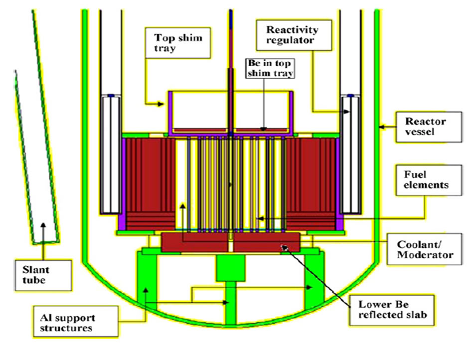
Figure 1. MCNP plot of vertical cross section of GHARR-1 reactor (control rod in full withdrawn position) showing structural supports [3].
Design Considerations of Ghana Research Reactor-1 (GHARR-1)
The Ghana Research Reactor-1 (GHARR-1) which is a 30 kW tank-in-pool reactor, which uses 90.2% enriched uranium-Al alloy as fuel. Detail description of GHARR-1 can be found in Sogbadji et al., 2010 [4].
2. Theory
The nuclei of certain naturally occurring isotopes can be transformed into radioactive ones by exposing the material to neutron radiation, and the activity of the radioactive products produced can be measured by means of appropriate counter system. In addition to the factors determined by the conditions of measurement, this activity is affected only by the neutron flux in the point of irradiation and by the activation cross section of the target material which in the present case is the neutron detector. Provided the activation cross section is known, the neutron flux can be determined by measurement of the activity of the sample irradiated [1].
Thermal neutron fluence rate determination The equivalent 2200 m/s thermal fluence rate  , in which Au is irradiated and used as a monitor can be calculated as
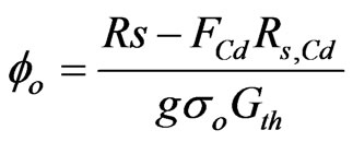 (1)
(1)
where Rs and Rs,Cd are the reaction rate per atom of bare and Cd-covered isotope irradiation, g is the correction for departure from cross-section behavior, Gth the selfshielding factor for thermal neutrons, σo the thermal neutron cross-section, and FCd the cadmium correction factor [5]; Rs and Rs,Cd are determined by the equation
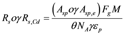 (2)
(2)
with
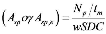 (3)
(3)
where Asp, Asp,e are the specific activities obtained after a bare and cadmium covered isotope irradiation, Np the net number of counts under the full-energy peak collected during measuring time, tm , w the weight of irradiated element,  the saturation factor with λ being the decay constant, tirr the irradiation time,
  the decay factor with td being the decay time,
the measurement factor correcting for decay during the measuring time, tm , M the atomic weight, θ, the isotopic abundance, NA the Avogadro’s number, γ the absolute gamma-ray emission probability, p the full-energy peak detection efficiency, and Fg the correction factor for gamma-ray attenuation [5].
The correction factor for gamma-ray attenuation in the sample at a given gamma-ray energy at a fixed geometry for the case a cylinder, coaxially positioned with the detector, is given by
 (4)
(4)
where  is the linear attenuation coefficient (cm−1),
  is the total mass attenuation coefficient (cm2/g) for the compounds used. ρ is the density of sample (g/cm3) and x is the sample thickness (in cm) [5].
Epithermal neutron fluence rate determination.
In a mixed thermal and  epithermal neutron field, the epithermal neutrons fluence rate per unit
  of neutron energy interval can be calculated by
 (5)
(5)
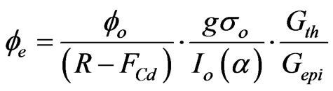
where R is the cadmium ratio defined by,  ,
,  the resonance integral cross-section, including contribution, characterized by epithermal neutron spectrum shaping factor, which is energy dependent, and Gepi the self-shielding factor for epithermal neutrons [5].
Fast neutron fluence rate determination The fast neutron flux is usually defined by (IAEA, 1970) as
 (6)
(6)
It is well known that the rate of change of radioactive atoms produced by the irradiation in the activation (production) rate minus the decay rate, as in Equation (4). The activation rate of fast neutron flux is given by the equation
 (7)
(7)
here
 (8)
(8)
NT is the total number of the nuclides of interest in the target [6]. By making  the subject in Equation (7) and replacing the activity by the activity Equation (3), the equation to determine the fast neutron was derived as follows;
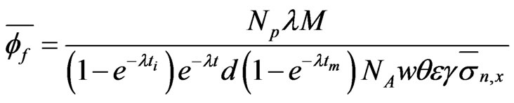 (9)
(9)
where Np is the net peak counts under gamma line of interest, M is the atomic mass of target nucleus, NA is the Avogadro’s number, θ is the isotopic abundance of target nucleus, γ is the gamma-ray abundance of residual radionuclide, λ is the decay constant, ti is the irradiation time, tm is the measuring time, tc is the cooling time, ε is the full energy peak efficiency, w is the mass of target isotope in sample,  is the threshold reaction fission spectrum averaged cross section of 27Al(n, p)27Mg which is 4.00 mb [7] and
  is the fast neutron flux [6].
Determination of Neutron Shaping Factor (α)
For non-ideal reactor situation, the resonance integral, Io, needs to be modified with an α-dependent term because the Io values, which are valid only for ideal spectra, is not true for a deviating spectra [8].
For the non-ideal conditions Io(α) values ought to be used instead of Io. The conversion of Io to α-dependent terms takes the form [9]:
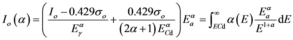
where  = effective resonance energy,
  = l eV— arbitrary energy,
  = 0.55 eV—effective cadmium cut-off energy,
  = 2200 ms−1 (n, γ) Cross section and α = an experimentally determinable characteristics of the reactor channel. Although the epithermal neutrons represent only a small fraction of the total reactor neutrons, they are sometimes useful in NAA for several elements (e.g. Br, Kb, Sr, Mo, Ba, Ta and U) that have higher relative reaction rates for epithermal neutrons than for thermal neutrons. The technique of taking advantage of those (n, γ) reactions with high resonance integrals through the irradiation of samples under a cadmium cover to shield out the thermal neutrons is commonly known as Epithermal Neutron Activation Analysis (ENAA).
The large number of resonance peaks for most nuclides makes a calculation of effective cross sections for the epithermal neutrons slightly complicated. In order to avoid these resonances, a gold standard is used because the reaction 197Au (n, γ) 198Au has a single resonance (411 KeV) peak and it has been well investigated [10,11] and found to be 1550 barns. The activity ratio for an infinitely thin gold foil or alloy irradiated with and without cadmium covers (Cadmium ratio method) is used [12] for measuring epithermal flux-shaping factor and thermal to epithermal flux ratio. This method is also used as a calibration standard to measure the resonance integrals for (n, γ) reactions [9].
If the single comparator technique is adopted for routine NAA, the effect of the non-ideal epithermal spectrum should not be neglected. Thus, to be accurate in all relevant expressions, Qo should be replaced by Qo(α) (where Qo(α) is the α-corrected Qo to take care of the non-ideality of the epithermal spectrum)
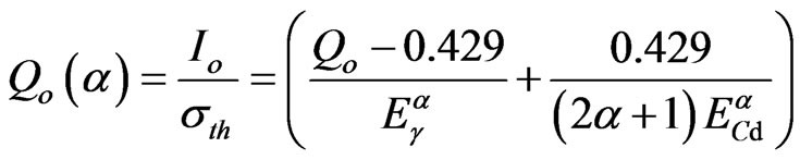
where Qo is the ratio of resonance is integral to thermal cross-section is given as  which is related to flux ratio, f, as
Experimental determination of α, using the cadmium ratio method involves irradiating two or more monitors (e.g. Au, Zr, Co) with and without cadmium alternately at the same irradiation channel [13].
When monitors such as 197Au and 94Zr are irradiated under uniform neutron flux, it transforms to
The epithermal deviation factor is obtained from it using iteration method by using computer programming language such C++ or Fortran which produces more accurate results.
3. Experimental
Flux Determination by the Activation Method Two irradiation channels were chosen for the measurement, one outer channel, site 7, and one inner channel, site 2. These channels were chosen at random.
In the determination of the neutron fluxes at the outer and inner irradiation sites, 7 and 2 respectively, Al-0.1%Au alloy wires were used as the flux monitors. The samples (Al-0.1%Au alloy wires) to be activated were put in the polyethylene vials with 1 mm wall thickness and internal diameter of the tube is 15.0 mm. The polyethylene vials were stuffed with cotton to make it weighty and heat sealed. They were exposed to the neutrons in a fixed position in the irradiation channels of a larger volume compared to the sample volume via a pneumatic system. Therefore, the effect of thermal fluence depression at the irradiation site is neglected.
The irradiations of the samples were carried out within and without a cylindrical cadmium shield case at the outer and inner irradiation channels, 7 and 2 respectively. Since 27Al isotope has low neutron absorption crosssection. Ten samples were irradiated in irradiation channels considered, four each for thermal neutrons and cadmium shielded for epithermal neutrons and the last two samples also cadmium covered for fast neutrons. The irradiation times of the (n, γ) reactions of the Al-0.1%Au wire were carefully chosen yielding enough activity to be measured in γ-ray counting system. The suitable waiting times were employed to minimize dead time losses.
The irradiation for thermal and epithermal neutron flux monitoring were performed for 1 hour, and 5 minutes for fast neutron flux in the inner irradiation channel 2. In the outer irradiation channel 7, the irradiation for thermal and epithermal neutron flux monitoring were performed for 1 hour, and 10 minutes for fast neutron flux.
The use of Al-0.1%Au foil for the irradiation under cadmium shield permits the monitoring of the fast neutron flux via the 27Al (n, p) 27Mg reaction and the epithermal neutron flux via the 197Au (n, γ) 198Au reaction simultaneously. The use of a bare Al-0.1%Au foil for the irradiation permits the monitoring of the thermal neutron flux via the 197Au (n, γ) 198Au reaction. All irradiations were performed at a thermal power level of 3kW, which corresponds to a thermal neutron flux value of 1.0 × 1011 cm−2·s−1 preset on the control console. After the irradiation, induced radioactivity in detector foils were counted on a HPGe coaxial detector (ORTEC), which has a relative efficiency of 25% and energy resolution of 1.8 KeV at 1332.5 KeV gamma-ray of 60Co was used for the measurement [14]. The full-peak energy efficiency parameter of the detector has been determined by standard gamma ray sources by fitting the efficiency curve with a polynomial function using parameters determined earlier [14]. The gamma-ray acquisition system consists of MAESTRO Multi-Channel Analyzer (MCA) emulation software card, coupled to the detector via electronic modules.
In Equations, the thermal, epithermal and fast neutron fluxes respectively are deduced relative to the spectrum averaged cross section data.
Determination of Neutron Shaping Factor (α)
In the determination of the Neutron Shaping Factor (α) at the outer and inner irradiation sites, 7 and 2 respectively, Al-0.1%Au alloy wires and zirconium foils were used. The samples (Al-0.1%Au alloy wires and zirconium foils) to be activated were put in the polyethylene vials with 1 mm wall thickness and internal diameter of the tube is 15.0 mm. The polyethylene vials were stuffed with cotton to make it weighty and heat sealed. They are exposed to the neutrons in a fixed position in the irradiation channels of a larger volume compared to the sample volume. Therefore, the effect of thermal fluence depression at the irradiation site is neglected.
The irradiations of the samples were carried out within and without a cylindrical cadmium shield case at the outer and inner irradiation channels, 7 and 2 respectively. The irradiation times of the (n, γ) reactions of the Al-0.1Au wire and zirconium foils were carefully chosen yielding enough activity to be measured in γ-ray counting system. The suitable waiting times were employed to minimize dead time losses (Figure 2).
The irradiation was performed for 1hour at the entire irradiation channel (i.e. 7 and 2). The use of Al-0.1%Au foil for the irradiation under cadmium shield permits the monitoring of the cadmium ratio of gold via the reaction 197Au (n, γ) 198Au. The use of zirconium foil for the irradiation under cadmium shield permits the monitoring of the cadmium ration of gold via the reaction 95Zr (n, γ) 96Zr. After the irradiation, induced radioactivity in detector foils were counted on the HPGe coaxial detector.
4. Results and Discussion
The results of the measurements of the thermal, epithermal and fast neutron fluxes, and the Neutron Shaping Factor (α), carried out in this study and the ones reported earlier by other authors are presented and discussed below.
The determination of neutron fluxes in an irradiation channel is necessary to monitor the continuous stability of the nuclear reactor flux (required for neutron activation analysis), characterize a new channel and re-characterize an old channel [15] after refueling and/or core configuration change [16].
Experimental determination of thermal to epithermal flux is achieved via cadmium ratio or the bare monitor method [17]. The results obtained for this work and for similar work performed on the same reactor are presented in Table 1.
All neutron flux measurement was done at 3 kW, with the console recording a flux of 1 × 1011 cm−2·s−1, at 30 kW (full power) the reactor console records a neutron flux value of 1 × 1012 cm−2·s−1. This implies that the experimental flux values obtained at 3 kW could be estimated at 30 kW (full power) by multiplying the neutron fluxes at 3 kW with a factor of 10.
These estimated neutron flux values at 30 kW are shown in Table 2 and the neutron flux ratios are shown in Table 1.
The results tabulated in Table 1 show that at the inner channel 2 being considered, thermal fluxes were high, followed by the fast neutron flux neutrons and then the epithermal, but in the outer irradiation channel 7 the fast neutron flux is less than the epithermal in that channel, though thermal neutrons still exhibit the highest neutron flux in that channel. However, the flux ratios of the thermal to epithermal neutron fluxes in both outer and inner irradiation channels are comparable within error to flux ratios values obtained by Y. A. Ahmed et al. in 2006 on the same reactor [17]. The fast neutron flux measured at the outer irradiation channel 7 is very low as compared to the thermal flux at the same channel; this is due to neutron moderation by the annulus beryllium around the reactor core. At the inner irradiation channel 2 the fast
Figure 2. MCNP5 plot of GHARR-1 core configuration showing fuel region (reactor core), channels for irradiation, fission chamber, regulating rods, and annular beryllium reflector [3].
Table 1. Measured neutron flux ratios of the inner 2 and outer 7 irradiation channel at 3 kW
Table 2. Estimated neutron flux values of the inner 2 and outer 7 irradiation channel at 30 kW
neutron flux shows an appreciable amount which is in good agreement with WIMSD4 code measurement made by K. Khattab in 2005 [6]. This shows that there has not been any significant change to the neutron fluxes at the irradiation sites being considered since a beryllium plate was added to the top shim tray.
Neutron Shaping Factor (α) in the Irradiation Channels Among the various experimental methods available for determining the Neutron Shaping Factor (α), the cadmium ratio method is known to yield the most accurate results. Determination of the shaping factor in this study was carried out using the cadmium ratio method.
In general, the neutron spectrum parameters α obtained in this work for the irradiation channels of GHARR-1 being considered compares very well with the α values obtained by Akaho et al. on the same reactor in 2002 [18].
The measured α values for the outer irradiation channel of GHARR-1 used compares very well with the Nigeria Research Reactor-1 (NIRR-1) which is also an MNSR similar to GHARR-1, but α values for the outer irradiation channel of GHARR-1 used deviates significantly when compared with that of NIRR-1. In order to ascertain the source of the deviation, the values of the cadmium ratios, RCd, of the isotopes used (94Zr and 197Au) were considered since that of NIRR-1 could be found in other journals.
This was done because both reactors with similar fuel are believed to have identical neutron spectra. It was discovered that the difference may be due to the cadmium ratio value of 197Au, RCd (Au), which is 2.36 determined in the work and is comparable to the work by Akaho et al. on the same reactor in 2002 [18-24] who had a cadmium ratio value of 197Au, RCd (Au) for 2.36, which is not in good comparison with the result of 2.12 for NIRR-1 [7]. Even though these reactors are identical, this is possible due the fact that the two reactors have slightly different number of fuel pins, hence affecting the of fuel volume-moderator volume ratio.
5. Conclusions
By using the Al-0.1%Au wire to measure the thermal, epithermal and fast neutron fluxes of the Ghana Research Reactor-1 (GHARR-1), the fluxes obtained in this work (as shown in Tables 1 and 2) are in good agreement with the neutron flux values obtained when the reactor was less than five (5) years old.
This shows that the miniature neutron source reactor, design by the Chinese, has good neutron flux stability over long periods of time since the GHARR-1 has been in operation for more than ten (10) years. This has also been confirmed by the Neutron Shaping Factor (α) obtained in this work since the shaping factor (α) of the irradiation channels considered in this work has not change significantly over the years.
In this thesis work, the shaping factor (α) was measured using the cadmium ratios of zirconium-95 and gold-198 coupled with an iterative computer program written in Fortran 90 for Equation (17), but this parameter, (α), could also be measured using the graphical method [22]. If this method is used in further researches, it will ascertain the results obtained in this work. I also recommend that other methods, such as the cadmium ratio method should be used to measure and confirm neutron flux ratios obtained at the irradiation channels used in this work.
6. References
[1] S. Glasstone and A. Sesonske, “Nuclear Reactor Engineering: Reactor Design Basics,” Kluwer Academic Publishers, Norwell, 1994, pp. 59-71, 77-79.
[2] W. E. Burcahm, “Nuclear Physics, an Introduction,” Longman, London, 1970, pp. 12-15, 25-28.
[3] S. Anim-Sampong, B. T. Maakuu, E. H. K. Akaho, A. Andam, J. J. R. Liaw and J. E. Matos, “Progress in the Neutronic Core Conversion (HEU-LEU) Analysis of Ghana Research Reactor-1,” 2006 International RERTR Meeting, Cape Town, 29 October- 2 November 2006, pp. 6-7.
[4] R. B. M. Sogbadji, et al., Nuclear Engineering and Design, Vol. 240, 2010, pp. 980-984. doi:10.1016/j.nucengdes.2009.12.020
[5] G. I. Bell and S. Glasstone, “Nuclear Reactor Theory,” Chapter 7, Van Nostrand Reinhold, New York, 1970.
[6] E. H. K. Akaho and B. J. B. Nyarko, “Characterization of Neutron Flux Spectra in Irradiation Sites of MNSR Reactor Using the Westcott-Formalism for the Ko Neutron Activation Analysis Method,” 2002, p. 268.
[7] M. Karandag, H. Yücel, M. Tan and A. Özmen, “Measurement of Thermal Neutrons and Resonance Integral for 71Ga(N,Γ) 72Ga and 75As (N, Γ) 76As by Using 241Am-Be Isotopic Neutron Source,” 2003, pp. 524-527.
[8] K. Khattab, “Measurement of Fast Neutron Flux in the MNSR Inner Irradiation Site,” Applied Radiation and Isotopes, Vol. 65, No. 1, 2005, pp. 46-48. doi:10.1016/j.apradiso.2005.11.020
[9] T. Elnimr and I. I. Bondouk, “The Use of Ke,0 Factors as a Tool for a Critical Evaluation of Reactor Thermal and Epithermal (N, Γ) Cross-Section and of Absolute Gamma Intensities,” 1983, pp. 1409-1414.
[10] F. De Corte, A. De Wispelaere and L. Hoste, “Accuracy and Applicability of ko Method,” Journal of Radioanalytical Chemistry, Vol. 113, No. 1, 1987, pp. 145-161. doi:10.1007/BF02036056
[11] G. Kennedy, J. St. Pierre, K. Wang, Y. Zang, J. Preston and C. V. Grant, “Activation Constant of SLOWPOKE and MNSR Reactors Calculated from the Neutron Spectrum and Ko and Qo Values,” Journal of Radioanalytical Chemistry, Vol. 245, No. 1, 2000, pp. 167-172. doi:10.1023/A:1006749820638
[12] E. H. K. Akaho and B. J. B. Nyarko, “Characterization of Neutron Flux Spectra in Irradiation Channels of MNSR Reactor, Using Wescott-Formalism for the Ko Neutron Activation Analysis,” Applied Radiation and Isotopes, 2002, pp 265-273. doi:10.1016/S0969-8043(02)00106-9
[13] F. De Corte, K. S. Hammami, L. Moens, A. Simonits, A. De Wispelaere and J. Hoste, “The Accuracy of the Experimental Alpha-Determination in the Epithermal Reactor Neutron Spectrum,” Journal of Radioanalytical Chemistry, Vol. 62, No. 1-2, 1981, pp. 209-255. doi:10.1007/BF02517354
[14] E. K. Osae, B. J. B. Nyarko, Y. Serfor-Armah and E. O. Darko, “An Empirical Expression for the Full Energy Peak Efficiency of an N-Type High Purity Germanium Detector,” Journal of Radioanalytical and Nuclear Chemistry, Vol. 242, No. 3, 1999, pp. 618-619. doi:10.1007/BF02347370
[15] F. De Corte and A. De Wispelaere, “Recalibration of the Irradiation Facilities in the Thesis Reactor with an Examination of the Α versus E Behavior in Kev Neutron Energy Range,” Vol. 257, No. 3, 2003, pp. 519-523.
[16] C. O. Mustra, M. C. Freitas and S. M. Almeida, “Neutron Flux and Associated Ko Parameters in the RPI after the Last Configuration Change,” Journal of Radioanalytical and Nuclear, Vol. 257, No. 3, 2003, pp. 539-543. doi:10.1023/A:1025432329915
[17] Y. A. Ahmed, I. O. B. Ewa, I. M. Umar, T. Bezborah, M. Johri and E. H. K. Akaho, “The Low Power Miniature Neutron Source Reactors: Design, Safety and Applications,” The Abdus Salam International Centre for Theoretical Physics, Trieste, 2006.
[18] S. A. Jonah, G. I. Balogun, I. M. Umar and M. C. Mayaki, “Neutron Spectrum Parameters in Irradiation Channel of the Nigeria Research Reactor-1(NNRI-1) for the KoNAA Standardization,” Journal of Radioanalytical and Nuclear Chemistry, Vol. 266, No. 1, 2005, pp. 83-88. doi:10.1007/s10967-005-0873-8
[19] S. A. Jonah, G. I. Balogun, I. M. Umar and M. C. Mayaki, “Neutron Spectrum Parameters in Irradiation Channels of the Nigeria Research Reactor-1 (NIRR-1) for the K0- NAA Standardization,” Journal of Radioanalytical and Nuclear Chemistry, Vol. 266, No. 1, 2004, pp. 82-85.
[20] L. Moen, F. De Corte, A. Simonits, A. Wispelaere and J. Hoste, “The Effective Resonance Energy Er as a Parameter for the Correction of Resonance Integrals, 1/E(1+ Α) Epithermal Neutron Spectra: Tabulation of Er for 96 Isotopes,” Journal of Radioanalytical Chemistry, Vol. 52, No. 2, 1979, pp. 379-387. doi:10.1007/BF02521289
[21] S. Jovanovic, P. Vukotic, R. Jacimovic, N. Mihaljevic and P. Stegnar, “Epithermal Neutron Flux Characterization of the TRIGA II Reactor, Ljugljana, Yugoslavia for Use in NAA,” Journal of Radioanalytical Chemistry, Vol. 113, No. 1, 1989, pp. 177-185.
[22] R. G. Nisle, “A Unified Formulation of the Specification of Neutron Flux Spectra in Reactors, Neutron Dosimetry,” IAEA-TECH Report 1. 1963, pp. 111-152.
[23] R. F. Fleming, International Journal of Applied Radiation and Isotopes, Vol. 33, 1982, p. 1263. doi:10.1016/0020-708X(82)90247-2
[24] M. Abramowitz, I. A. Stegun, “Handbook of Mathematical Functions US,” Government Printing Office, Washington, DC, 1964.