Paper Menu >>
Journal Menu >>
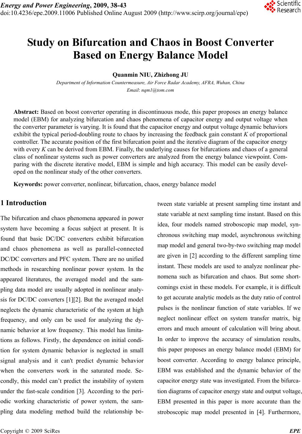 Energy and Power Engineering, 2009, 38-43 doi:10.4236/epe.2009.11006 Published Online August 2009 (http://www.scirp.org/journal/epe) Copyright © 2009 SciRes EPE Study on Bifurcation and Chaos in Boost Converter Based on Energy Balance Model Quanmin NIU, Zhizhong JU Department of Information Countermeasure, Air Force Radar Academy, AFRA, Wuhan, China Email: nqm1@tom.com Abstract: Based on boost converter operating in discontinuous mode, this paper proposes an energy balance model (EBM) for analyzing bifurcation and chaos phenomena of capacitor energy and output voltage when the converter parameter is varying. It is found that the capacitor energy and output voltage dynamic behaviors exhibit the typical period-doubling route to chaos by increasing the feedback gain constant K of proportional controller. The accurate position of the first bifurcation point and the iterative diagram of the capacitor energy with every K can be derived from EBM. Finally, the underlying causes for bifurcations and chaos of a general class of nonlinear systems such as power converters are analyzed from the energy balance viewpoint. Com- paring with the discrete iterative model, EBM is simple and high accuracy. This model can be easily devel- oped on the nonlinear study of the other converters. Keywords: power converter, nonlinear, bifurcation, chaos, energy balance model 1 Introduction The bifurcation and chaos phenomena appeared in power system have becoming a focus subject at present. It is found that basic DC/DC converters exhibit bifurcation and chaos phenomena as well as parallel-connected DC/DC converters and PFC system. There are no unified methods in researching nonlinear power system. In the appeared literatures, the averaged model and the sam- pling data model are usually adopted in nonlinear analy- sis for DC/DC converters [1][2]. But the averaged model neglects the dynamic characteristic of the system at high frequency, and only can be used for analyzing the dy- namic behavior at low frequency. This model has limita- tions as follows. Firstly, the dependence on initial condi- tion for system dynamic behavior is neglected in small signal analysis and it can't predict dynamic behavior when the converters work in the saturated mode. Se- condly, this model can’t predict the instability of system under the fast-scale condition [3]. According to the peri- odic working characteristic of power system, the sam- pling data modeling method build the relationship be- tween state variable at present sampling time instant and state variable at next sampling time instant. Based on this idea, four models named stroboscopic map model, syn- chronous switching map model, asynchronous switching map model and general two-by-two switching map model are given in [2] according to the different sampling time instant. These models are used to analyze nonlinear phe- nomena such as bifurcation and chaos. But some short- comings exist in these models. For example, it is difficult to get accurate analytic models as the duty ratio of control pulses is the nonlinear function of state variables. If we neglect nonlinear effect on system transfer matrix, big errors and much amount of calculation will bring about. In order to improve the accuracy of simulation results, this paper proposes an energy balance model (EBM) for boost converter. According to energy balance principle, EBM was established and the dynamic behavior of the capacitor energy state was investigated. From the bifurca- tion diagrams of capacitor energy state and output voltage, EBM presented in this paper is more accurate than the stroboscopic map model presented in [4]. Furthermore, 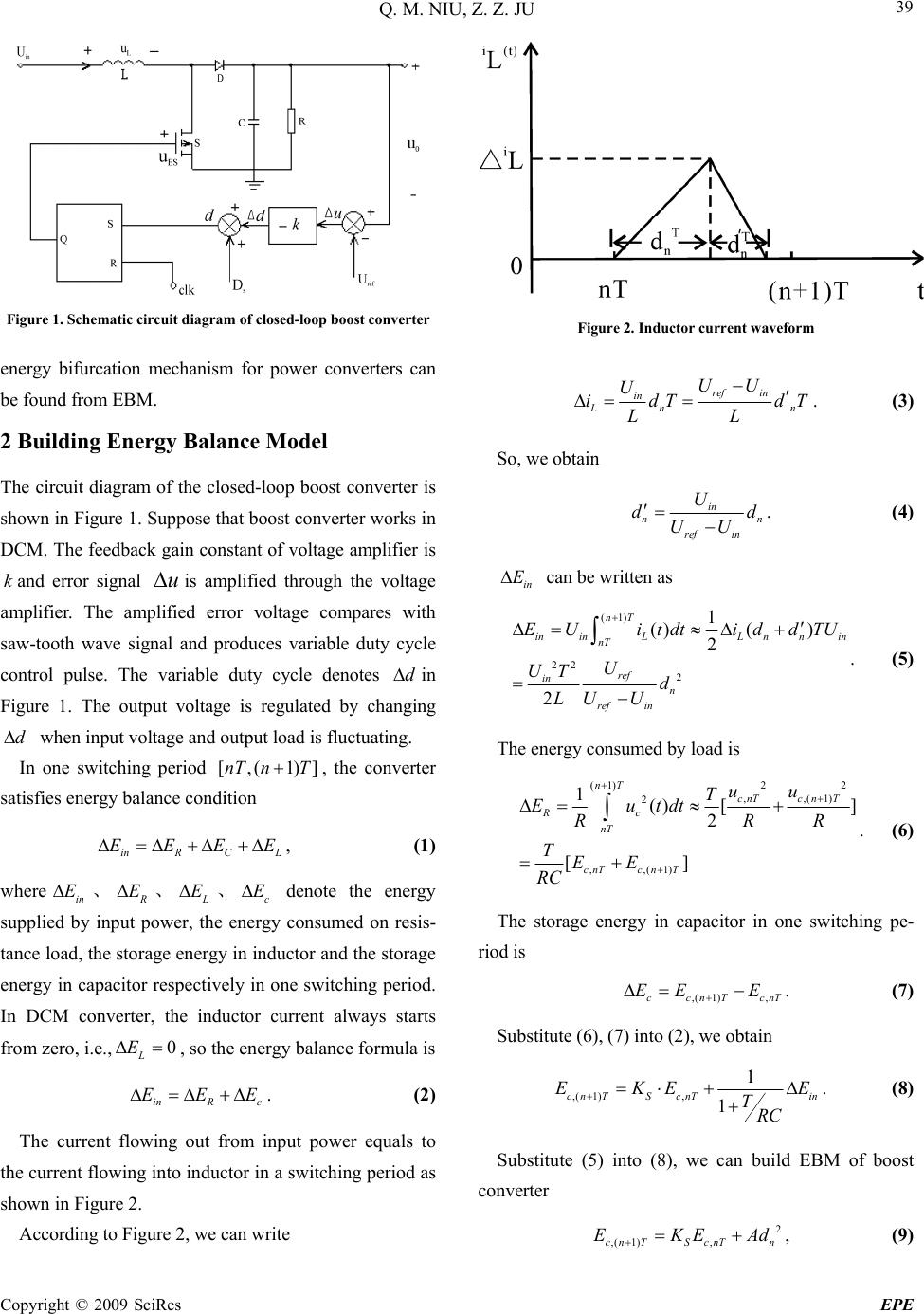 Q. M. NIU, Z. Z. JU Copyright © 2009 SciRes EPE 39 Figure 1. Schematic circuit diagram of closed-loop boost converter energy bifurcation mechanism for power converters can be found from EBM. 2 Building Energy Balance Model The circuit diagram of the closed-loop boost converter is shown in Figure 1. Suppose that boost converter works in DCM. The feedback gain constant of voltage amplifier is and error signal is amplified through the voltage amplifier. The amplified error voltage compares with saw-tooth wave signal and produces variable duty cycle control pulse. The variable duty cycle denotes ku d in Figure 1. The output voltage is regulated by changing when input voltage and output load is fluctuating. d In one switching period , the converter satisfies energy balance condition [,( 1)]nT nT inR CL EEEE, (1) where、 in E R E、 L E、c E denote the energy supplied by input power, the energy consumed on resis- tance load, the storage energy in inductor and the storage energy in capacitor respectively in one switching period. In DCM converter, the inductor current always starts from zero, i.e.,, so the energy balance formula is 0 L E inR c EEE. (2) The current flowing out from input power equals to the current flowing into inductor in a switching period as shown in Figure 2. According to Figure 2, we can write Figure 2. Inductor current waveform ref in in Ln UU U idT d LL n T . (3) So, we obtain in n ref in U d UU n d . (4) in E can be written as (1) 22 2 1 ()( ) 2 2 nT ininLL nnin nT ref in n ref in EUitdt iddTU U UT d LU U . (5) The energy consumed by load is 2 2 (1) ,( 1) , 2 ,,(1) 1() [] 2 [] nT cn T cnT Rc nT cnTc nT u u T Eutdt RR TEE RC R T . (6) The storage energy in capacitor in one switching pe- riod is ,( 1),ccnTcn EE E . (7) Substitute (6), (7) into (2), we obtain ,( 1), 1 1 cn TScnTin EKETRC E . (8) Substitute (5) into (8), we can build EBM of boost converter 2 ,( 1),cnTScnTn EKEA d, (9) 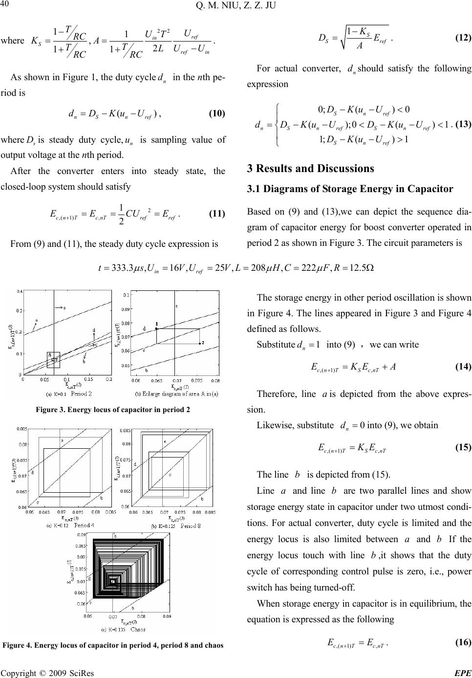 Q. M. NIU, Z. Z. JU Copyright © 2009 SciRes EPE 40 where 1 1 S TRC KTRC , 22 1 2 1 ref in ref in U UT ATLU U RC . 1S S K D A r ef E 1 . (12) For actual converter, should satisfy the following expression n d As shown in Figure 1, the duty cycle in the nth pe- riod is n d 0;() 0 ();0 () 1;()1 Snref nS nrefS nref Snref DKuU dDKu UDKu U DKuU . (13) ( nS nref dDKuU ), (10) where s Dis steady duty cycle, is sampling value of output voltage at the nth period. n u 3 Results and Discussions After the converter enters into steady state, the closed-loop system should satisfy 3.1 Diagrams of Storage Energy in Capacitor 2 ,( 1), 1 2 cn TcnTrefref EECU Based on (9) and (13),we can depict the sequence dia- gram of capacitor energy for boost converter operated in period 2 as shown in Figure 3. The circuit parameters is E. (11) From (9) and (11), the steady duty cycle expression is 333.3,16 ,25 ,208,222,12.5 in ref tsUVUVLHCFR The storage energy in other period oscillation is shown in Figure 4. The lines appeared in Figure 3 and Figure 4 defined as follows. Substitute 1 n d into (9) ,we can write ,( 1),cnTScnT EKE A (14) Therefore, line is depicted from the above expres- sion. a Figure 3. Energy locus of capacitor in period 2 Likewise, substitute 0 n d into (9), we obtain ,( 1),cnTS cnT EKE (15) The line is depicted from (15). b Line and line are two parallel lines and show storage energy state in capacitor under two utmost condi- tions. For actual converter, duty cycle is limited and the energy locus is also limited between and b If the energy locus touch with line ,it shows that the duty cycle of corresponding control pulse is zero, i.e., power switch has being turned-off. ab a b When storage energy in capacitor is in equilibrium, the equation is expressed as the following ,( 1),cn TcnT EE . (16) Figure 4. Energy locus of capacitor in period 4, period 8 and chaos 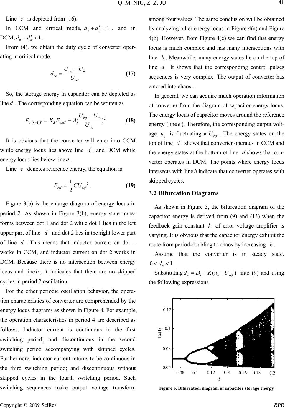 Q. M. NIU, Z. Z. JU Copyright © 2009 SciRes EPE 41 Line is depicted from (16). c In CCM and critical mode,, and in DCM,. 1 nn dd 1 nn dd From (4), we obtain the duty cycle of converter oper- ating in critical mode. ref in nc ref UU dU (17) So, the storage energy in capacitor can be depicted as line . The corresponding equation can be written as d 2 ,( 1),( ref in cnTS cnT ref UU EKEA U ) . (18) It is obvious that the converter will enter into CCM while energy locus lies above line , and DCM while energy locus lies below lined. d Line denotes reference energy, the equation is e 2 1 2 ref ref ECU. (19) Figure 3(b) is the enlarge diagram of energy locus in period 2. As shown in Figure 3(b), energy state trans- forms between dot 1 and dot 2 while dot 1 lies in the left upper part of line and dot 2 lies in the right lower part of line . This means that inductor current on dot 1 works in CCM, and inductor current on dot 2 works in DCM. Because there is no intersection between energy locus and line, it indicates that there are no skipped cycles in period 2 oscillation. d d b For the other periodic oscillation behavior, the opera- tion characteristics of converter are comprehended by the energy locus diagrams as shown in Figure 4. For example, the operation characteristics in period 4 are described as follows. Inductor current is continuous in the first switching period; and discontinuous in the second switching period accompanying with skipped cycles. Furthermore, inductor current returns to be continuous in the third switching period; and discontinuous without skipped cycles in the fourth switching period. Such among four values. The same conclusion will be obtained by analyzing other energy locus in Figure 4(a) and Figure 4(b). However, from Figure 4(c) we can find that energy locus is much complex and has many intersections with line b. Meanwhile, many energy states lie on the top of line . It shows that the corresponding control pulses sequences is very complex. The output of converter has entered into chaos. . In general, we can switching sequences make output voltage transform acquire much operation information of s ram of the ca ste. d converter from the diagram of capacitor energy locus. The energy locus of capacitor moves around the reference energy (linee). Therefore, the corresponding output volt- age 0 u is fluctuating atref U. The energy states on the top of line d shows thatverter operates in CCM and the energy states at the bottom of line dshows that con- verter operates in DCM. The points where energy locus intersects with linebindicate that converter operates with skipped cycles. 3.2 Bifurcation Diagram con As shown in Figure 5, the bifurcation diag pacitor energy is derived from (9) and (13) when the feedback gain constant k of error voltage amplifier is varying. It is obvious thathe capacitor energy exhibit the route from period-doubling to chaos by increasing k. Assume that the converter is in steady ta t 01 n d . () ns nref dDKuU Substituting into (9) and using the following expressions Figure 5. Bifurcation diagram of capacitor storage energy 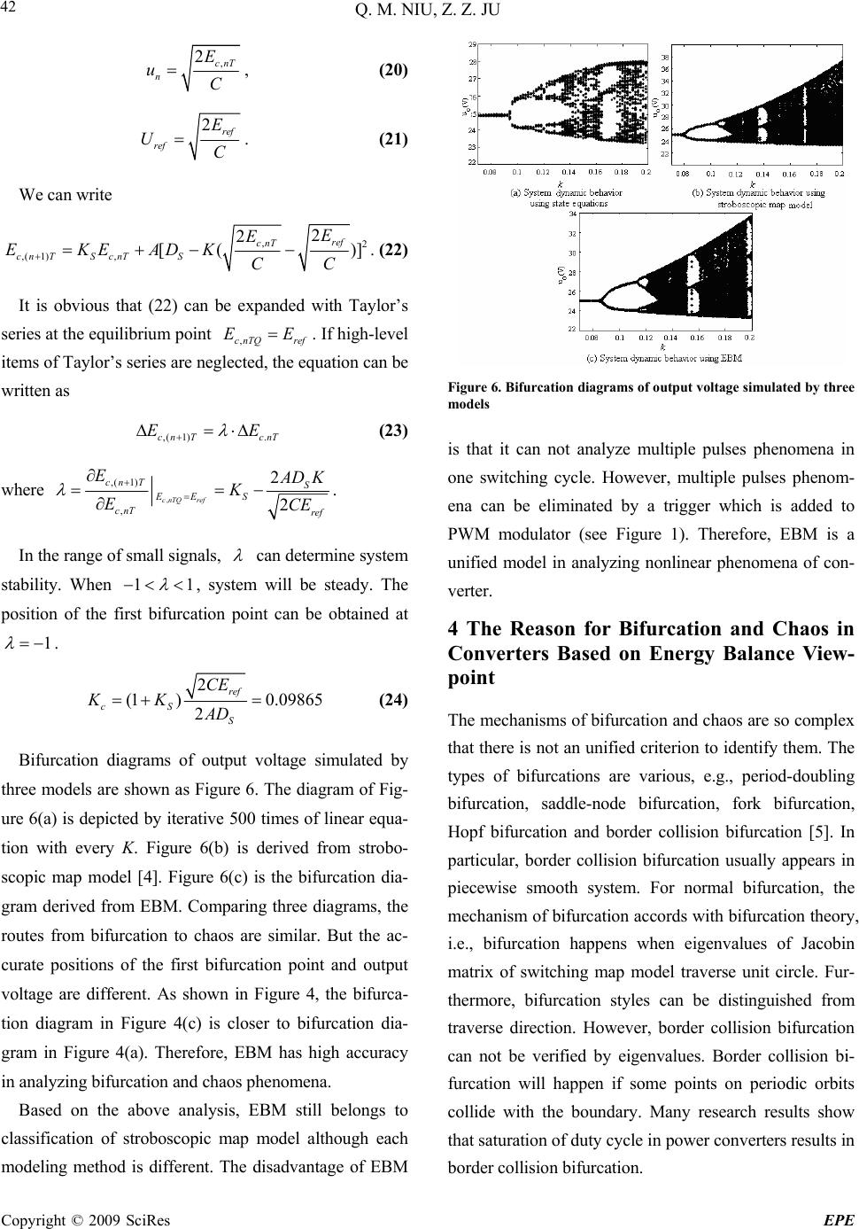 Q. M. NIU, Z. Z. JU Copyright © 2009 SciRes EPE 42 , 2EcnT n uC , (20) 2ref ref E UC . (21) We can write ,2 ,( 1), 2 2 [( ref cnT cnTScnTS E E EKEADK CC . )] It is obvious that (22) can be expanded with Taylor’s se (22) ries at the equilibrium point EE. If high-level items of Taylor’s series are neglected, the equation can be written as ,cnTQ ref ,( 1).cn T cnT EE (23) where , ,( 1) , 2 2 cnTQ ref cn TS EES cnT ref E A DK K ECE . In the range of small signals, can determine system stability. When 11 , system will be steady. The position of the fiion point can be obtained at 1 rst bifurcat . 2 (1 )0.09865 2 ref cS S CE KK AD (24) Bifurcation diagrams of output voltage simulated by odels are shown as Figure 6. The diagram of Fig- ure 6(a) is depicted by iterative 500 times of linear equa- tion with every K. Figure 6(b) is derived from strobo- scopic map model [4]. Figure 6(c) is the bifurcation dia- gram derived from EBM. Comparing three diagrams, the routes from bifurcation to chaos are similar. But the ac- curate positions of the first bifurcation point and output voltage are different. As shown in Figure 4, the bifurca- tion diagram in Figure 4(c) is closer to bifurcation dia- gram in Figure 4(a). Therefore, EBM has high accuracy in analyzing bifurcation and chaos phenomena. Based on the above analysis, EBM still b Figure 6. Bifurcation diagrams of output voltage simulated by three models is that it can not analyze multiple pulses phenomena na can be eliminated by a trigger which is added to bifurcations are various, e.g., period-doubling border collision bifurcation. in one switching cycle. However, multiple pulses phenom- e PWM modulator (see Figure 1). Therefore, EBM is a unified model in analyzing nonlinear phenomena of con- verter. 4 The Reason for Bifurcation and Chaos in Converters Based on Energy Balance View- point The mechanisms of bifurcation and chaos are so complex that there is not an unified criterion to identify them. The types of three m elongs to classification of stroboscopic map model although each modeling method is different. The disadvantage of EBM bifurcation, saddle-node bifurcation, fork bifurcation, Hopf bifurcation and border collision bifurcation [5]. In particular, border collision bifurcation usually appears in piecewise smooth system. For normal bifurcation, the mechanism of bifurcation accords with bifurcation theory, i.e., bifurcation happens when eigenvalues of Jacobin matrix of switching map model traverse unit circle. Fur- thermore, bifurcation styles can be distinguished from traverse direction. However, border collision bifurcation can not be verified by eigenvalues. Border collision bi- furcation will happen if some points on periodic orbits collide with the boundary. Many research results show that saturation of duty cycle in power converters results in 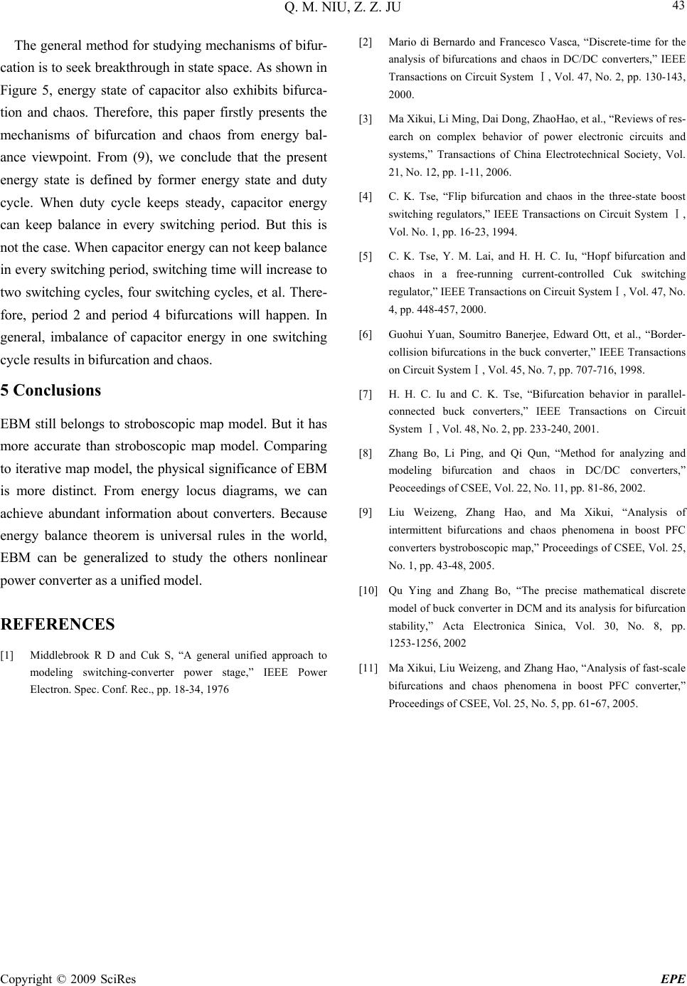 Q. M. NIU, Z. Z. JU Copyright © 2009 SciRes EPE 43 is paper firstly presents the m model. Comp , the physical significance of EBM rom energy locus diagrams, we can r stage,” IEEE Power Electron. Spec. Conf. Rec., pp. 18-34, 1976 pp. 130-143, s,” Transactions of China Electrotechnical Society, Vol. on Circuit System,Ⅰ Vol. 47, No. ol. 45, No. 7, pp. 707-716, 1998. 6, 2002. ol. 25, onica Sinica, Vol. 30, No. 8, pp. EE, Vol. 25, No. 5, pp. 61-67, 2005. The general method for studying mechanisms of bifur- cation is to seek breakthrough in state space. As shown in Figure 5, energy state of capacitor also exhibits bifurca- tion and chaos. Therefore, th echanisms of bifurcation and chaos from energy bal- ance viewpoint. From (9), we conclude that the present energy state is defined by former energy state and duty cycle. When duty cycle keeps steady, capacitor energy can keep balance in every switching period. But this is not the case. When capacitor energy can not keep balance in every switching period, switching time will increase to two switching cycles, four switching cycles, et al. There- fore, period 2 and period 4 bifurcations will happen. In general, imbalance of capacitor energy in one switching cycle results in bifurcation and chaos. 5 Conclusions EBM still belongs to stroboscopic map model. But it has more accurate than stroboscopic map aring [8] Zhang Bo, Li Ping, and Qi Qun, “Method for analyzing and modeling bifurcation and chaos in DC/DC converters,” Peoceedings of CSEE, Vol. 22, No. 11, pp. 81-8 to iterative map model is more distinct. F achieve abundant information about converters. Because energy balance theorem is universal rules in the world, EBM can be generalized to study the others nonlinear power converter as a unified model. REFERENCES [1] Middlebrook R D and Cuk S, “A general unified approach to modeling switching-converter powe [2] Mario di Bernardo and Francesco Vasca, “Discrete-time for the analysis of bifurcations and chaos in DC/DC converters,” IEEE Transactions on Circuit System Ⅰ, Vol. 47, No. 2, 2000. [3] Ma Xikui, Li Ming, Dai Dong, ZhaoHao, et al., “Reviews of res- earch on complex behavior of power electronic circuits and system 21, No. 12, pp. 1-11, 2006. [4] C. K. Tse, “Flip bifurcation and chaos in the three-state boost switching regulators,” IEEE Transactions on Circuit System Ⅰ, Vol. No. 1, pp. 16-23, 1994. [5] C. K. Tse, Y. M. Lai, and H. H. C. Iu, “Hopf bifurcation and chaos in a free-running current-controlled Cuk switching regulator,” IEEE Transactions 4, pp. 448-457, 2000. [6] Guohui Yuan, Soumitro Banerjee, Edward Ott, et al., “Border- collision bifurcations in the buck converter,” IEEE Transactions on Circuit System,Ⅰ V [7] H. H. C. Iu and C. K. Tse, “Bifurcation behavior in parallel- connected buck converters,” IEEE Transactions on Circuit System ,Ⅰ Vol. 48, No. 2, pp. 233-240, 2001. [9] Liu Weizeng, Zhang Hao, and Ma Xikui, “Analysis of intermittent bifurcations and chaos phenomena in boost PFC converters bystroboscopic map,” Proceedings of CSEE, V No. 1, pp. 43-48, 2005. [10] Qu Ying and Zhang Bo, “The precise mathematical discrete model of buck converter in DCM and its analysis for bifurcation stability,” Acta Electr 1253-1256, 2002 [11] Ma Xikui, Liu Weizeng, and Zhang Hao, “Analysis of fast-scale bifurcations and chaos phenomena in boost PFC converter,” Proceedings of CS |