Circuits and Systems
Vol.07 No.09(2016), Article ID:69297,14 pages
10.4236/cs.2016.79239
Neuro-Fuzzy Based Interline Power Flow Controller for Real Time Power Flow Control in Multiline Power System
A. Saraswathi1*, S. Sutha2
1Department of Electrical and Electronics Engineering, University College of Engineering Villupuram, Anna University, Chennai, India
2Department of Electrical and Electronics Engineering, University College of Engineering Dindigul, Anna University, Chennai, India

Copyright © 2016 by authors and Scientific Research Publishing Inc.
This work is licensed under the Creative Commons Attribution International License (CC BY).
http://creativecommons.org/licenses/by/4.0/


Received 24 March 2016; accepted 15 April 2016; published 29 July 2016
ABSTRACT
This article investigates the power quality enhancement in power system using one of the most famous series converter based FACTS controller like IPFC (Interline Power Flow Controller) in Power Injection Model (PIM). The parameters of PIM are derived with help of the Newton-Rap- hson power flow algorithm. In general, a sample test power system without FACTs devices has generated more reactive power, decreased real power, more harmonics, small power factor and poor dynamic performance under line and load variations. In order to improve the real power, compensating the reactive power, proficient power factor and excellent load voltage regulation in the sample test power system, an IPFC is designed. The D-Q technique is utilized here to derive the reference current of the converter and its D.C link capacitor voltage is regulated. Also, the reference voltage of the inverter is arrived by park transformation technique and its load voltage is controlled. Here, a sample 230 KV test power system is taken for study. Further as the conventional PI controllers are designed at one nominal operating point they are not competent to respond satisfactorily in dynamic operating conditions. This can be circumvented by a Fuzzy and Neural network based IPFC and its detailed Simulink model is developed using MATLAB and the overall performance analysis is carried out under different operating state of affairs.
Keywords:
FACTS Controller, Fuzzy Logic Controller, Interline Power Flow Controller, Reactive Power Compensation (RPC), Voltage Stability

1. Introduction
In current scenario, the transmission and distribution networks are densely populated due to the surplus demand of global energy consumption. Constructing a new transmission network becomes a challenging one, because of the environmental impacts related with law and legislative cries. Also, the cost effective technical challenges are presented in deregulation of the power network. In general, the distance between generating units and load centers are far away. For that reasons losses are huge. So as to minimize the power losses and also to ensure high- quality power supply up to the end user, concern must be taken. To rectify such troubles, embedding FACTS controllers in power system is play a vital role and may offer proficient control with safe working conditions. Even though FACTS technology (based on thyristor operation) is invented in 1986 by N.G. Hingorani in Electric Power Research Institute (EPRI) USA, and tremendous improvement in high power electronics like IGBT and GTO is achieved, the converter based FACTS technology come to picture after one decade. Inter line power flow controller (IPFC) was proposed by Gyugi in 1998 [1] and its specialty is not only its multi functionality but also its controllability of multi transmission lines in a substation. Controlling the converter operation and hence real power flow in specific corridor and reactive power compensation without huge AC capacitor bank and bulk reactor is possible.
The controllable converter output voltage is injected into the transmission lines using properly designed series transformer. This is most fortune to emulate capacitive/inductive effect in the transmission lines. Hence only controlling the converter parameters, power flow control in the system is obtained. In the case of deregulation energy market, where transmission lines are utilized up to its thermal limits, this innovative idea is highly appreciable. IPFC may consist of m number of inverters connected in different transmission lines using separate m number of series transformers and share a common DC source. In other words it consists of more than one SSSC with common DC link [2] . In a typical transmission system with the exchange of reactive power between the series converter and the network, control the flow of active power through the transmission line is achieved [3] . In general the stability limit is defined as the maximum power which can flow through a point in the system without causing loss of stability. After a small slow disturbance a system may regain and maintain its operating condition is known as steady state stability and the same for large and sudden disturbance it is known as transient state stability. The latter one is all ways greater than the previous one [4] . Another important stability is dynamic stability and during its study a large disturbance like short circuit/loss of generation/loss of load is analyses for long period of time like 4 - 10 seconds.
Especially, when large rating generators are connected to a long transmission lines, due to its large steady state synchronous reactance, poor load-voltage characteristics may occur and leads to significant drop in synchronizing torque which promote to transient stability related problems. Moreover there is a high degree of uncertainty present in the power system behavior, after and before a fault occurrence [5] . Hongesombut et al. [6] applied phase plane fuzzy logic to control the frequency robustly and to improve the power system stability due to the uncertainty of power produced from the installed wind turbine in the system. In [7] a hybrid algorithm is formed by the contribution of genetic algorithm (GA) and gravitational search algorithm (GSA) for optimal setting of IPFC. Amir Ghorbani et al. first time investigate the effect of the GIPFC on the measured impedance by loss of excitation (LOE) relay of synchronous generation [8] . A new concept of SIPFC is in adopted version of IPFC which eliminates the common dc link is presented in [9] . In [10] security constrained unit commitment (SCUC) problem is solved using ABC algorithm incorporating IPFC. The injection model for congestion management and total active power failure minimization in electric power system has been developed [11] . Mustafa et al using intelligent techniques for the selection of parameters of IPFC as an optimization problem and the effectiveness of the IPFC in diminishing transmission power losses is demonstrated [12] .
In this paper ATC enhancement of test power system with IPFC is studied with MATLAB software. The reviewed power injection model (PIM) of IPFC is considered for steady state analysis. The paper is organized, in Section 1; the introduction is given in terms of the necessity of FACTS controllers and need of IPFC. Section 2 summarizes the basic concepts, operating principle followed by problem formulation in Section 3. The state space modeling of IPFC is given in Section 4. A standard five bus system is considered as test system for performance analysis. The need of the Fuzzy based controller, fuzzy inference system and its rules are given in Section 5. The neural network based controller for slave converter of IPFC is described in Section 6. Eventually in Section 7 the simulation results with discussion and important conclusions drawn from the simulation studies are given.
2. Working Principle of IPFC
An elementary IPFC scheme consists of two back-to-back DC-to-AC converters; each compensating a transmission line by series voltage injection is shown in Figure 1. The reactive power control can be totally independent in each converter whereas the real power flowing into or out of each converter has to be coordinated in such a way that the DC link voltage is kept constant also the overall surplus power from the under-utilized lines can be used by other over loaded lines for real power compensation. The DC to AC converter is basically voltage source converter and can inject a controllable voltage into the transmission line irrespective of the transmission line current. Hence the effective impedance of the transmission line is changed as either inductive or capacitive in nature that is reactive series compensation is obtained [13] .
In general the transmission lines are inductive in nature as its resistance is very small compared to its inductive reactance. Hence  and
and . The real power transfer from the sending end is given by
 (1)
(1)
where, Vs―is the magnitude of sending end voltage,
Vr―is the magnitude of receiving end voltage,
δ―is the phase difference between sending and receiving end voltages.
When series connected converter inject voltage in quadrature with the transmission line current it can emulate either inductive or capacitive reactance in the line. Consider Equation (1) and assume the series converter inject a controllable voltage in the transmission line in such a way to emulate capacitance effect. Hence the net effective reactance of the line is reduced and power transmission capacity is increased.
 (2)
(2)
It is clear that for the same values of V and δ the transmittable real power Ps3 is higher than the Ps2. The increase in transfer power is given by
 (3)
(3)

Figure 1. Schematic block diagram of IPFC.
The factor K is known as degree of compensation percentage (%).
3. Problem Formation
The basic building block of IPFC is series connected voltage source converter (VSC). In the case of the series connected VSC, the current flowing through the transmission line has an impact on the dc circuit by means of average switching functions. Since under the steady sate condition, the converter at the AC terminals can exchange only reactive power with the system, when neglecting losses the series injected voltage always has to be perpendicular to the current flowing through the transmission line. But at wide transmission angles or large line current even a small displacement from the balance position can cause major displacement from the balance position and can cause major changes in the voltage across the dc condenser. This fact has to be taken into consideration when deriving a control algorithm and selecting the size of condenser. The equivalent circuit model of IPFC in simplified form is shown in Figure 2. In case of shunt connected converter in STATCOM there is almost linear dependence between the output voltage amplitude of the shunt VSC and the reactive current component. Also the linearity is maintained between the phase angle and active current component flowing between the shunt compensator and the network [14] . But in the case of series connected voltage source converter this relationship is not clearly evident. For the given transmission angle it is evident from the presented steady state characteristics that the active component of the series current primarily and almost depends on the average switching function in the direction.
Another important constrain is the active power invariance of IPFC. That is the sum of real power exchange between IPFC and System is zero with loss less converter valves and no independent energy storage. In general by controlling the injection voltage magnitude and phase angle the power flow control in the transmission line is achieved. The injection of a controlled voltage from converter1 results in exchange of active and reactive power between Convertyer1 and line1. The active power component Psc1 imposes a demand to the DC terminals. But converter2 is forced by the active power invariance constraint. Hence unlike converter1 the operation of converter2 has its freedom degrees reduced; its series voltage V2pq can compensate only partially to its own line and this imposes a restriction mainly on its power flow. Also the converter2 has another task of regenerating the DC link voltage. So the Psc2 component of converter2 is predefined. Under this condition the primary system will have priority over the secondary system in achieving its set point requirements. Hence a decoupling algorithm is used to control the IPFC operation [15] . In this work convert1 is meant for both real and reactive power flow control. For this a fuzzy based controller is designed because it can handle nonlinearity more robust than conventional nonlinear controllers. Converter2 is meant for reactive power compensation and to maintain DC link voltage constant. A Neural network based controller is designed to meet out the converter2 controlling operation. For this a multi-layer feed-forward neural network based controller with back propagation learning process is used [16] .
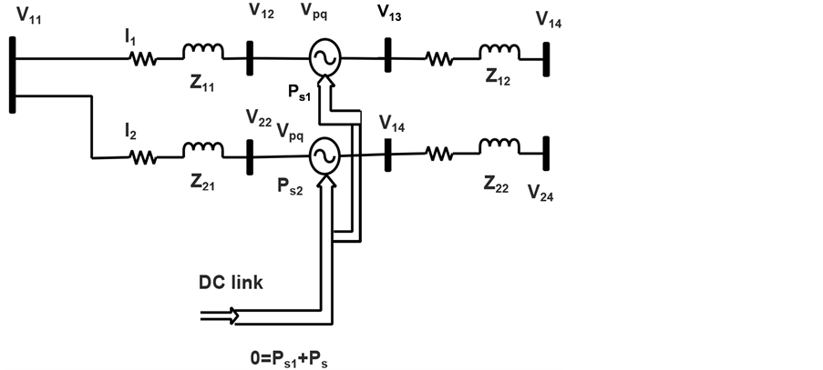
Figure 2. Equivalent circuit model of IPFC.
4. State Space Modeling of IPFC
The outputs of two converters are coupled to the transmission lines by using two different series transformer. The injected voltage vector is controllable irrespective of the transmission line current. Hence it can stimulate effective impedance of the transmission lines and power flow control is obtained even power from underutilized lines to heavily loaded lines. The test system considers here is a single machine infinite bus system. In practical the power system is highly interconnected with large number of synchronous generators and huge number of loads. For easy analyzing purpose the power system may be grouped as power exporting area and power importing area. The exporting area simply represented by a single equivalent generator. Similarly the power importing area is represented by an equivalent synchronous motor. Hence a multi machine power system model reduced into two machine problem. It can further reduce to single machine connected to an infinite bus-a constant voltage constant frequency system [17] . The dynamic modeling of IPFC is considered for analysis [18] .
 (4)
(4)
 (5)
(5)
 (6)
(6)
The dynamic model of the power system may be expressed by these nonlinear equations.
 (7)
(7)
 (8)
(8)
 (9)
(9)
 (10)
(10)
Then the state model of the power system with IPFC is
 (11)
(11)
where X is the state vectors, U is the control vectors, A is the system matrix and B is the control matrix respectively [7] .
 (12)
(12)
 (13)
(13)
 (14)
(14)
 (15)
(15)
Assume that initially the power system is operating under synchronous equilibrium that is the rotor angles of the different machines are fixed one with respect to the rotating synchronous reference frame. Also the system may be in frequency equilibrium state which means that the operating frequency of the power system is constant. An infinite bus is one whose voltage and frequency are unaffected by a disturbance in the machine under consideration.
In general synchronous reference frame SRF-PLL uses Park’s transformation as the phase differentiator and hence not able to track instantaneous evolution of the voltage vector when the PLL bandwidth is low. In case of unbalanced condition as components in d and q axis components make it difficult to track phase angle. In this paper a DSRF control which is works well even for unbalanced condition is presented. It is a combination of two SRF-PLLs which can detect the positive and negative sequence components of voltage vector separately [19] . The D-Q control for Power Flow control mode of IPFC is shown in Figure 3. At the receiving end the real and reactive power is sensed and the d and q component of the current vector is calculated. The actual and reference current vectors are compared and the corresponding error signals are processed by the PI controllers. The feed forward cross coupling reduced errors due to unbalanced components in the current vectors. Next the required direct and quadrature component of the series voltage is determined and injected in to the transmission line. The overall simulation circuit of IPFC with test power system is developed. The specifications of the test system are given in Table 1. The controller is support the system under steady state condition by tracking the set reference values as shown in Figure 8 and Figure 9. But during transient condition like sudden load variation the results proven that the needs of efficient controller, as PI parameters are tuned to a particular operating condition.

Figure 3. D-Q control diagram of IPFC.

Table 1. Specification of the test system.
5. Fuzzy Control Scheme for Master Converter of IPFC
Fuzzy logic is introduced by LotfiZadeh in 1965 to process imprecise data and the basic concept is attempted to mimic human control logic. The mathematical modeling of FACTS controller is complex but in case of fuzzy logic controller there is no need of accurate mathematical model of the system going to be controlled and can work with imprecise inputs. Practically it doesn’t need fast processors and it needs less data storage in the form of membership functions and rules than conventional look up table for nonlinear controllers [20] . Power converters are inherently nonlinear. The causes of nonlinearity in the power converters include a variable structure within a single switching period, saturating inductances, voltage clamping etc. Even the FACTS controllers are highly accurate and fast dynamic in nature, they interact with other static controllers always accompanied with non-linearity and uncertainties. For the sake of power quality it is forced to defeat the stability. The Fuzzy Logic Controller (FLC) has many advantages than the conventional PI controllers. It can handle nonlinearity and more robust than conventional nonlinear controllers. It is a controller based on the concepts of fuzzy sets, linguistic variables and approximate reasoning to evaluate rules. The set of rules are represents the control decision mechanisms required to adjust the effect of certain cases. The internal structure of FLC is shown in Figure 4. FLC are range to range and range to point controllers and the input of FLC is membership function and the output also depends on membership function.
In conventional controller we have control gain or control loss, which are combination of numerical values. In FLC instead of fixed gain or loss, the updated variables are used in terms of rules and they are linguistic in nature [11] . Such a typical rule can be written as follows:
IF E is Ai and CE is Bi then output is Ci (16)
where, Ai, Bi and Ci are the labels of linguistic variables of Error (E), Change of Error (CE) and output respectively. E, CE and output represent degree of membership. The internal structure FIS Fuzzy editor with four inputs and two outputs are shown in Figure 5. A basic architecture of FLC contains fuzzification, inference mechanism, fuzzy rule base, and defuzzification. Fuzzification converts binary data into fuzzy data it has two processes that is derive the membership function for input and output variables. Defuzzification process is to derive the desired crisp output value by combining the membership functions with fuzzy rules. It converts fuzzy o/p values to control signals. It derived by two category, one is off line defuzzification, here all input and output membership functions are based on actual experience, i.e., specified application. Online method is real time controllability has higher control accuracy. Fuzzy set allows objects or members to represent a smooth boundary whereas classical represent sharp boundary and the membership function take the value in the interval 0 and 1. It is derived by different methods like triangular waveform, trapezoidal, sigmoidal, guassian, bell etc. In this study the min inference rule and centroid defuzzzification technique have been used [13] .
6. ANN Control Scheme for Slave Converter of IPFC
Neural Network (NN) has been widely used to solve complex problems of pattern recognition and they can recognize patterns very fast after they have already been trained. The training process requires a training algorithm, which uses the training data set to adjust the networks weights and bias so as to minimize an error function, such as the mean squared error function (MSE), and try to classify all patterns in the training data set [21] . The internal structure of ANN control is depicted in Figure 6. It is very important to choose a proper algorithm for

Figure 4. Internal structure of fuzzy logic controller.

Figure 5. Fuzzy editor with 4 inputs and 2 outputs.

Figure 6. The structure of ANN control.
training a neural network. In this paper Back Propagation (BP) training algorithm is used.
The slave converter in IPFC is used to maintain the DC link voltage constant and provide reactive power compensation for line where it is connected. The NN based controller is used to generate control signal for converter2 and hence required reactive power compensation is obtained. The stopping condition of training algorithm is either more number of iteration or up to no variation in the weights.
7. Simulation Results and Discussion
In this section, the circuit model of IPFC with four bus test system is presented. The open loop IPFC circuit model has been developed. Two three phase converters designed and connected back to back each other and their controllers were built in MATLAB/Simulink. The AC side controlled voltage is fed to the transmission lines by using two different series transformer. It is clear that by injecting proper series voltage the impedance of the transmission line is changed either inductive or capacitive effect as shown in Figure 11. The DC link voltage, AC side voltage and current waveforms are shown in Figure 7. The real and reactive power at receiving end is measured. Also at steady sate, the IPFC enhance the real power by reactive power compensation as shown in Figure 8. The IPFC with PI controllers are working well in the limited variation but at higher degree of variation it is failed to hold the stability of the system. To study the performance of the test system with IPFC a voltage fluctuation both voltage swell and sag are externally created and the corresponding power flow at four bus are measured. Up to 5% of voltage variation the series voltage compensation is in effective and maintained constant voltage. But at the same time the THD value at load 2 is worse than the uncompensated line at load1, which can be improved by placing a LC filter circuit. The total harmonic distortion is 12.5%, which is greater than IEEE standard value hence a filter is designed to reduce the harmonics and therefore the heating in the injecting transformer is reduced. Further improvement in THD is obtained by introducing a LC filter at the load side as in Figure 9. The impedance response of IPFC both in capacitive and inductive mode is shown in Figure 10.
Also, the transmission line where master converter is connected has upper hand than the other one in holding settling point. Figure 11 and Figure 12 show this effect clearly with load variation. This is due to the presence of common interlinking capacitor. The fault clearance time is improved due to the presence of IPFC as depicted in Figure 13. The peak overshoot of the real and reactive power is comparatively reduced as shown in Figure 14. The current through the capacitor and voltage across it is shown in Figure 15. The overall power flow during fluation in the supply side with the presence of IPFC is depicted in bar chart as Figure 16. At 20% change of supply voltage in the positive direction is the worst case compared to the reverse direction that is −20% change of supply voltage.

Figure 7. AC, DC voltage and current of VSC.

Figure 8. Real and reactive powers.


Figure 9. THD of VSC.


Figure 10. Frequency response of IPFC.

Figure 11. P & Q under load variation.
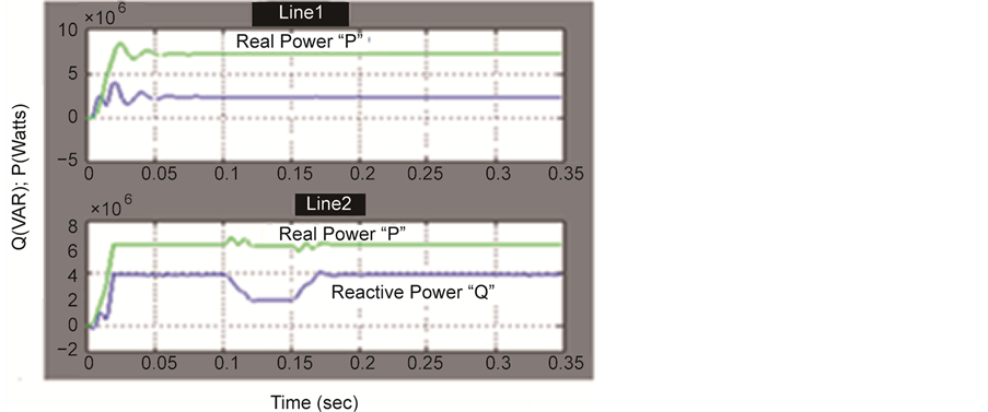
Figure 12. P & Q under load variation.

Figure 13. Line voltage during Fault condition.

Figure 14. Q-response during Fault condition.
8. Conclusion
In this paper, a detailed circuit model of two converter IPFC for real power flow control and reactive power compensation with designed controller (like: FLC, ANN, and reference calculation D-Q method) has been successfully demonstrated using MATAB/Simulink software platform. A FLC based converter operation is meant for
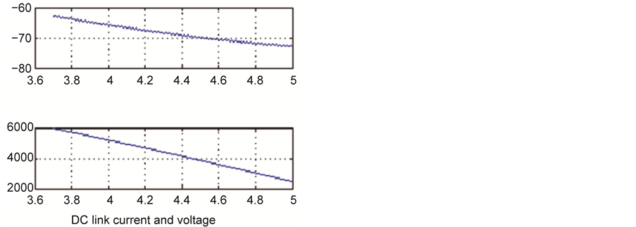
Figure 15. DC link voltage and current.
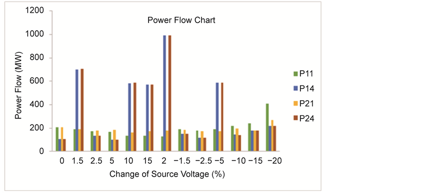
Figure 16. Power Flow during fault.
independent real and reactive power control. The ANN based converter limited operation is meant for reactive power compensation and to maintain constant DC link voltage. The performance of entire system with IPFC is studied and the simulation results show that using FLC and ANN enhanced the system performance in steady state region and limited in transient state region. In future, the training algorithm is to be modified for ANN and number of rules increased in FLC to meet out the set-back in transient state performance.
Cite this paper
A. Saraswathi,S. Sutha, (2016) Neuro-Fuzzy Based Interline Power Flow Controller for Real Time Power Flow Control in Multiline Power System. Circuits and Systems,07,2807-2820. doi: 10.4236/cs.2016.79239
References
- 1. Gyugyi, L., Sen, K.K. and Schauder, C.D. (1999) The Inter Line Power Flow Controller Concept: A New Approach to Power Flow Management in Transmission Systems. IEEE Transactions on Power Delivery, 14, 1115-1123.
http://dx.doi.org/10.1109/61.772382 - 2. Zhang, J. and Yokoyama, A. (2007) Application of Inter Line Power Flow Controller to ATC Enhancement by Optimal Power Flow Control. IEEE Lausanne Power Tech, Lausanne, 1-5 July 2007, 1226-1231.
- 3. Papic, I. (2000) Mathematical Analysis of FACTS Devices Based on a Voltage Source Converter Part I: Steady State Operational Characteristics. EPSR, 56, 139-148.
- 4. Kundur, P., Paserba, J., et al. (2004) Definition and Classification of Power System Stability. IEEE Transaction in Power Systems, 19, 1387-1401.
- 5. Kumar, A. and Yadav, R.S. (2011) Fault Polerance in Real Time Distributed System. International Journal on Computer Science and Engineering, 3, 933-939.
- 6. Hongesombut, K., Kerdphol, T. and Weerakamaeng, Y. (2013) Robust Inter Line Power Flow Controller Using Phase Plane Fuzzy Logic Control. 10th International Conference on Electrical Engineering/Electronics, Computer, Telecommunications and Information Technology (ECTI-CON), Krabi, 15-17 May 2013, 1-4.
- 7. Sai Ram, I. and Amarnath, J. (2013) Optimal Setting of IPFC for Voltage Stability Improvement Using (GA-GSA) Hybrid Algorithm. Nirma University International Conference on Engineering (NUiCONE), Ahmedabad, 28-30 November 2013, 1-6.
- 8. Ghorbani, A., Soleymani, S. and Mozafari, B. (2015) A PMU-Based LOE Protection of Synchronous Generator in the Presence of GIPFC. IEEE Transactions on Power Delivery, 31, 551-558.
- 9. Yuan, Z.H., DeHaan, S.W.H. and Ferreira, B. (2008) A New Concept of Exchanging Active Power without Common DC Link for Inter Line Power Flow Controller (S-IPFC). Power and Energy Society General Meeting—Conversion and Delivery of Electrical Energy in the 21st Century, IEEE, 1-7.
- 10. Sreejith, S., Simon, S.P. and Padhy, N.P. (2013) Estimation of Recovery Cost with the Incorporation of an IPFC in a SCUC Problem. IEEE Power & Energy Society General Meeting, Vancouver, 21-25 July 2013, 1-5.
- 11. Naresh, B. and Kummar, J.A. (2013) Performance Evaluation of FACTS Controller for Power Flow Management in Transmission System Using IPFC Applied to Induction Derive. International Journal of Electrical and Electronics Engineering, 4, 2231-5184.
- 12. Al Khabbaz, M.M. (2014) Transmission Power Loss Reduction Using Intelligent Techniques-Regulated IPFC. IEEE Conference on Energy Conversion (CENCON), Johor Bahru, 13-14 October 2014, 423-428.
- 13. Saraswathi, A. and Sutha, S. (2015) Fuzzy Logic Controller Based Interline Power Flow Controller and Its Performance Analysis. Applied Mathematical Sciences, 9, 3651-3658.
- 14. Papic, I. (2000) Analysis of FACTS Devices Based on a Voltage Source Converter Part II: Steady State Operational Characteristics. EPSR, 56, 149-157.
- 15. Saraswathi, A. and Sutha, S. (2014) Detailed Simulink Modeling and Analysis of Interline Power Flow Controller for Multiline System. ICIRET.
- 16. Rutkowski, L. (2008) Computational Intelligence Methods and Techniques. Springer-Verlaq.
- 17. Padiyar, K.R. (2007) FACTS Controllers in Power Transmission and Distribution. New Age International Pvt. Limited, New Delhi.
- 18. Spandana, M. and Rao, T. (2014) Dual Damping Controller Using Interline Power Flow Controller. IJATCSE, 3, 363- 368.
- 19. Salem, S. and Sood, V.K. (2007) Simulation and Controller Design of an Interline Power Flow Controller in EMTP RV. International Conference on Power Systems Transients (IPST’07), Lyon, 4-7 June 2007, 1-8.
- 20. Ross, T.J. (2010) Fuzzy Logic with Engineering Applications. 2nd Edition, Wiley India Pvt. Limited, New Delhi.
PMid:20386946 PMCid:PMC2914240 - 21. Shahgholilan, G., Mahadavian, M., et al. (2014) Design of a New IPFC-Based Damping Neurocontrol for Enhancing Stability of a Power System Using Particle Swarm Optimization. IJSEE, 3, 73-78.
NOTES

*Corresponding author.