Paper Menu >>
Journal Menu >>
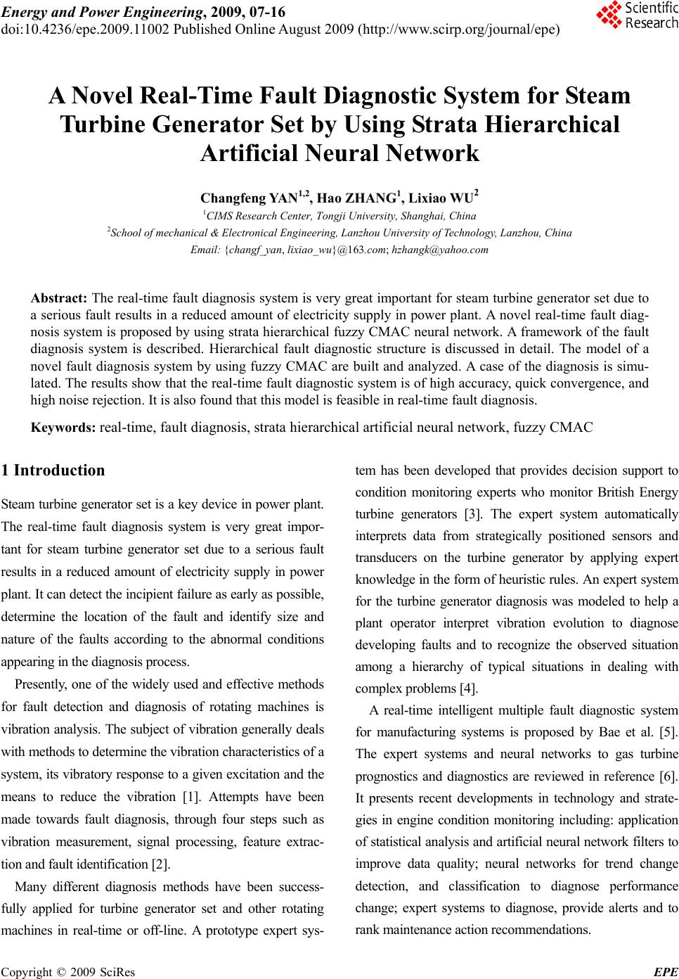 Energy and Power Engineering, 2009, 07-16 doi:10.4236/epe.2009.11002 Published Online August 2009 (http://www.scirp.org/journal/epe) Copyright © 2009 SciRes EPE A Novel Real-Time Fault Diagnostic System for Steam Turbine Generator Set by Using Strata Hierarchical Artificial Neural Network Changfeng YAN1,2, Hao ZHANG1, Lixiao WU2 1CIMS Research Center, Tongji University, Shanghai, China 2School of mechanical & Electronical Engineering, Lanzhou University of Technology, Lanzhou, China Email: {changf_yan, lixiao_wu}@163.com; hzhangk@yahoo.com Abstract: The real-time fault diagnosis system is very great important for steam turbine generator set due to a serious fault results in a reduced amount of electricity supply in power plant. A novel real-time fault diag- nosis system is proposed by using strata hierarchical fuzzy CMAC neural network. A framework of the fault diagnosis system is described. Hierarchical fault diagnostic structure is discussed in detail. The model of a novel fault diagnosis system by using fuzzy CMAC are built and analyzed. A case of the diagnosis is simu- lated. The results show that the real-time fault diagnostic system is of high accuracy, quick convergence, and high noise rejection. It is also found that this model is feasible in real-time fault diagnosis. Keywords: real-time, fault diagnosis, strata hierarchical artificial neural network, fuzzy CMAC 1 Introduction Steam turbine generator set is a key device in power plant. The real-time fault diagnosis system is very great impor- tant for steam turbine generator set due to a serious fault results in a reduced amount of electricity supply in power plant. It can detect the incipient failure as early as possible, determine the location of the fault and identify size and nature of the faults according to the abnormal conditions appearing in the diagnosis process. Presently, one of the widely used and effective methods for fault detection and diagnosis of rotating machines is vibration analysis. The subject of vibration generally deals with methods to determine the vibration characteristics of a system, its vibratory response to a given excitation and the means to reduce the vibration [1]. Attempts have been made towards fault diagnosis, through four steps such as vibration measurement, signal processing, feature extrac- tion and fault identification [2]. Many different diagnosis methods have been success- fully applied for turbine generator set and other rotating machines in real-time or off-line. A prototype expert sys- tem has been developed that provides decision support to condition monitoring experts who monitor British Energy turbine generators [3]. The expert system automatically interprets data from strategically positioned sensors and transducers on the turbine generator by applying expert knowledge in the form of heuristic rules. An expert system for the turbine generator diagnosis was modeled to help a plant operator interpret vibration evolution to diagnose developing faults and to recognize the observed situation among a hierarchy of typical situations in dealing with complex problems [4]. A real-time intelligent multiple fault diagnostic system for manufacturing systems is proposed by Bae et al. [5]. The expert systems and neural networks to gas turbine prognostics and diagnostics are reviewed in reference [6]. It presents recent developments in technology and strate- gies in engine condition monitoring including: application of statistical analysis and artificial neural network filters to improve data quality; neural networks for trend change detection, and classification to diagnose performance change; expert systems to diagnose, provide alerts and to rank maintenance action recommendations. 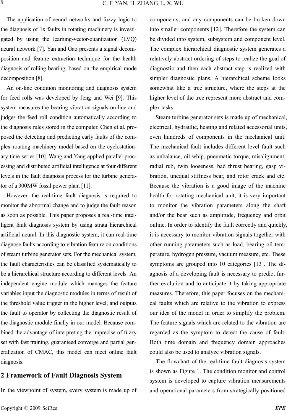 C. F. YAN, H. ZHANG, L. X. WU Copyright © 2009 SciRes EPE 8 The application of neural networks and fuzzy logic to the diagnosis of 1x faults in rotating machinery is investi- gated by using the learning-vector-quantization (LVQ) neural network [7]. Yan and Gao presents a signal decom- position and feature extraction technique for the health diagnosis of rolling bearing, based on the empirical mode decomposition [8]. An on-line condition monitoring and diagnosis system for feed rolls was developed by Jeng and Wei [9]. This system measures the bearing vibration signals on-line and judges the feed roll condition automatically according to the diagnosis rules stored in the computer. Chen et al. pro- posed the detecting and predicting early faults of the com- plex rotating machinery model based on the cyclostation- ary time series [10]. Wang and Yang applied parallel proc- essing and distributed artificial intelligence at four different levels in the fault diagnosis process for the turbine genera- tor of a 300MW fossil power plant [11]. However, the real-time fault diagnosis is required to monitor the abnormal change and to judge the fault reason as soon as possible. This paper proposes a real-time intel- ligent fault diagnosis system by using strata hierarchical artificial neural. In this diagnostic system, it can real-time diagnose faults according to vibration feature on conditions of steam turbine generator sets. For the mechanical system, the fault characteristics can be classified systematically to be a hierarchical structure according to different levels. An independent engine module which manages the feature variables input the diagnostic modules in terms of result of the threshold value trigger in the higher level, and outputs the fault to operator by collecting the diagnostic result of the diagnostic module finally in our model. Because com- bined the advantage of interpreting the imprecise of fuzzy set with fast training, guaranteed converge and partial gen- eralization of CMAC, this model can meet online fault diagnosis. 2 Framework of Fault Diagnosis System In the viewpoint of system, every system is made up of components, and any components can be broken down into smaller components [12]. Therefore the system can be divided into system, subsystem and component level. The complex hierarchical diagnostic system generates a relatively abstract ordering of steps to realize the goal of diagnostic and then each abstract step is realized with simpler diagnostic plans. A hierarchical scheme looks somewhat like a tree structure, where the steps at the higher level of the tree represent more abstract and com- plex tasks. Steam turbine generator sets is made up of mechanical, electrical, hydraulic, heating and related accessorial units, even hundreds of components in the mechanical unit. The mechanical fault includes different level fault such as unbalance, oil whip, pneumatic torque, misalignment, radial rub, twin looseness, bad thrust bearing, gasp vi- bration, unequal stiffness bear, and rotor crack and etc. Because the vibration is a good image of the machine health for rotating mechanical unit, it is very important to monitor the vibration parameters along the shaft and/or the bear such as amplitude, frequency and orbit online. In order to identify the fault correctly and quickly, it is necessary to monitor vibration signals together with other running parameters such as load, bearing oil tem- perature, hydrogen pressure, vacuum measure, etc. These symptoms are grouped into 10 categories [13]. The di- agnosis of a developing fault is necessary to predict fur- ther evolution and to anticipate it by taking appropriate measures. Therefore, this paper focuses on the mechani- cal faults which are relative to the vibration to express our idea of the model in order to simplify the problem. The feature signals which are related to the vibration are regarded as the symptom to detect the cause of fault. Both time domain and frequency domain approaches could also be used to analyze vibration signals. The flowchart of the real-time fault diagnosis system is shown as Figure 1. The condition monitor and control system is developed to capture vibration measurements and operational parameters from strategically positioned 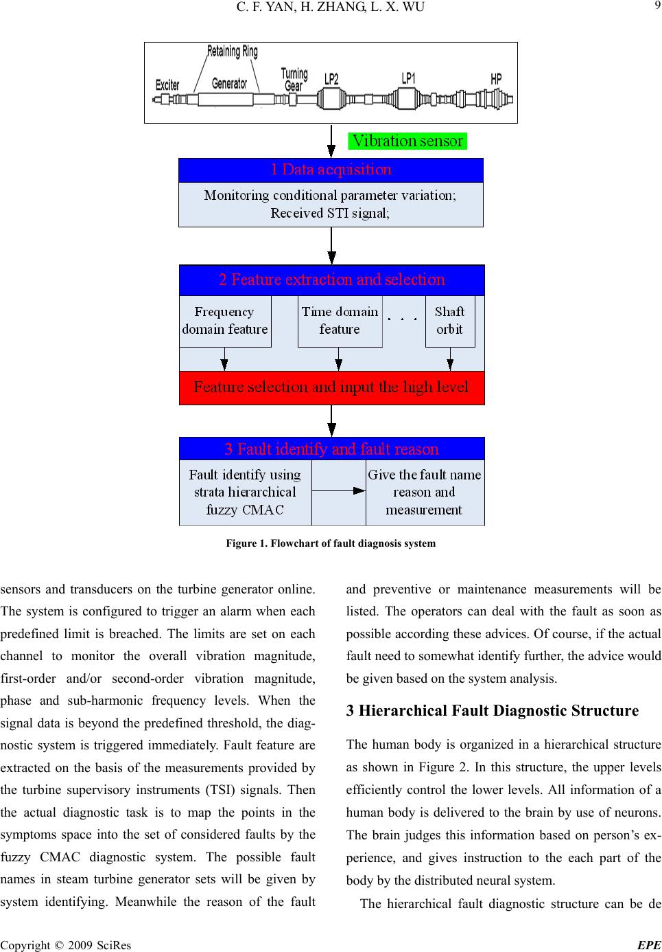 C. F. YAN, H. ZHANG, L. X. WU Copyright © 2009 SciRes EPE 9 Figure 1. Flowchart of fault diagnosis system sensors and transducers on the turbine generator online. The system is configured to trigger an alarm when each predefined limit is breached. The limits are set on each channel to monitor the overall vibration magnitude, first-order and/or second-order vibration magnitude, phase and sub-harmonic frequency levels. When the signal data is beyond the predefined threshold, the diag- nostic system is triggered immediately. Fault feature are extracted on the basis of the measurements provided by the turbine supervisory instruments (TSI) signals. Then the actual diagnostic task is to map the points in the symptoms space into the set of considered faults by the fuzzy CMAC diagnostic system. The possible fault names in steam turbine generator sets will be given by system identifying. Meanwhile the reason of the fault and preventive or maintenance measurements will be listed. The operators can deal with the fault as soon as possible according these advices. Of course, if the actual fault need to somewhat identify further, the advice would be given based on the system analysis. 3 Hierarchical Fault Diagnostic Structure The human body is organized in a hierarchical structure as shown in Figure 2. In this structure, the upper levels efficiently control the lower levels. All information of a human body is delivered to the brain by use of neurons. The brain judges this information based on person’s ex- perience, and gives instruction to the each part of the body by the distributed neural system. The hierarchical fault diagnostic structure can be de  C. F. YAN, H. ZHANG, L. X. WU Copyright © 2009 SciRes EPE 10 Figure 2. Hierarchical structure in a human body Figure 3. Hierarchical fault diagnostic structure scribed as shown in Figure 3. Feature variables are ex- tracted from vibration signals and other running parame- ters firstly. The different features are needed to input for the different level and the different components. The fault diagnostic algorithms in three levels are all the fuzzy CMAC in our model. An independent engine module in thicker line which manages the feature variables input the diagnostic mod- ules in terms of result of the threshold value trigger in the higher level, and outputs the fault to operator by col- lecting the diagnostic result of the diagnostic module finally in our model. The diagnostic cells that actually fire as a result of various levels of the feature depend on the threshold levels of the diagnostic cells. Only diag- nostic cells with enough excitatory inputs to exceed threshold will fire. This threshold value for diagnostic cells is regulated by the possibility of decision. The independent engine module simulates the neural anatomy structure in the human body. The brain collects the information by the nervous process and gives in- structions by nerve fibers to the every part of body based on the diagnostic results. The upper level is the mechanical fault diagnosis units, which can identify the fault which item belongs to in primarily. The next level is the item fault level which can be considered several subsystems, for example, the me- chanical fault including unbalance, oil whip, pneumatic torque, misalignment, radial rub, twin looseness, bad thrust bearing, gasp vibration, unequal stiffness bear, rotor crack fault and so on. The diagnosis of a develop- ing fault is necessary to predict further evolution and anticipate it by taking appropriate measures. This paper focuses on the mechanical faults which are relative to the vibration to express our idea of model in order to sim- plify the problem. In fact, people who work with steam turbine generator sets usually perform vibration diagno- sis using their field experience and textbook knowledge. The other diagnostic unit will be investigated further in the future.  C. F. YAN, H. ZHANG, L. X. WU Copyright © 2009 SciRes EPE 11 The lower level is the detail fault in theory. For in- stance, it can judge whether the rotor crack is damage, high-cycle fatigue, low-cycle fatigue, creep, crack and erosion or not. In this hierarchical system, it can also classified by more levels to identify the fault in detail further. However it is not always good use for this kind of the diagnostic system. The decision of how to parti- tion the diagnosis system depends on how complex is each level, and how many and what types of the feature variables are available at each level, and what methods are to identify the fault in the steam turbine generator sets. When we care for the more minute fault, the more monitoring device must be used, the more signal should be processed, and also the more experiment should be taken to obtain the feature of the fault. Despite of avail- ability of these measurements, such tasks are left to the diagnostic system and the operator, and thus will result in overload in real time especially, even lead to errone- ous decisions in the serious cases. Figure 4. Neural anatomy structure of engine module In order to identify the fault further, the trend features such as relationships between amplitude of the vibration, the pressure and the load are also required to be given. 4 Mechanism of Fuzzy CMAC Diagnosis 4.1 Introduction of Fuzzy CMAC Albus presented the CMAC neural network and applied it to the robotic manipulator control in 1975 [14]. The CMAC is a kind of memory, or table kook-up mecha- nism. From a purely structural standpoint, the CMAC neural network simulates the human being’s cerebrum which function visual cortex and need process consider- able feature-detection to generate the appropriate com- mand signals [15]. The CMAC neural network is shown as Figure 5 with anatomy. However there are some disadvantages for the stan- dard CMAC. The large generalization parameter C will increase the memory requirement seriously and decrease the local generalization ability of CMAC, eventually more expensive calculating time [16][17]. When the small memory applied for online diagnosis, the insufficient memory will prevent excessive noise caused by overlap due to hash coding. Besides, if the training patterns are not enough to update all weights, there would be some weights untrained. This will lead to severe decrease the approxi- mation performance in some certain regions [18]. Figure 5. Anatomy structure of CMAC  C. F. YAN, H. ZHANG, L. X. WU Copyright © 2009 SciRes EPE 12 Figure 6. Scheme of the fuzzy CMAC for diagnosis In order to overcome these deficiencies, Fuzzy CMAC is hybrid system that possesses the merits of both the neural network and the fuzzy rule-based system. In order to meet the real-time and precision demand for the fault diagnosis system in steam turbine generator sets, the detail architecture of a novel fuzzy CMAC shown as Figure 6 is proposed in the paper. The fuzzy CMAC network can be applied to approxi- mate function, in which feature vari- able ()yfx n x XR , and fault type, can be real- ized by three sequential mapping as following. m yY R :, X S (1) :SA, (2 ) : A Y (3 ) In the first mapping, the feature variables will be quantized as binary coding. In the second mapping , CMAC uses a fuzzy distributed storage system whereby the numerical contents of each address are distributed over a number of physical memory locations. The con- tents of these physical memory locations are referred to as weights. Each membership function (MF) in the con- tents of memory location is represented by a Gaussian distribution. In the third mapping , the fault types will be realized by the membership function time weight sum of contents of an address. 4.2 Step of Diagnosis Mode by Using Fuzzy CMAC Step 1 Input feature signals The input signals of the fuzzy CMAC in deferent level might include feature variables such as one or combina- tion with the frequency feature, phase feature, shaft orbit feature, even trend feature and so on. Step 2 Quantize the signals No matter the testing or training signals, they should be mapped to quantization output firstly. For the ana- logue variable, the quantization output can be repre- sented as following. min maxmax ,,, ,1, iiiii qQxx xqin, (4)  C. F. YAN, H. ZHANG, L. X. WU Copyright © 2009 SciRes EPE 13 where, min max ,, ii i x xx is the input, expected maximum input, expected minimum input respectively. is the quantization parameter. maxi q Step 3 Segmentation, fired memory addresses coding The quantization of the signal will be coded according to binary form. Then we concatenate the quan- tization signal as a binary string. The combined binary input maps a set of memory location from a large pool of memory locations. () i qx In human cerebellar cortex, the mossy rosettes from a single mossy fiber are widely distributed over several folia with Gaussian distribution [15]. In order to simulate the mechanism of the human cerebellar cortex, several memory addresses near the main memory address will be activated according to the Gaussian distribution. (),1, , ij iji wadj jnpnpnp , (5) where is the memory address in the j-th column of i-th group. It can be pointed to addresses in the m layer in the same time. ()ad x 2 1 exp;1, 2, 2 ij ij xc j k , (6) where cand represent respectively the center and the width of the j-th column of i-th group for input x, k is the total number of address in each group. In this structure, the inner layer (Fuzzy CMAC memo- ries) can be partially activated, allowing the network output to be smooth. Also the problem that some weights do not update because of lack of enough training would be overcome. Step 4 Calculate output and learning rule Fuzzy CMAC learns correct output fault by modifying the contents weight of the selected memory locations. The actual output of the fuzzy CMAC after mapped can be described as , (7) 1 1, 2,, C iijijij j ywaxi m ij where, is the weight of j-th storage hypercube. If is addressed, then is 1, else is 0. There are only C storage hypercube has an affection to output ij w () ij ax ij w d y Step 5 Learning algorithm The weight adjusting can be thought as that the teach- ing and supervised leaning algorithm is described as 11 11 ()()/ ll NN kk k jj jijj jj ww kw , (8) where ()k is training gain. In every step of iteration, only those network weights that participate in output calculation are adjusted. That is, the weights are determined by a training phase, during which these values are adjusted to minimize the differ- ence between the fuzzy CMAC output and its expected output. So, for Hebbian learning, the cost function 12 1 () (()/) ll NN m k idjijj j wyw 11ij ij (9) is minimized. When() iw , ( is a small positive constant and an acceptable error), the training process will stop. Be- cause the fuzzy CMAC tends to generalize over small neighborhoods in input-space and can approximate a desired function after a relatively few data points are stored [17], it does converge rather rapidly compared to the other artificial neural networks. Step 6 Test the fuzzy CMAC Load the diagnosis data which did not used to train the fuzzy CMAC mode, and test whether diagnostic result using the fuzzy CMAC mode is correct or not. If the tolerance is satisfied with the requirement of diagnosis, then save the mode to the system, else update the weight value of the memory, until it meet the demand of the tolerance. 5 Case Study In order to validate our model, the training samples are used to test. In fact, one type of fault is often combined with the other fault no matter which is in incipient or  C. F. YAN, H. ZHANG, L. X. WU Copyright © 2009 SciRes EPE 14 happened, they will interact with each other. Even we can not identify the major fault immediately. On the other hand, it is very helpful for operators to find the fault as early as possible, because the incipient fault or the earlier fault will cause the lower loss than that fault which might lead to the machine out of work. The oil membrane oscillation, unbalance and misalignment somewhat belong to this condition. Training sample is combined with oil membrane os- cillation, unbalance and misalignment. The input vari- ables are <0.4f, 0.4-0.5f, 1f, 2f, 3f and >3f, which is shown in Table 1. That is the typical vibration frequency feature, and the other features are neglected here. The is 1024 and C is specified 10. The weights in these memory cell are trained according to the equation 8 until the tolerance meet the requirement. The results of the training are shown in the Figures 7, 8 and 9. In these figures, the desired value is represented by the circle, and the training value is represented by the star. It can be shown that the result of the fuzzy CMAC output is very close to the original value. The error will decrease quite quickly. Therefore fuzzy CMAC neural network is of high accuracy, quick convergence, and high noise rejec- tion for fault diagnosis in steam turbine generator sets. maxi q Table 1. The diagnosis input and output training sample input feature variable output fault type <0.4f 0.4-0.5f 1f 2f 3f >3f Oil membrane oscillation unbalance Mis-alignment 1 4.7244 67.6934 17.3260 2.38333.14864.72440.7368 0.2677 0.3747 2 6.2277 69.5962 15.4977 3.88871.54983.23990.7703 0.2204 0.3569 3 4.8642 74.1736 16.9309 1.61250.80621.61250.8574 0.2450 0.3603 4 7.9088 67.2246 17.4139 4.91781.72790.80700.7183 0.2559 0.3814 5 7.9706 60.8730 20.2888 4.34762.89713.62300.6835 0.3021 0.4087 6 10 80 10 0 0 0 1.0 0 0 7 1.5804 4.885777.5842 9.48223.30533.16220.2253 0.7138 0.2545 8 3.3843 1.703984.7415 6.77180.85902.53940.2763 0.7568 0.1829 9 0.8574 4.285276.8717 10.27895.99051.71630.1820 0.6937 0.2715 10 0.8178 2.515179.9901 9.17794.99942.49970.2446 0.7186 0.2472 11 1.8393 2.000084.2180 7.32330.95093.66840.2359 0.7560 0.2337 12 0 0 90 5 5 0 0 1.0 0 13 2.2962 8.120076.6193 5.25330.35797.35320.2553 0.6915 0.2216 14 2.1410 1.433929.2606 31.401624.978610.78420.0571 0.2471 0.7608 15 0.6969 1.714839.7991 28.951521.70867.12920.1004 0.3024 0.6222 16 0.6637 2.083727.7821 33.338522.229513.90260.0779 0.2347 0.7759 17 1.3735 0.695030.8176 28.078319.175419.86020.1435 0.2401 0.6437 18 0 0 40 50 10 0 0 0 1.0 19 0.5919 1.185928.0984 28.098422.158019.86730.1194 0.2698 0.6678 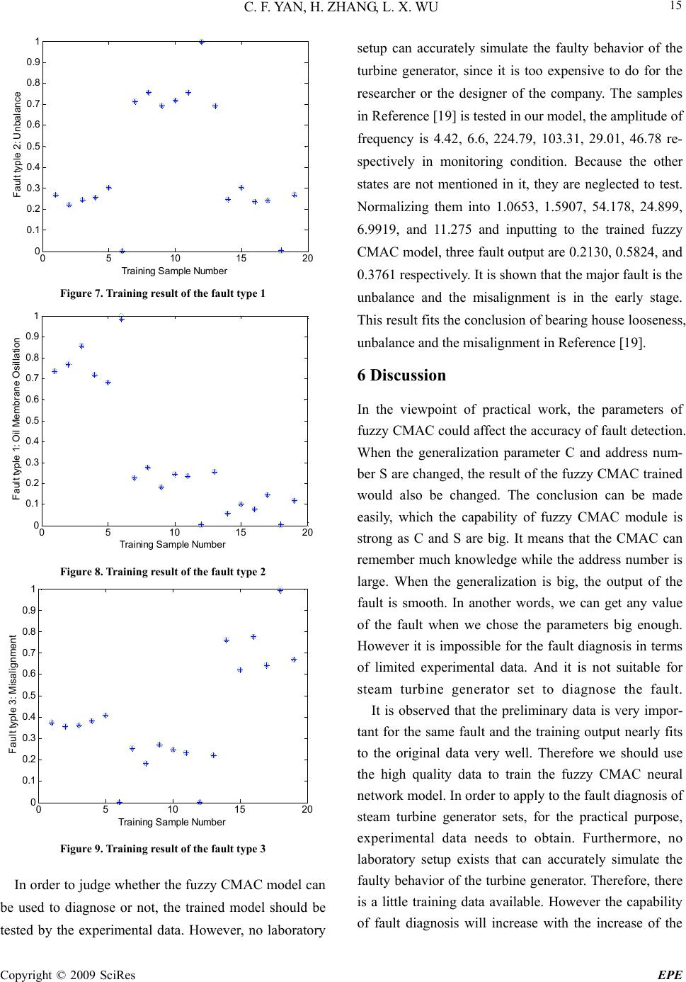 C. F. YAN, H. ZHANG, L. X. WU Copyright © 2009 SciRes EPE 15 05 10 1520 0 0.1 0.2 0.3 0.4 0.5 0.6 0.7 0.8 0.9 1 Trainin g Sam p le Number Fault typle 2: Unbalance Figure 7. Training result of the fault type 1 05 10 1520 0 0.1 0.2 0.3 0.4 0.5 0.6 0.7 0.8 0.9 1 Training Sample Number Fault typle 1: Oil Membrane Osillation Figure 8. Training result of the fault type 2 05 10 1520 0 0.1 0.2 0.3 0.4 0.5 0.6 0.7 0.8 0.9 1 Training Sample Number Fault typle 3: Misalignment Figure 9. Training result of the fault type 3 In order to judge whether the fuzzy CMAC model can be used to diagnose or not, the trained model should be tested by the experimental data. However, no laboratory setup can accurately simulate the faulty behavior of the turbine generator, since it is too expensive to do for the researcher or the designer of the company. The samples in Reference [19] is tested in our model, the amplitude of frequency is 4.42, 6.6, 224.79, 103.31, 29.01, 46.78 re- spectively in monitoring condition. Because the other states are not mentioned in it, they are neglected to test. Normalizing them into 1.0653, 1.5907, 54.178, 24.899, 6.9919, and 11.275 and inputting to the trained fuzzy CMAC model, three fault output are 0.2130, 0.5824, and 0.3761 respectively. It is shown that the major fault is the unbalance and the misalignment is in the early stage. This result fits the conclusion of bearing house looseness, unbalance and the misalignment in Reference [19]. 6 Discussion In the viewpoint of practical work, the parameters of fuzzy CMAC could affect the accuracy of fault detection. When the generalization parameter C and address num- ber S are changed, the result of the fuzzy CMAC trained would also be changed. The conclusion can be made easily, which the capability of fuzzy CMAC module is strong as C and S are big. It means that the CMAC can remember much knowledge while the address number is large. When the generalization is big, the output of the fault is smooth. In another words, we can get any value of the fault when we chose the parameters big enough. However it is impossible for the fault diagnosis in terms of limited experimental data. And it is not suitable for steam turbine generator set to diagnose the fault. It is observed that the preliminary data is very impor- tant for the same fault and the training output nearly fits to the original data very well. Therefore we should use the high quality data to train the fuzzy CMAC neural network model. In order to apply to the fault diagnosis of steam turbine generator sets, for the practical purpose, experimental data needs to obtain. Furthermore, no laboratory setup exists that can accurately simulate the faulty behavior of the turbine generator. Therefore, there is a little training data available. However the capability of fault diagnosis will increase with the increase of the 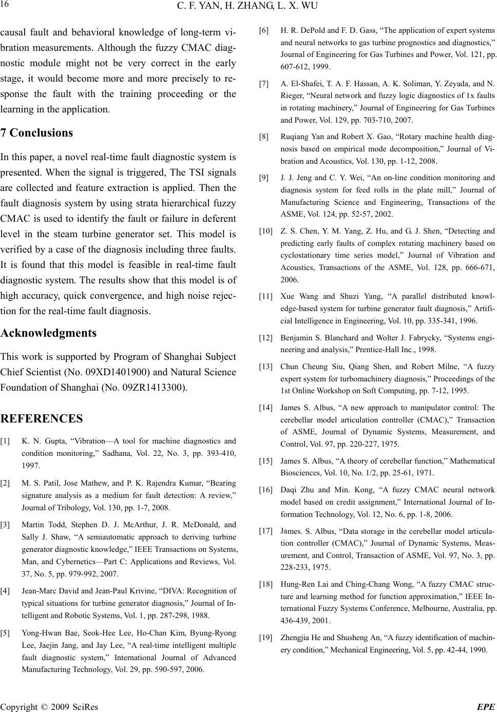 C. F. YAN, H. ZHANG, L. X. WU Copyright © 2009 SciRes EPE 16 causal fault and behavioral knowledge of long-term vi- bration measurements. Although the fuzzy CMAC diag- nostic module might not be very correct in the early stage, it would become more and more precisely to re- sponse the fault with the training proceeding or the learning in the application. 7 Conclusions In this paper, a novel real-time fault diagnostic system is presented. When the signal is triggered, The TSI signals are collected and feature extraction is applied. Then the fault diagnosis system by using strata hierarchical fuzzy CMAC is used to identify the fault or failure in deferent level in the steam turbine generator set. This model is verified by a case of the diagnosis including three faults. It is found that this model is feasible in real-time fault diagnostic system. The results show that this model is of high accuracy, quick convergence, and high noise rejec- tion for the real-time fault diagnosis. Acknowledgments This work is supported by Program of Shanghai Subject Chief Scientist (No. 09XD1401900) and Natural Science Foundation of Shanghai (No. 09ZR1413300). REFERENCES [1] K. N. Gupta, “Vibration—A tool for machine diagnostics and condition monitoring,” Sadhana, Vol. 22, No. 3, pp. 393-410, 1997. [2] M. S. Patil, Jose Mathew, and P. K. Rajendra Kumar, “Bearing signature analysis as a medium for fault detection: A review,” Journal of Tribology, Vol. 130, pp. 1-7, 2008. [3] Martin Todd, Stephen D. J. McArthur, J. R. McDonald, and Sally J. Shaw, “A semiautomatic approach to deriving turbine generator diagnostic knowledge,” IEEE Transactions on Systems, Man, and Cybernetics—Part C: Applications and Reviews, Vol. 37, No. 5, pp. 979-992, 2007. [4] Jean-Marc David and Jean-Paul Krivine, “DIVA: Recognition of typical situations for turbine generator diagnosis,” Journal of In- telligent and Robotic Systems, Vol. 1, pp. 287-298, 1988. [5] Yong-Hwan Bae, Seok-Hee Lee, Ho-Chan Kim, Byung-Ryong Lee, Jaejin Jang, and Jay Lee, “A real-time intelligent multiple fault diagnostic system,” International Journal of Advanced Manufacturing Technology, Vol. 29, pp. 590-597, 2006. [6] H. R. DePold and F. D. Gass, “The application of expert systems and neural networks to gas turbine prognostics and diagnostics,” Journal of Engineering for Gas Turbines and Power, Vol. 121, pp. 607-612, 1999. [7] A. El-Shafei, T. A. F. Hassan, A. K. Soliman, Y. Zeyada, and N. Rieger, “Neural network and fuzzy logic diagnostics of 1x faults in rotating machinery,” Journal of Engineering for Gas Turbines and Power, Vol. 129, pp. 703-710, 2007. [8] Ruqiang Yan and Robert X. Gao, “Rotary machine health diag- nosis based on empirical mode decomposition,” Journal of Vi- bration and Acoustics, Vol. 130, pp. 1-12, 2008. [9] J. J. Jeng and C. Y. Wei, “An on-line condition monitoring and diagnosis system for feed rolls in the plate mill,” Journal of Manufacturing Science and Engineering, Transactions of the ASME, Vol. 124, pp. 52-57, 2002. [10] Z. S. Chen, Y. M. Yang, Z. Hu, and G. J. Shen, “Detecting and predicting early faults of complex rotating machinery based on cyclostationary time series model,” Journal of Vibration and Acoustics, Transactions of the ASME, Vol. 128, pp. 666-671, 2006. [11] Xue Wang and Shuzi Yang, “A parallel distributed knowl- edge-based system for turbine generator fault diagnosis,” Artifi- cial Intelligence in Engineering, Vol. 10, pp. 335-341, 1996. [12] Benjamin S. Blanchard and Wolter J. Fabrycky, “Systems engi- neering and analysis,” Prentice-Hall Inc., 1998. [13] Chun Cheung Siu, Qiang Shen, and Robert Milne, “A fuzzy expert system for turbomachinery diagnosis,” Proceedings of the 1st Online Workshop on Soft Computing, pp. 7-12, 1995. [14] James S. Albus, “A new approach to manipulator control: The cerebellar model articulation controller (CMAC),” Transaction of ASME, Journal of Dynamic Systems, Measurement, and Control, Vol. 97, pp. 220-227, 1975. [15] James S. Albus, “A theory of cerebellar function,” Mathematical Biosciences, Vol. 10, No. 1/2, pp. 25-61, 1971. [16] Daqi Zhu and Min. Kong, “A fuzzy CMAC neural network model based on credit assignment,” International Journal of In- formation Technology, Vol. 12, No. 6, pp. 1-8, 2006. [17] James. S. Albus, “Data storage in the cerebellar model articula- tion controller (CMAC),” Journal of Dynamic Systems, Meas- urement, and Control, Transaction of ASME, Vol. 97, No. 3, pp. 228-233, 1975. [18] Hung-Ren Lai and Ching-Chang Wong, “A fuzzy CMAC struc- ture and learning method for function approximation,” IEEE In- ternational Fuzzy Systems Conference, Melbourne, Australia, pp. 436-439, 2001. [19] Zhengjia He and Shusheng An, “A fuzzy identification of machin- ery condition,” Mechanical Engineering, Vol. 5, pp. 42-44, 1990. |