 Journal of Software Engineering and Applications, 2011, 4, 417-425 doi:10.4236/jsea.2011.47048 Published Online July 2011 (http://www.SciRP.org/journal/jsea) Copyright © 2011 SciRes. JSEA 417 Employing Two “Sandwich Delay” Mechanisms to Enhance Predictability of Embedded Systems Which Use Time-Triggered Co-operative Architectures Mouaaz Nahas Department of Electrical Engineering, College of Engineering and Islamic Architecture, Umm Al-Qura University, Makkah, KSA. Email: mmnahas@uqu.edu.sa Received June 1st, 2011; revised June 29th, 2011; accepted July 6th, 2011. ABSTRACT In many real-time resource-constrained embedded systems, highly-predictable system behavior is a key design re- quirement. The “time-triggered co-operative” (TTC) scheduling algorithm provides a good match for a wide range of low-cost embedded applications. As a consequence of the resource, timing, and power constraints, the implementation of such algorithm is often fa r from trivia l. Th us, basic implementation of TTC algorithm can result in excessive levels of task jitter which may jeopardize the predictability of many time-critical applications using this algorithm. This paper discusses the main sources of jitter in earlier TTC implementations and develops two alternative implementations – based on the employment of “sandwich delay” (SD) mechanisms – to reduce task jitter in TTC system significantly. In addition to jitter levels at task release times, we also assess the CPU, memory and power requirements involved in practical implementations of the proposed schedulers. The paper concludes that the TTC scheduler implementation using “multiple timer interrup t” (MTI) technique achieves better performance in terms of timing behavior and resource utilization as opposed to th e other implementation which is ba sed on a simple SD mechanism. Use of MTI technique is also found to provide a simple solution to “task overrun” problem which may degrade the performance of many TTC systems. Keywords: Time-Triggered, Co-Operative, Cyclic Executive, Jitter, Sandwich Delay, Multiple Timer Interrupts, Tas k Overrun 1. Introduction Embedded systems are often implemented as a collec- tion of communicating tasks [1]. The various possible system architectures can then be characterized according to these tasks. For example, if the tasks are invoked as a response to aperiodic events, the system architecture is described as “event-triggered” [2,3]. Alternatively, if the tasks are invoked periodically u nder the control of timer, the system architecture is described as “time-triggered” [3,4]. Since highly-predictable system behavior is an important design requirement for many embedded sys- tems, time-triggered software architectures have become the subject of considerable attention (e.g. see [4]). In particular, it has been widely accepted that time-triggered architectures are a good match for many safety-critical applications, since they help to improve the ov erall safety and reliability [5-10]. In contrast with the event-trigg ered, time-triggered systems are easy to validate, verify, test, and certify because the times related to tasks are de- terministic [11,12]. Moreover, embedded systems can also be character- iz ed ac co r d in g to the natures of their tasks. For example, if the tasks – once invoked – can pre-empt (interrupt) other tasks, then the system is described as “pre-emptive”. If, instead, tasks cannot be interrupted, the system is de- scribed as “non pre-emptive” or “co-operative”. When comparing with pre-emptive, many researchers demon- strated that co-operative schedulers have numerous de- sirable features, particularly for use in safety-related sys- tems [2,5 ,7,13,14]. Cyclic executive is a form of co-operative scheduler that has a time-triggered architecture. In such “time- triggered co-operative” (TTC) architectures, tasks exe- cute in a sequential order defined prior to system activa-  Employing Two “Sandwich Delay” Mechanisms to Enhance Predictability of Embedded Systems Which Use 418 Time-Triggered Co-operative Architectures tion; the number of tasks is fixed; each task is allocated an execution slot (called a minor cycle or a fram e) during which the task executes; the task – once interleaved by the scheduler – can execute until completion without interruption from other tasks; all tasks are periodic and the deadline of each task is equal to its period; the worst-case execution time of all tasks is known; there is no context switching between tasks; and tasks are sched- uled in a repetitive cycle called major cycle [15,16]. Provided that an appropriate implementation is used, TTC schedulers can be a good match for a broad range of embedded applications, even those which have hard real-time requirements [15-21]. Overall, a TTC scheduler can be easily constructed using only a few hundred lines of highly portable code on high-level programming lan- guages (such as “C”), while th e resulting system is high- ly-predictable [14]. Since all tasks in TTC scheduler are executed regularly according to their predefined order, such schedulers demonstrate v ery low levels of task jitter [16,22,23] and can maintain their low-jitter characteris- tics even when complex techniques, such as “dynamic voltage scaling” (DVS), are employed to reduce system power consumption [20]. Despite many advantages, implementing the software code of TTC algor ithm, with less care, can result in dem- onstrating high levels of task jitter especially at the release times of low-priority tasks. The presence of jitter can have a detrimental impact on the performance of many em- bedded applications. For example, [24] show that – dur- ing data acquisition tasks – jitter rates of 10% or more can introduce errors which are so significant that any subse- quent interpretation of the sampled signal may be ren- dered meaningless. Similarly [25] discusses the serious impact of jitter on applications such as spectrum analysis and filtering. In embedded control systems, jitter can greatly degrade the performance by varying the sampling period [26,27]. Moreover, in applications – like distrib- uted multimedia communications – the presence of even low amounts of jitter may result in a severe degradation in perceptual video quality [28]. The present study is concerned with implementing highly-predictable embedded systems. Predictability is one of the most important objectives of real-time em- bedded systems [20,29-31]. Ideally, predictability means that the system is able to determine, in advance, exactly what the system will do at every moment of time in which it is running and hence determine whether the system is capable of meeting all its timing constraints. One way in which predictable behavior manifests itself is in low levels of task jitter. The main aim of this paper is to address the problem of task jitter to enhance predictability of embedded ap- plications employing TTC architectures. In particular, the paper discusses the main sources of jitter in the original TTC systems and proposes two new TTC scheduler im- plementations which have the potential to reduce task jitter by means of employing “sandwich delay” (SD) me- chanisms [32]. Such implementations will be referred to as TTC-SD and TTC-MTI schedulers. The remaining parts of the paper are organized as fol- lows. Section 2 reviews basic TTC scheduler implemen- tations and highlights their main drawbacks with regards to jitter behavior. In Section 3, we describe the TTC-SD and TTC-MTI schedulers. Section 4 outlines the experi- mental methodology used to evaluate the described schedulers and provides the results in terms of task jitter and implementation costs (i. e. resource requirements). We finally draw the overall paper conclusions in Section 5. 2. Basic Implementations of TTC Scheduler This section describes the implementation of the “origi- nal TTC-Dispatch” scheduler [14] and discusses its main limitations. 2.1. Overview The original TTC-Dispatch scheduler is driven by peri- odic interrupts generated from an on-chip timer. When an interrupt occurs, the processor executes an Interrupt Ser- vice Routine (ISR) Update function. In the Update func- tion, the scheduler checks the status of all tasks to see which tasks are due to run and sets appropriate flags. After these checks are co mplete, a Dispatch function will be called, and the identified tasks (if any) will be exe- cuted in sequence. The Dispatch function is called from an “endless” loop placed in the Main code and when not executing the Update and Dispatch functions, the system will usually enter a low-power “idle” mode. This process is illustrated schematically in Figure 1. Note that such a scheduler has previously been referred to as TTC- Dispatch scheduler [33]. Despite that TTC schedulers provide a simple, low-cost and highly-predictable software platform for many embedded applications, such a basic implementa- tion of the TTC scheduler can introduce high levels of jitter at task release times [34]. This point is further dis- cussed as follows. 2.2. Task Jitter In periodic tasks, variations in the interval between the release times are termed jitter. As previously noted, the presence of jitter can – in many systems – result in less predictable operation and cause a detrimental impact on the system performance. Since our focus in this paper is Copyright © 2011 SciRes. JSEA  Employing Two “Sandwich Delay” Mechanisms to Enhance Predictability of Embedded Systems Which Use 419 Time-Triggered Co-operative Architectures Main ()Sleep ()Task ()Dispatch ()Update () Figure 1. Function call tree for the original TTC scheduler. on TTC schedulers, we identify the following three pos- sible sources of task jitter in such systems. 1) Scheduling overhead variation The overhead of a conventional scheduler arises mainly from context switching. In some systems, such as those employing DVS [20], the scheduling overhead is com- paratively large and may have a highly-variable duration. Figure 2 illustrates how a TTC system can suffer release jitter as a result of variations in the scheduler overh e ad. In [34], we observed that the underlying cause of this variation in the original TTC-Dispatch scheduler is the interrupt behavior. For exam ple, when an inte rrupt occurs, the processor takes fixed time to leave the “idle” mode and begin to execute the ISR Update. However, in the Update, and before calling Dispatch, the scheduler goes through the task list and identifies which task is due to run. Such check activities cannot be fixed in time if there is more than one schedule d tas k t o run. I n or de r to deal wi t h this problem, a “modified TTC-Dispatch” scheduler has been d ev eloped [34]. The propos ed sc he dul e r cont rols the jitter in the first task (which is implicitly the “top priority” task with hardest timing constraints) by re-arranging the activities performed in the Update and Dispatch functions. Specifically, the Update function is very short and has a fixed duration: it simply keeps track of the number of Ticks. The dispatch activities will then be carried out in the Dispatch function. By doing so, we make sure that the first task in the system is always free of jitter. Note that the function call tree for the modified TTC-Dispatch sched- uler is same as the original TTC-Dispatch scheduler (Figure 1). 2) Task placement Even if we can avoid variations in the scheduler over- head, we may still have problems with jitter in a TTC scheduler as a result of the task placement. To illustrate this, consider Figure 3. In this schedule, Task C runs sometimes after A, sometimes after A and B, and sometimes alone. Therefore, the period between every two successive runs of Task C is highly variable. Such a variation can be called “schedule-induced” jitter. More- over, if Task A and Task B have variable execution dura- tions, then the jitter levels of Task C will even be larger. This type of jitter is called “task-induced” jitter. The original and modified TTC-Dispatch schedulers are not capable of dealing with jitter caused by the task place- ment. 3) Tick drift For completeness, we also consider tick drift as a source of task jitter. In the TTC designs considered in this paper, a cl ock t ick is gene rated by a ha rdware tim er that i s linked to an ISR. This mechanism relies on the presence of a timer that runs at a fixed frequency: in these circum- stances, any jitter will arise from variations at the hard- ware level (e.g. through the use of a low-cost frequency source, such as a ceramic resonator, to drive the on-chip oscillator: see [14]). In the scheduler implementations considered in this paper, the software developer has no control over the clock source. However, in some circumstances, those implementing a scheduler must take such factors into account. For example, in situations where DVS is employed (to Speed Over head Task OverheadTask Task Period OverheadTask Over head Task Task Period Task Period Figure 2. Release jitter caused by variation of scheduling overhead. Speed Task ATask C Task Period Task Period Task Period Task CTask ATask C Task BTask C Task B Figure 3. Release jitter caused by task placement in TTC schedulers. Copyright © 2011 SciRes. JSEA  Employing Two “Sandwich Delay” Mechanisms to Enhance Predictability of Embedded Systems Which Use 420 Time-Triggered Co-operative Architectures reduce CPU power consumption), it may take a variable amount of time for the processor’s Phase-Locked Loop (PLL) to stabilize after the clock frequency is cha nged. As discussed elsewhere, it is possib le to compensate for such changes in software and thereby reduce jitter (see [20]). Such techniques are not considered further in this paper. 3. Modified implementations of TTC Scheduler Our concern in this paper is o n jitter caused mainly by the task placement. To reduce this type of jitter, we introduce two techniques which can be in corporated in the basic TTC scheduler framework. These techniques are described here. 3.1. Adding “Sandwich Delays” One way to reduce the variation in the starting times of “low-priority” tasks in TTC system is to place “Sandwich Delay” (SD) [32] around t asks which execute prior to other tasks in the same tick interval. Such a modified TTC scheduler implementation will be referred to as TTC-SD scheduler. In the TTC-SD scheduler, sandwich delays are used to provide execution “slots” of fixed sizes in situations where there is more than one task in a tick interval. To clarify this, consider the set of tasks shown in Figure 4. In the figure, the required SD prior to Task C – for low jitter behavior – is equal to the estimated “worst-case execution time” (WCET) of Task A plus Task B. This implies that in the second tick (for example), the scheduler runs Task A and then waits for the period equals to the WCET of Task B before running Task C. The figure shows that when SDs are used, the periods between any successive runs of Task C become equal and hence jitter in the release time of this task is significantly reduced. Note that – with this implementation – estimated WCET for each task is input to the scheduler through a function placed in the Main code. After entering task parameters, the scheduler calculates the scheduler major cycle and the required release tim e for each task. Note that the required release time of a task is the time between the start of the tick interval and the start of the predefined task “slot” plus a little safety margin. 3.2. Working with “Multiple Timer Interrupts” Although the use of SD can help to reduce jitter in low-priority tasks significantly, this approach does not give such a precise control over timing and can signifi- cantly increase the levels of CPU power consumption. This is because the processor is forced to run in normal operating mode while the SD is executing. To address both problems, a modified sandwich delay mechanism that uses “Multiple Timer Interrupt” (MTI) is developed. The TTC scheduler incorporating MTI technique will be referred to as TTC-MTI scheduler. In the TTC-MTI scheduler, several timer interrupts are used to generate the predefined execution “slots” for tasks. This allows more precise control of timing in situations where more than one task executes in a given tick interval. The use of interrupts also allows the processor to enter an “idle” mode after completion of each task, resulting in power saving. To implement this technique, two interrupts are re- quired: Tick interrupt: to generate the scheduler periodic tick. Task interrupt: to trigger the execu tion of tasks within tick intervals. The complete process is illustrated in Figure 5. In this figure, to achieve zero jitter, the required release time prior to Task C (for example) is equal to the WCET of Task A plus t he WCET of Task B pl us scheduler ove rhead (i.e. ISR Update function). This implies that in the second tick (for example), after running the ISR, the scheduler waits – in the “idle” mode – for a period of time equals to the WCETs of Task A an d Task B bef ore runni ng Tas k C. Figure 5 shows that with the MTI technique, the periods Ta sk ATask C as Period Task C Ta sk B t (Ticks)t = 012 as Period Ta sk C Tic Interrupt Idle Mode SDSD SD Ta sk A Figure 4. Using Sandwic h Delays to reduce release jitter in TTC schedulers. A C Task C Peri od CB B Time Tick 0Tick 1Tick 2 Task C Peri od C Tic k Interrupt Task Interrupts Idle Mode Idle Mode I S R I S R I S R Idle Mode Figure 5. Using MTIs to reduce release jitter in TTC schedulers. Copyright © 2011 SciRes. JSEA  Employing Two “Sandwich Delay” Mechanisms to Enhance Predictability of Embedded Systems Which Use 421 Time-Triggered Co-operative Architectures between the successive runs of Task C (the “lowest pri- ority” task) are always equal. This means that the task jitter in such implementation is independent on the task placement or the duration(s) of the preceding task(s). In fact, the method described here requires no more than two timers or one timer – with multiple channels – in total. The hardware used in this study to implement this scheduler (Section 4.1) supports multiple channels per timer, allowing efficient use of the available resources. In the TTC-MTI, the estimated WCET for each task is also input to the scheduler through the Main code. The scheduler then calculates the scheduler major cycle and the required release time for each task. Moreover, there is no Dispatch called in the Main code: instead, “interrupt request wrappers” – which contain Assembly code – are used to manage the sequence of operation in the whole scheduler. The function call tree for the TTC-MTI sche- duler is shown in Figure 6. Unlike the normal Dispatch schedulers, the TTC-MTI implementation relies on two interrupt Update functions: Tick Update and Task Update. The Tick Update – which is called every tick interval (as normal) – identifies which tasks are ready to execute within the cu rrent tick interval. Before placing the processor in the “idle” mode, the Tick Update function sets the match register of the task timer according to the release time of the first due task running in the current interval. Calculating the release time of the first task in the system takes into account the WCET of the Tick Update code. When the task interrupt occurs, the Task Update sets the return address to the task that will be executed straight after this update function, and sets the match register of the task timer for the next task (if any). The scheduled task then executes as normal. Once the task completes execu- tion, the processor enters “idle” mode and waits for the next task interrupt or tick interrupt (depending on the task schedule). Note that the Task Update code has fixed ex- ecution duration to avoid jitter at the starting time of tasks. Furthermore, it is worth noting that the TTC-MTI scheduler also provides a simple solution to “task over- run” probl em in TTC syst em which m ay – in m any cases – have serious impacts on system behavior [35]. More spe- cifically, the integrated MTI technique helps the TTC scheduler to shutdown any task exceeding its estimated “worst-case execution time” (WCET) [36]. In the im- plementation considered, if the ov errunning task is follo- wed by another task in the same tick, then the task inter- rupt – which triggers the execution of the latter task – will immediately terminate the overrun. Otherwise, the task is allowed to overrun until the next tick interrupt where a new tick will be launched. Please no te that this issue will not be discussed further in this paper. 4. Evaluating the TTC-SD and TTC-MTI Schedulers This section first outlines the experimental methodology used to eval uat e t he TT C-SD and TTC -MTI sche duler s. I t then presents the output results in terms of task jitter and implementation co sts. Note that the results obtained from the new schedulers are compared with those obtained from the “modified TTC-Dispatch” scheduler [34] to highlight the impact of the proposed schedulers on the low-priority task jitter. 4.1. Experimental Methodology We first outline the experimental methodology used to obtain the results presented in this section. 1) Hardware platform The empirical studies reported in this paper were con- ducted using Ashling LPC2000 evaluation board sup- porting Philips LPC2106 pro cessor [37]. The LPC2106 is a modern 32-bit microcontroller with an ARM7 core which can run – under control of an on-chip PLL – at frequencies from 12 MHz to 60 MHz [38]. The oscillator frequency used was 12 MHz, and a CPU frequency was 60 MHz. The compiler used was the GCC ARM 4.1.1 oper- ating in Windows by means of Cygwin (a Linux emulator for windows). The IDE and simulator used was the Keil ARM development kit (v 3.12). 2) Jitter test For meaningful comparison of jitter results, the fol- lowing task set was used (Figure 7). To allow exploring the impact of schedule-induced j itter, Task A was sched- uled to run every two ticks. Moreover, all tasks were set to have variable execution durations to allow exploring the impact of task-induced jitter. Note that the duration of Task A is dou ble the durati on of Task B and Task C. Also, Task A has the highest priority and Task C has the lowest priority. Jitter was measured at the release time of each task. To measure jitter experimentally, we set a pin high at the beginning of the task (for a short time) and then measure Main ()Tick Update ()Sleep ()Task Update ()Task ()Sleep () If Task () is not the last due task in the tick If Task () is the last due task in the tick Figure 6. Function call tree for the TTC-MTI scheduler. Copyright © 2011 SciRes. JSEA 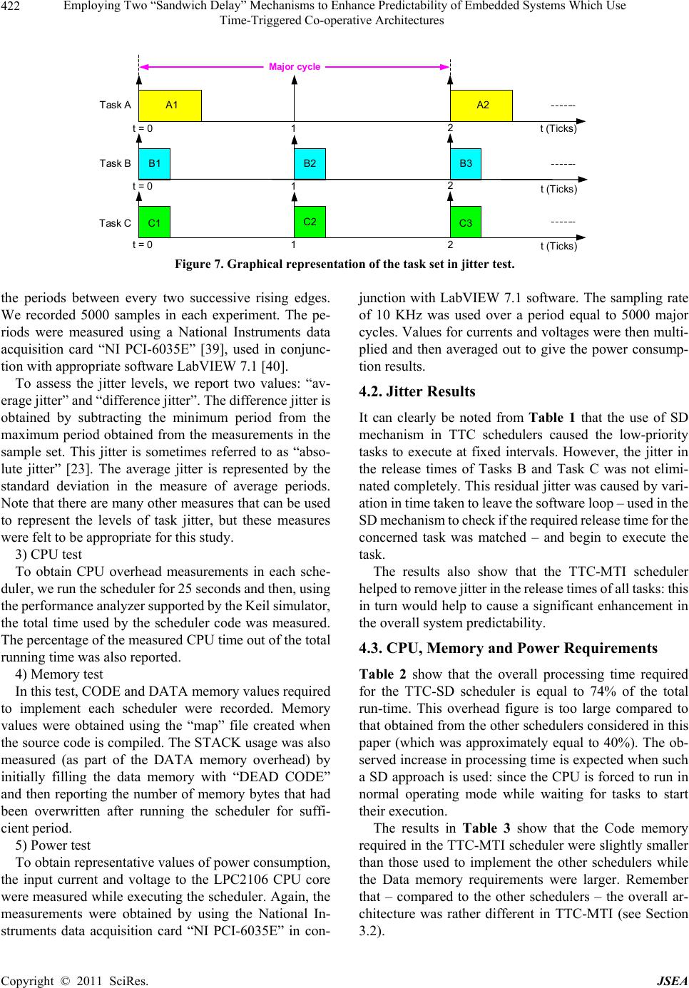 Employing Two “Sandwich Delay” Mechanisms to Enhance Predictability of Embedded Systems Which Use 422 Time-Triggered Co-operative Architectures B1 A1 B2 C1 t = 01 C2 t = 01 t (Ticks) t = 01 Task A Task B Tas k C t (Ticks) t (Ticks) Major cycle B3 A2 C3 2 2 2 Figure 7. Graphical representation of the task set in jitter test. the periods between every two successive rising edges. We recorded 5000 samples in each experiment. The pe- riods were measured using a National Instruments data acquisition card “NI PCI-6035E” [39], used in conjunc- tion with appropriate software LabV IEW 7.1 [40]. To assess the jitter levels, we report two values: “av- erage jitter” and “difference jitter”. The difference jitter is obtained by subtracting the minimum period from the maximum period obtained from the measurements in the sample set. This jitter is sometimes referred to as “abso- lute jitter” [23]. The average jitter is represented by the standard deviation in the measure of average periods. Note that there are many other measures that can be used to represent the levels of task jitter, but these measures were felt to be appropriate for this study. 3) CPU test To obtain CPU overhead measurements in each sche- duler, we ru n the sc heduler for 2 5 secon ds and t hen, usi ng the performance analyzer s upported by the Keil simulator, the total time used by the scheduler code was measured. The percentage of the measured CPU time out of the total running time was also reported. 4) Memory test In this test, CODE and DATA memory values required to implement each scheduler were recorded. Memory values were obtained using the “map” file created when the source code is compiled. The STACK usage was also measured (as part of the DATA memory overhead) by initially filling the data memory with “DEAD CODE” and then reporting the number of memory bytes that had been overwritten after running the scheduler for suffi- cient period. 5) Power test To obtain represen tative v alues of p ower con su mption, the input current and voltage to the LPC2106 CPU core were measured while executing the scheduler. Again, the measurements were obtained by using the National In- struments data acquisition card “NI PCI-6035E” in con- junction with LabVIEW 7.1 software. The sampling rate of 10 KHz was used over a period equal to 5000 major cycles. Values for currents and voltage s were then multi- plied and then averaged out to give the power consump- tion results. 4.2. Jitter Results It can clearly be noted from Table 1 that the use of SD mechanism in TTC schedulers caused the low-priority tasks to execute at fixed intervals. However, the jitter in the release times of Tasks B and Task C was not elimi- nated completely. This residual jitter was caused by vari- ation in time taken to leave the software loop – used in the SD mechanism to check if the req uired release tim e for the concerned task was matched – and begin to execute the task. The results also show that the TTC-MTI scheduler helped to remove jitter in the release times of all tasks: this in turn would help to cause a significant enhancement in the overall system predictab ility. 4.3. CPU, Memory and Power Requirements Table 2 show that the overall processing time required for the TTC-SD scheduler is equal to 74% of the total run-time. This overhead figure is too large compared to that obtained from the other schedulers considered in this paper (which was approximately equal to 40%). The ob- served increase in pro cessing time is expected when such a SD approach is used: since the CPU is forced to run in normal operating mode while waiting for tasks to start their execution. The results in Table 3 show that the Code memory required in the TTC-MTI scheduler were slightly smaller than those used to implement the other schedulers while the Data memory requirements were larger. Remember that – compared to the other schedulers – the overall ar- chitecture was rather different in TTC-MTI (see Section 3.2). Copyright © 2011 SciRes. JSEA 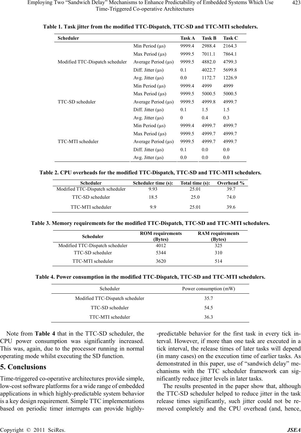 Employing Two “Sandwich Delay” Mechanisms to Enhance Predictability of Embedded Systems Which Use 423 Time-Triggered Co-operative Architectures Table 1. Task jitter from the modified TTC-Dispatch, TTC-SD and TTC-MTI schedulers. Scheduler Task ATask BTask C Min Period (µs) 9999.42988.42164.3 Max Period (µs) 9999.57011.17864.1 Average Period (µs)9999.54882.04799.3 Diff. Jitter (µs) 0.1 4022.75699.8 Modified TTC-Dispatch scheduler Avg. Jitter (µs) 0.0 117 2 . 71226.9 Min Period (µs) 9999.44999 4999 Max Period (µs) 9999.55000.55000.5 Average Period (µs)9999.54999.84999.7 Diff. Jitter (µs) 0.1 1.5 1.5 TTC-SD scheduler Avg. Jitter (µs) 0 0.4 0.3 Min Period (µs) 9999.44999.74999.7 Max Period (µs) 9999.54999.74999.7 Average Period (µs)9999.54999.74999.7 Diff. Jitter (µs) 0.1 0.0 0.0 TTC-MTI scheduler Avg. Jitter (µs) 0.0 0.0 0.0 Table 2. CPU overheads for the modifie d TTC-Dispatch, TTC-SD and TTC-MTI schedule r s. Scheduler Scheduler time (s):Total time (s):Overhead % Modified TTC-Dispat ch s cheduler9.93 25.01 39.7 TTC-SD scheduler 18.5 25.0 74.0 TTC-MTI scheduler 9.9 25.01 39.6 Table 3. Memory requirements for the modified TTC-Dispatch, TTC-SD and TTC-MTI schedulers. Scheduler ROM requirements (Bytes) RAM requirements (Bytes) Modified TTC-Dispatch scheduler 4012 325 TTC-SD scheduler 5344 310 TTC-MTI scheduler 3620 514 Table 4. Power consumption in the modified TTC-Dispatch, TTC-SD and TTC-MTI schedulers. Scheduler Power consumption (mW) Modified TTC-Dispatch scheduler 35.7 TTC-SD scheduler 54.5 TTC-MTI scheduler 36.3 Note from Table 4 that in the TTC-SD scheduler, the CPU power consumption was significantly increased. This was, again, due to the processor running in normal operating mode whilst executin g the SD function. 5. Conclusions Time-triggered co-ope rat i ve architectu res p r ovide simple, low-cost so ftware platform s for a wide ra nge of emb edded applications in which highly-predictable system behavior is a key design requirement. Simple TTC implementations based on periodic timer interrupts can provide highly- -predictable behavior for the first task in every tick in- terval. However, if more than one task are executed in a tick interval, the release times of later tasks will depend (in many cases) on the execution time of earlier tasks. As demonstrated in this paper, use of “sandwich delay” me- chanisms with the TTC scheduler framework can sig- nificantly reduce jitter levels in later tasks. The results presented in the paper show that, although the TTC-SD scheduler helped to reduce jitter in the task release times significantly, such jitter could not be re- moved completely and the CPU overhead (and, hence, Copyright © 2011 SciRes. JSEA  Employing Two “Sandwich Delay” Mechanisms to Enhance Predictability of Embedded Systems Which Use 424 Time-Triggered Co-operative Architectures system powe r consumptio n) was increased. Theref ore, the TTC-MTI scheduler was developed to provide a better solution where all tasks became free of jitter while the system maintained its low CPU overhead and power re- quirements. The TTC-MTI scheduler achieved this per- formance by using multiple timers to adjust the timing for tick and tasks and also utilizing the “id le” mode when th e processor is not executing tasks or ISR functions. More- over, the TTC-MTI scheduler has the potential to over- come the problem of task overrun, thereby increasing the overall system predictability. Finally, it is important for embedded software devel- opers who decide to employ any of the described tech- niques or adapt them for use in their existing designs to take into account the implementation costs (in terms of CPU, memory and power resources) in addition to the maximum levels of jitter that each task in the system can tolerate. 6. Acknowledgements The work described in this paper was carried out in the Embedded Systems Laboratory (ESL) at University of Leicester, UK, under the supervision of Professor Mi- chael Pont, to whom the author is thankful. The author also thanks Dr. Zemian Hughes for his valuable assis- tance in creating the software code for the TTC-MTI scheduler. REFERENCES [1] A. C. Shaw, “Real-Time Systems and Software,” John Wiley & Sons Inc., New York, 2001. [2] N. Nissanke, “Real-time Systems,” Prentice-Hall, Upper Saddle River, 1997. [3] A. Albert, “Comparison of Event-Triggered and Time- -Triggered Concepts with Regard to Distributed Control Systems,” Proceedings of Embedded World, Nurnberg, 17-19 February 2004, pp. 235-252. [4] H. Kopetz, “Real-Time Systems: Design Principles for Distributed Embedded Applications,” Kluwer Academic, Boston, 1997. [5] S. T. Allworth, “An Introduction to Real-Time Software Design,” Macmillan, London, 1981. [6] N. Storey, “Saf ety-Critical Co mputer Systems,” Addison- Wesley, Boston, 1996. [7] I. Bates, “Introduction to Scheduling and Timing Analy- sis,” The Use of Ada in Real-Time System, IEE Confer- ence Publication 00/034, 2000. [8] R. Obermaisser, “Event-Triggered and Time-Triggered Control Paradigms,” Kluwer Academic, Boston, 2004. [9] B. Zhang, “Specifying and Verifying Timing Properties of a Time-Triggered Protocol for in-Vehicle Communica- tion,” 9th ACIS International Conference on Software Engineering, Artificial Intelligence, Networking, and Pa- rallel/Distributed Computing, Phuket, 6-8 August 2008, pp. 467-472. doi:10.1109/SNPD.2008.99 [10] J. Zhang, F. Xiang, B. Wang and J. Lu, “An Extensible Software Framework for Reliable Distributed Embedded System Modelling,” 2nd International Asia Conference on Informatics in Control, Automation and Robotics, Wuhan, 6-7 March 2010, pp. 234-237. doi:10.1109/CAR.2010.5456558 [11] F. Scheler and W. Schröder-Preikschat, “The RTSC: Le- veraging the Migration from Event-Triggered to Time- Triggered Systems,” 13th IEEE International Symposium on Object/Component/Service-Oriented Real-Time Dis- tributed Computing, Carmona, 5-6 May 2010, pp. 34- 41. [12] J. W. S. Liu, “Real-Time Systems,” Prentice Hall, Upper Saddle River, 2000. [13] N. J. Ward, “The Static Analysis of a Safety-Critical Avionics Control Systems,” Offshore Safety and Reliabil- ity: Sarss’91-Proceedings of the Safety and Reliability Society Symposium, SaRS, Ltd., Roselle, 1991. [14] M. J. Pont, “Patterns for Time-Triggered Embedded Sys- tems: Building Reliable Applications with the 8051 Fam- ily of Microcontrollers,” ACM Press/Addison-Wesley, Boston, 2001. [15] T. P. Baker and A. Shaw, “The Cyclic Executive Model and Ada,” Real-Time Systems, Vol. 1, No. 1, 1989, pp. 7- 25. doi:10.1007/BF02341919 [16] C. D. Locke, “Software Architecture for Hard Real-Time Applications: Cyclic Executives vs. Fixed Priority Execu- tives,” Real-Time Systems, Vol. 4, No. 1, 1992, pp. 37-52. doi:10.1007/BF00365463 [17] M. J. Pont and M. P. Banner, “Designing Embedded Sys- tems Using Patterns: A Case Study,” Journal of Systems and Software, Vol. 71, No, 3, 2004, pp. 201-213. doi:10.1016/S0164-1212(03)00006-2 [18] D. Ayavoo, M. J. Pont and S. Parker, “Does a ‘Simulation First’ Approach Reduce the Effort Involved in the De- velopment of Distributed Embedded Control Systems?” 6th UKACC International Control Conference, Glasgow, 30 August-1 September 2006. [19] T. Nghiem, G. J. Pappas, R. Alur and A. Girard, “Time- Triggered Implementations of Dynamic Controllers,” Proceedings of the 6th ACM & IEEE International Con- ference on Embedded Software, Seoul, 22-2 5 Octo ber 2006, pp. 2-11. [20] T. Phatrapornnant and M. J. Pont, “Reducing Jitter in Embedded Systems Employing a Time-Triggered Soft- ware Architecture and Dynamic Voltage Scaling,” IEEE Transactions on Computers, Vol. 55, No. 2, 2006, pp. 113-124. doi:10.1109/TC.2006.29 [21] M. Short and M. J. Pont, “Fault-Tolerant Time-Triggered Communication Using CAN,” IEEE Transactions on In- dustrial Informatics, Vol. 3, No. 2, 2007, pp. 113-142. doi:10.1109/TII.2007.898477 [22] I. J. Bate, “Scheduling and Timing Analysis for Safety Critical Real-Time Systems,” Ph.D. Dissertation, De- Copyright © 2011 SciRes. JSEA  Employing Two “Sandwich Delay” Mechanisms to Enhance Predictability of Embedded Systems Which Use Time-Triggered Co-operative Archi tectures Copyright © 2011 SciRes. JSEA 425 partment of Computer Science, University of York, Hes- lington, 1998. [23] G. Buttazzo, “Hard Real-Time Computing Systems: Pre- dictable Scheduling Algorithms and Applications,” Sprin- ger, New York, 2005. [24] F. Cottet and L. David, “A Solution to The Time Jitter Removal in Deadline Based Scheduling of Real-Time Applications,” 5th IEEE Real-Time Technology and Ap- plications Symposium, Vancouver, 2-4 June 1999, pp. 33- 38. [25] A. J. Jerri, “The Shannon Sampling Theorem: Its Various Extensions and Applications a Tutorial Review,” Pro- ceedings of the IEEE, Vol. 65, No. 11, 1977, pp. 1565- 1596. doi:10.1109/PROC.1977.10771 [26] M. Torngren, “Fundamentals of Implementing Real-Time Control Applications in Distributed Computer Systems,” Real-Time Systems, Vol. 14, No. 3, 1998, pp. 219-250. doi:10.1023/A:1007964222989 [27] P. Marti, J. M. Fuertes, K. Ramamritham and G. Fohler, “Jitter Compensation for Real-Time Control Systems,” 22nd IEEE Real-Time Systems Symposium, London, 3-6 December 2001, pp. 39-48. [28] S. R. Gulliver and G. Ghinea, “The Perceptual Influence of Multimedia Delay and Jitter,” IEEE International Con- ference on Multimedia and Expo, Beijing, 2-5 July 2007, pp. 2214-2217. doi:10.1109/ICME.2007.4285125 [29] R. E. Kontak, “Applicability of Ada Tasking for Avionics Executives,” Proceedings of the IEEE 1988 National Aerospace and Electronics Conference, Dayton, 23-27 May 1988, Vol. 2, pp. 739-746. [30] J. A. Sta nk ov ic , “ M isc oncep tion s about Real- Time Comp- uting: A Serious Problem for Next-Generation Systems,” Computers, Vol. 21 No. 10, 1988, pp. 10-19. doi:10.1109/2.7053 [31] W. A. Halang and A. D. Stoyenko, “Comparative Evalua- tion of High-Level Real-Time Programming Languages,” Real-Time Systems, Vol. 2, No. 4, 1990, pp. 365-382. doi:10.1007/BF01995678 [32] M. J. Pont, S. Kurian and R. Bautista-Quintero, “Meeting Real-Time Constraints Using ‘Sandwich Delays’,” Trans- actions on Pattern Languages of Programming I, Sprin- ger, Berlin, 2009, pp. 94-102. [33] S. Kurian and M. J. Pont, “Maintenance and Evolution of Resource-Constrained Embedded Systems Created Using Design Patterns,” Journal of Systems and Software, Vol. 80, No. 1, 2007, pp. 32-41. doi:10.1016/j.jss.2006.04.007 [34] M. Nahas, M. J. Pont and A. Jain, “Reducing Task Jitter in Shared-Clock Embedded Systems Using CAN,” In: A. Koelmans, A. Bystrov and M. J. Pont, Eds., Proceedings of the UK Embedded Forum, University of Newcastle upon Tyne, Newcastle, 2004, pp. 184-194. [35] Z. M. Hughes and M. J. Pont, “Reducing the Impact of Task Overruns in Resource-Constrained Embedded Sys- tems in Which a Time-Triggered Software Architecture is Employed,” Transactions of the Institute of Measurement and Control, Vol. 30, No. 5, 2008, pp. 427-450. doi:10.1177/0142331207086183 [36] A. Burns and A. J. Wellings, “Concurrent and Real-Time Programming in Ada 2005,” Cambridge University Press, Cambridge, 2007. [37] Ashling Microsystems, “LPC2000 Evaluation and De- velopment Kits Datasheet,” 2007. http://www.ashling.com/pdf_datasheets/DS266-EvKit200 0.pdf [38] Philips Semiconductors, “LPC2106/2105/2104 USER MANUAL,” 2003. http://www.standardics.nxp.com/products/lpc2000/datash eet/lpc2104.lpc2105.lpc2106.pdf [39] National Instruments, “Low-Cost E Series Multifunction DAQ – 12 or 16-Bit, 200 kS/s, 16 Analog Inputs,” 2006. http://www.ni.com/pdf/products/us/4daqsc202-204_ETC _212-213.pdf [40] LabVIEW, “LabVIEW 7.1 Documentation Resources,” 2007. http://digital.ni.com/public.nsf/allkb/06572E936282C0E4 86256EB0006B70B4
|