Paper Menu >>
Journal Menu >>
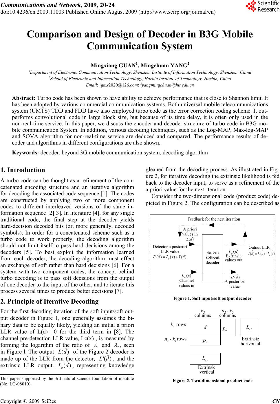 Communications and Network, 2009, 20-24 doi:10.4236/cn.2009.11003 Published Online August 2009 (http://www.scirp.org/journal/cn) Copyright © 2009 SciRes CN Comparison and Design of Decoder in B3G Mobile Communication System Mingxiang GUAN1, Mingchuan YANG2 1Department of Electronic Communication Technology, Shenzhen Institute of Information Technology, Shenzhen, China 2School of Electronic and Information Technology, Harbin Institute of Technology, Harbin, China Email: 1gmx2020@126.com; 2yangmingchuan@hit.edu.cn Abstract: Turbo code has been shown to have ability to achieve performance that is close to Shannon limit. It has been adopted by various commercial communication systems. Both universal mobile telecommunications system (UMTS) TDD and FDD have also employed turbo code as the error correction coding scheme. It out- performs convolutional code in large block size, but because of its time delay, it is often only used in the non-real-time service. In this paper, we discuss the encoder and decoder structure of turbo code in B3G mo- bile communication System. In addition, various decoding techniques, such as the Log-MAP, Max-log-MAP and SOVA algorithm for non-real-time service are deduced and compared. The performance results of de- coder and algorithms in different configurations are also shown. Keywords: decoder, beyond 3G mobile communication system, decoding algorithm 1. Introduction A turbo code can be thought as a refinement of the con- catenated encoding structure and an iterative algorithm for decoding the associated code sequence [1]. The codes are constructed by applying two or more component codes to different interleaved versions of the same in- formation sequence [2][3]. In literature [4], for any single traditional code, the final step at the decoder yields hard-decision decoded bits (or, more generally, decoded symbols). In order for a concatenated scheme such as a turbo code to work properly, the decoding algorithm should not limit itself to pass hard decisions among the decoders [5]. To best exploit the information learned from each decoder, the decoding algorithm must effect an exchange of soft rather than hard decisions [6]. For a system with two component codes, the concept behind turbo decoding is to pass soft decisions from the output of one decoder to the input of the other, and to iterate this process several times to produce better decisions [7]. 2. Principle of Iterative Decoding For the first decoding iteration of the soft input/soft out- put decoder in Figure 1, one generally assumes the bi- nary data to be equally likely, yielding an initial a priori LLR value of L(d) =0 for the third term in [8]. The channel pre-detection LLR value, Lc(x) , is measured by forming the logarithm of the ratio o1 f and 2 , seen in Figure l. The outputˆ) of the Figure 2 decoder is made up of the LLR from the detector, , and the extrinsic LLR output. , representing knowledge gleaned from the decoding process. As illustrated in Fig- ure 2, for iterative decoding the extrinsic likelihood is fed back to the decoder input, to serve as a refinement of the a priori value for the next iteration. Consider the two-dimensional code (product code) de- picted in Figure 2. The configuration can be described as Figure 1. Soft input/soft output decoder (Ld ˆ ( e Ld ˆ '( )Ld ) This paper supported by the 3rd natural science foundation of institute (No. LG-08010). Figure 2. Two-dimensional product code 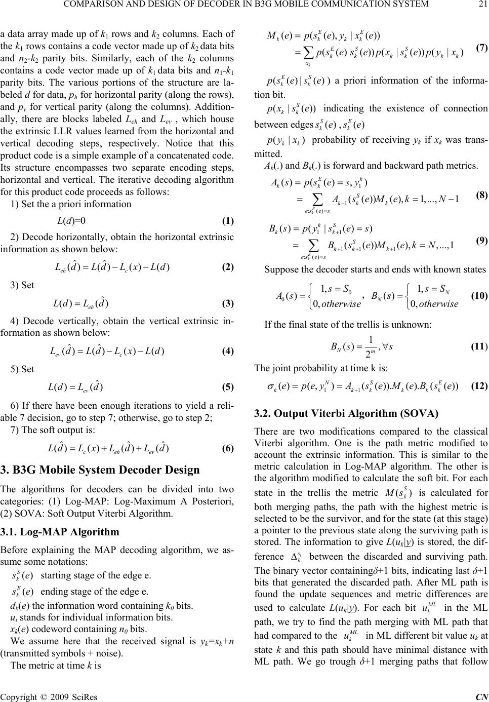 COMPARISON AND DESIGN OF DECODER IN B3G MOBILE COMMUNICATION SYSTEM 21 a data array made up of k1 rows and k2 columns. Each of the k1 rows contains a code vector made up of k2 data bits and n2-k2 parity bits. Similarly, each of the k 2 columns contains a code vector made up of k1 data bits and n1-k1 parity bits. The various portions of the structure are la- beled d for data, ph for horizontal parity (along the rows), and pv for vertical parity (along the columns). Addition- ally, there are blocks labeled Leh and L ev , which house the extrinsic LLR values learned from the horizontal and vertical decoding steps, respectively. Notice that this product code is a simple example of a concatenated code. Its structure encompasses two separate encoding steps, horizontal and vertical. The iterative decoding algorithm for this product code proceeds as follows: 1) Set the a priori information L(d)=0 (1) 2) Decode horizontally, obtain the horizontal extrinsic information as shown below: ˆˆ ()()() () eh c LdLdLx Ld (2) 3) Set ˆ () () eh LdL d (3) 4) Decode vertically, obtain the vertical extrinsic in- formation as shown below: ˆˆ ()()() () ev c LdLdLxLd (4) 5) Set ˆ ()() ev LdL d (5 ) 6) If there have been enough iterations to yield a reli- able 7 decision, go to step 7; otherwise, go to step 2; 7) The soft output is: ˆˆ () ()()() ceh ev LdL xLdLd ˆ (6) 3. B3G Mobile System Decoder Design The algorithms for decoders can be divided into two categories: (1) Log-MAP: Log-Maximum A Posteriori, (2) SOVA: Soft Output Viterbi Algorithm. 3.1. Log-MAP Algorithm Before explaining the MAP decoding algorithm, we as- sume some notations: () S k s e starting stage of the edge e. () E k s e ending stage of the edge e. dk(e) the information word containing k0 bits. ui stands for individual information bits. xk(e) codeword containing n0 bits. We assume here that the received signal is yk=xk+n (transmitted symbols + noise). The metric at time k is ()((),|()) (()|())(| ())(|) k EE kkkk ES S kk kkkk x Mepsey xe psesepxsepyx (7) (() E k pse |() S k s e) a priori information of the informa- tion bit. (|()) S kk pxs e k indicating the existence of connection between edges() S s e,() E k s e (|) kk pyx probability of receiving yk if xk was trans- mitted. Ak(.) and Bk(.) is forward and backward path metrics. 1 1 :() ()( (),) (( ))( ),1,...,1 E k Ek kk S kk k es e s Asps esy AseMek N (8) 11 11 1 :() ()(|()) (())( ),,...,1 E k kS kk S kk k es e s Bspy ses BseMekN (9) Suppose the decoder starts and ends with known states 0 0 1, 1, ()() 0, 0, N N sS sS AsB s otherwise otherwise , (10) If the final state of the trellis is unknown: 1 () , 2 Nm Bs s (11) The joint probability at time k is: 11 ()(,)( ()).(). (()) NS E kkkk epeyAseMeBse kk (12) 3.2. Output Viterbi Algorithm (SOVA) There are two modifications compared to the classical Viterbi algorithm. One is the path metric modified to account the extrinsic information. This is similar to the metric calculation in Log-MAP algorithm. The other is the algorithm modified to calculate the soft bit. For each state in the trellis the metric () S k M s is calculated for both merging paths, the path with the highest metric is selected to be the survivor, and for the state (at this stage) a pointer to the previous state along the surviving path is stored. The information to give L(uk|y) is stored, the dif- ference i s k between the discarded and surviving path. The binary vector containingδ+1 bits, indicating last δ+1 bits that generated the discarded path. After ML path is found the update sequences and metric differences are used to calculate L(uk|y). For each bit M L k u in the ML path, we try to find the path merging with ML path that had compared to the M L k u in ML different bit value uk at state k and this path should have minimal distance with ML path. We go trough δ+1 merging paths that follow C opyright © 2009 SciRes CN 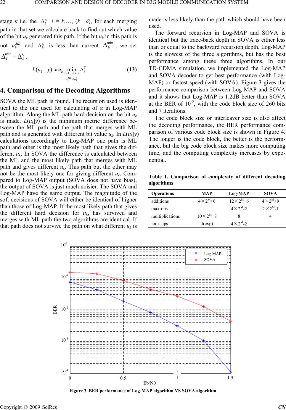 22 COMPARISON AND DESIGN OF DECODER IN B3G MOBILE COMMUNICATION SYSTEM Copyright © 2009 SciRes CN stage k i.e. the i s k i = k,…, (k +δ), for each merging path in that set we calculate back to find out which value of the bit uk generated this path. If the bit uk in this path is not M L k u and i s k is less than current , we set =. min k min k i s k ... (|y)min i ML i kk S kk i ik k uu u Lu ( 13) 4. Comparison of the Decoding Algorithms SOVA the ML path is found. The recursion used is iden- tical to the one used for calculating of α in Log-MAP algorithm. Along the ML path hard decision on the bit uk is made. L(uk|y) is the minimum metric difference be- tween the ML path and the path that merges with ML path and is generated with different bit value uk. In L(uk|y) calculations accordingly to Log-MAP one path is ML path and other is the most likely path that gives the dif- ferent uk. In SOVA the difference is calculated between the ML and the most likely path that merges with ML path and gives different uk. This path but the other may not be the most likely one for giving different uk. Com- pared to Log-MAP output (SOVA does not have bias), the output of SOVA is just much noisier. The SOVA and Log-MAP have the same output. The magnitude of the soft decisions of SOVA will either be identical of higher than those of Log-MAP. If the most likely path that gives the different hard decision for u k, has survived and merges with ML path the two algorithms are identical. If that path does not survive the path on what different uk is made is less likely than the path which should have been used. The forward recursion in Log-MAP and SOVA is identical but the trace-back depth in SOVA is either less than or equal to the backward recursion depth. Log-MAP is the slowest of the three algorithms, but has the best performance among these three algorithms. In our TD-CDMA simulation, we implemented the Log-MAP and SOVA decoder to get best performance (with Log- MAP) or fastest speed (with SOVA). Figure 3 gives the performance comparison between Log-MAP and SOVA and it shows that Log-MAP is 1.2dB better than SOVA at the BER of 10-2, with the code block size of 260 bits and 7 iterations. The code block size or interleaver size is also affect the decoding performance, the BER performance com- parison of various code block size is shown in Figure 4. The longer is the code block, the better is the perform- ance, but the big code block size makes more computing time, and the computing complexity increases by expo- nential. Table 1. Comparison of complexity of different decoding algorithms Operations MAP Log-MAP SOVA additions 4×2M+6 12×2M+6 4×2M+9 max-ops 4×2M-2 2×2M-1 multiplications 10×2M+8 8 4 look-ups 4(exp) 4×2M-2 Figure 3. BER performance of Log-MAP algorithm VS SOVA algorithm Log-MAP SOVA BER Eb/N0 1.5 1 0.5 10-4 0 10-3 10-2 10-1 100 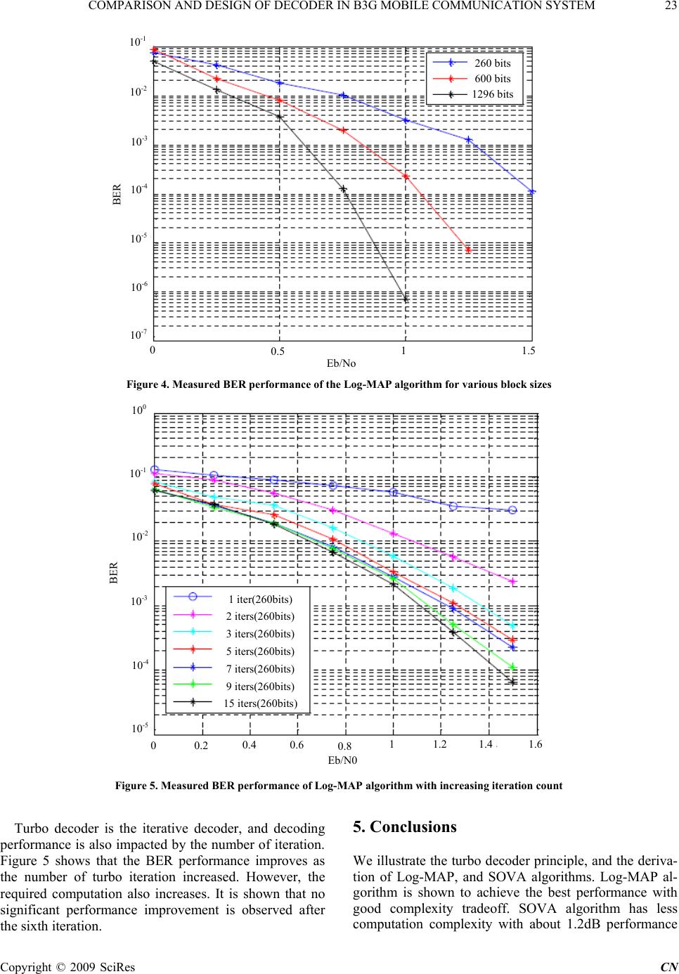 COMPARISON AND DESIGN OF DECODER IN B3G MOBILE COMMUNICATION SYSTEM 23 10-1 260 bits 600 bits 1296 bits 10-2 10-3 BER 10-4 10-5 10-6 10-7 0 1.5 1 0.5 Eb/No Figure 4. Measured BER performance of the Log-MAP algorithm for various block sizes 100 10-1 10-2 BER 1 iter(260bits) 2 iters(260bits) 3 iters(260bits) 5 iters(260bits) 7 iters(260bits) 10-3 10-4 9 iters(260bits) 15 iters ( 260bits ) 10-5 1.4 1.2 11.6 0.4 0.6 0.2 0 0.8 Eb/N0 Figure 5. Measured BER performance of Log-MAP algorithm with increasing iteration count Turbo decoder is the iterative decoder, and decoding performance is also impacted by the number of iteration. Figure 5 shows that the BER performance improves as the number of turbo iteration increased. However, the required computation also increases. It is shown that no significant performance improvement is observed after the sixth iteration. 5. Conclusions We illustrate the turbo decoder principle, and the deriva- tion of Log-MAP, and SOVA algorithms. Log-MAP al- gorithm is shown to achieve the best performance with good complexity tradeoff. SOVA algorithm has less computation complexity with about 1.2dB performance C opyright © 2009 SciRes CN  24 COMPARISON AND DESIGN OF DECODER IN B3G MOBILE COMMUNICATION SYSTEM degradation compared with Log-MAP at the BER of 10-2. We also demonstrate that the performance of turbo code is directly proportional to the interleaver size and number of iteration in the turbo decoder. Finally, it is also shown that the performance is affected by the scale of the input soft bits power but the effect is negligible when the scal- ing factor is larger than 0.8. 6. Acknowledgments The author would like to thank Dr. Li Lu to help to de- sign simulation platform, and Prof. Gu Xuemai for his revision of the text, and the editor and the anonymous reviewers for their contributions that enriched the final paper. REFERENCES [1] PIETROBON S S. Implementation and performance of a turbo/ MAP decoder. Int. J. Satellite Communication, 1998, 16: 23-46. [2] KAZA J, CHAKRABARTI C. Design and implementation of low-energy turbo decoders. IEEE Transactions on Very Large Scale Integration (VLSI) Systems, 2004, 12(9): 968-977. [3] HAGH M, SALEHI M, ET AL. Implementation issues in turbo decoding for 3GPP FDD receiver. Wireless Personal Communi- cations, 2006, 39(2): 165-182. [4] LEE D-S, PARK I.-C. Low-power log-MAP decoding based on reduced metric memory access. IEEE Transactions on Circuits and Systems, 2006, 53(6): 1244-1253. [5] BOUTILLON E, GROSS W J, GULAK P G. VLSI architectures for the MAP algorithm. IEEE Transactions on Communications, 2003, 51(2): 175-185. [6] ANANTHARAM V E Y. Iterative decoder architectures. IEEE Communications Magazine, 2003, 41(8): 132-140. [7] KWON T-W, CHOI J-R. Implementation of a two-step SOVA decoder with a fixed scaling factor. IEICE Transactions on Communications, E86-B(6): Jun. 2003, 1893-1900. [8] CHEN Y, PARHI K K. On the performance and imple- mentation issues of interleaved single parity check turbo product codes. Journal of VLSI Signal Processing Systems for Signal, Image, and Video Technology, 2005, 39(1): 35-47. Copyright © 2009 SciRes CN |