Paper Menu >>
Journal Menu >>
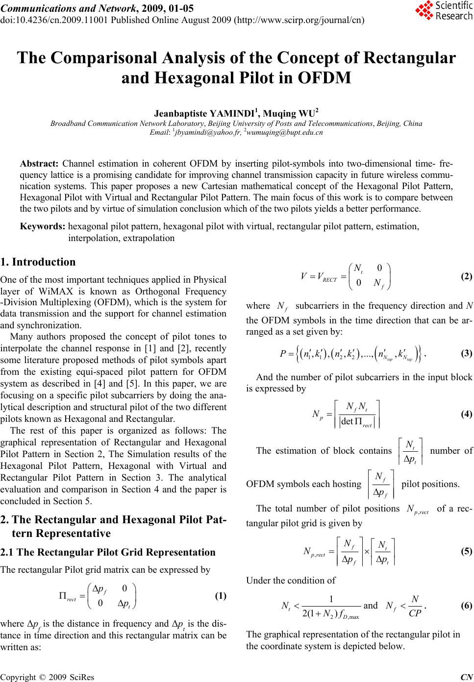 Communications and Network, 2009, 01-05 doi:10.4236/cn.2009.11001 Published Online August 2009 (http://www.scirp.org/journal/cn) Copyright © 2009 SciRes CN The Comparisonal Analysis of the Concept of Rectangular and Hexagonal Pilot in OFDM Jeanbaptiste YAMINDI1, Muqing WU2 Broadband Communication Network Laboratory, Beijing University of Posts and Telecommunications, Beijing, China Email: 1jbyamindi@yahoo.fr, 2wumuqing@bupt.edu.cn Abstract: Channel estimation in coherent OFDM by inserting pilot-symbols into two-dimensional time- fre- quency lattice is a promising candidate for improving channel transmission capacity in future wireless commu- nication systems. This paper proposes a new Cartesian mathematical concept of the Hexagonal Pilot Pattern, Hexagonal Pilot with Virtual and Rectangular Pilot Pattern. The main focus of this work is to compare between the two pilots and by virtue of simulation conclusion which of the two pilots yields a better performance. Keywords: hexagonal pilot pattern, hexagonal pilot with virtual, rectangular pilot pattern, estimation, interpolation, extrapolation 1. Introduction One of the most important techniques applied in Physical layer of WiMAX is known as Orthogonal Frequency -Division Multiplexing (OFDM), which is the system for data transmission and the support for channel estimation and synchronization. Many authors proposed the concept of pilot tones to interpolate the channel response in [1] and [2], recently some literature proposed methods of pilot symbols apart from the existing equi-spaced pilot pattern for OFDM system as described in [4] and [5]. In this paper, we are focusing on a specific pilot subcarriers by doing the ana- lytical description and structural pilot of the two different pilots known as Hexagonal and Rectangular. The rest of this paper is organized as follows: The graphical representation of Rectangular and Hexagonal Pilot Pattern in Section 2, The Simulation results of the Hexagonal Pilot Pattern, Hexagonal with Virtual and Rectangular Pilot Pattern in Section 3. The analytical evaluation and comparison in Section 4 and the paper is concluded in Section 5. 2. The Rectangular and Hexagonal Pilot Pat- tern Representative 2.1 The Rectangular Pilot Grid Representation The rectangular Pilot grid matrix can be expressed by 0 0 f rect t p p (1) where Δpf is the distance in frequency and Δpt is the dis- tance in time direction and this rectangular matrix can be written as: 0 0 t RECT f N VV N (2) where subcarriers in the frequency direction and N the OFDM symbols in the time direction that can be ar- ranged as a set given by: f N 112 2 , , ,,...,, tap tap NN Pnknknk . (3) And the number of pilot subcarriers in the input block is expressed by det ft p rect NN N (4 ) The estimation of block contains t t N p number of OFDM symbols each hosting f f N p pilot positions. The total number of pilot positions of a rec- tangular pilot grid is given by ,prect N , ft prect ft NN Npp (5) Under the condition of 2,max 1 2(1 ) t D NNf and f N NCP . (6) The graphical representation of the rectangular pilot in the coordinate system is depicted below.  2 THE COMPARISONAL ANALYSIS OF THE CONCEPT OF RECTANGULAR AND HEXAGONAL PILOT IN OFDM t Rec t an g ula r Figure 1. The rectangular pilot grid. 2.2 Modification of Rectangular Pilot Pattern The application of Cognitive Radio for optimum channel estimation by using pilot pattern can affect the frequency band by the presence of Licensed User. The pilot pattern in the presence of Licensed User can be classified ac- cording to the Bandwidth into Narrowband Licensed User and Wideband Licensed User. 1) The Narrowband Licensed User: It can exchange easily the position of the pilot symbols with data parts. This exchange of the pilot subcarrier is connected to the data subcarrier of the previous or the next subcarrier and we assumed that the application of pilot symbols in the channel estimation process cannot modify the pilot sym- bol but only one data subcarrier and can lose some throughput so this narrowband interference is depicted. 2) The Wideband Licensed: There are similarities in the process of Narrowband and Wideband, the only dif- ference is on the edge location of the License User signal exchange of two pilot subcarriers with data subcarriers and the number of deactivated subcarriers is depending upon the Licensed User Band. 2.3 The Hexagonal Pilot Grid Representation The implementation of Hexagonal Pilot is facilitated by the Virtual Pilot in reducing the Pilot Density by the annulment of u2 =0 and the Pilot Density becomes dp=| u1 v2| and the representation of the structure is according to the Hex- agonal Pilot spacing. The equation of the Hexagonal Pi- lot is expressed by t H ff NN VV NN (7) And graphically it can be represented as below. In both of the two different types of Pilot, the In- ter-Symbol Interference is still a big challenge during the process of pilot transmission. This challenge can be re- solved by the following techniques. Hexa g onal V2 V2 V1 V1 Figure 2. The hexagonal pilot grid. 2.4 Modification of Hexagonal Pilot Pattern The process of exchanging the position of the pilot sub- carrier with the data subcarrier connected to the previous subcarrier and the next subcarrier is done by exchanging the pilot subcarrier with the data subcarrier which lies in the previous subcarrier or in the next subcarrier. By do- ing this we can still be able to keep the pilot symbols to be used in the channel estimation process, but on the other side we will have to sacrifice one data subcarrier and thus lossing some throughput. This process is almost similar as in Rectangular process, the only difference, at the receiver, the received pilot symbols are processed using the iterative algorithm in order to obtain the virtual pilot symbol. This iterative algorithm introduces the concept of interpolation option which is applied via sim- ple averaging between the received shifted pilot symbols and the received pilot symbols. The received shifted pilot symbols in the next subcarrier or extrapolating the virtual pilot symbols on the position of the Licensed User by the effect of the received pilot symbols. 2.5 The Virtual Pilot The Virtual Pilot symbols are iterative of the interpola- tion of contiguous pilot to the position of the virtual. It is defined at first by the pilot spacing in frequency axis, which is smaller than the channel coherence bandwidth, and the second is pilot spacing in time axis, which is smaller than the channel coherence time on the initial computation of the received pilot symbols for each OFDM. The OFDM frames during each time slots, and subcarriers in the frequency domain respectively. Note that this operation must be processed only at the pilot positions as: , ,, , ˆ, kn kn kn kn N HH kn S (8) Sk,n is the transmitted symbol, the indexes k, and n in- dicates the position of each pilot symbol within the OFDM frame. The symbol W is the set of pilot positions within the OFDM sub frame. Copyright © 2009 SciRes CN 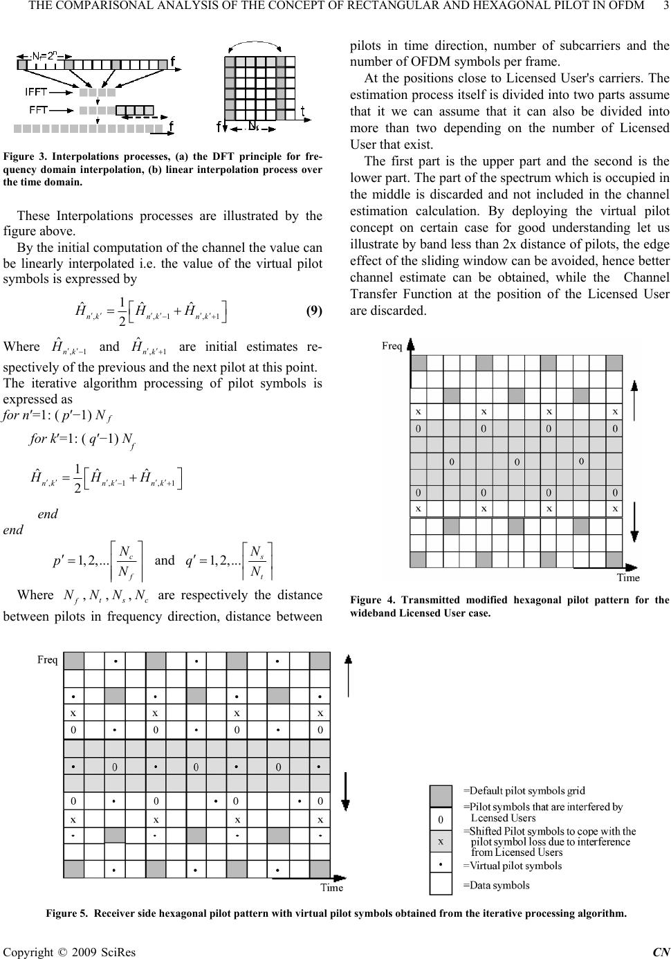 THE COMPARISONAL ANALYSIS OF THE CONCEPT OF RECTANGULAR AND HEXAGONAL PILOT IN OFDM 3 Copyright © 2009 SciRes CN pilots in time direction, number of subcarriers and the number of OFDM symbols per frame. At the positions close to Licensed User's carriers. The estimation process itself is divided into two parts assume that it we can assume that it can also be divided into more than two depending on the number of Licensed User that exist. Figure 3. Interpolations processes, (a) the DFT principle for fre- quency domain interpolation, (b) linear interpolation process over the time domain. The first part is the upper part and the second is the lower part. The part of the spectrum which is occupied in the middle is discarded and not included in the channel estimation calculation. By deploying the virtual pilot concept on certain case for good understanding let us illustrate by band less than 2x distance of pilots, the edge effect of the sliding window can be avoided, hence better channel estimate can be obtained, while the Channel Transfer Function at the position of the Licensed User are discarded. These Interpolations processes are illustrated by the figure above. By the initial computation of the channel the value can be linearly interpolated i.e. the value of the virtual pilot symbols is expressed by ,,1, 1 ˆˆˆ 2 nknk nk HHH 1 . (9) Where and 1 are initial estimates re- spectively of the previous and the next pilot at this point ,1 ˆnk H , ˆnk H The iterative algorithm processing of pilot symbols is expressed as for n′=1: ( p′−1) N f for k′=1: ( q′−1) Nf ,,1, 1 ˆˆˆ 2 nknk nk HHH 1 end end 1, 2,...c f N pN and 1,2, ... s t N qN Where , , f Nt N s N, are respectively the distance between pilots in frequency direction, distance between c NFigure 4. Transmitted modified hexagonal pilot pattern for the wideband Licensed User case. Figure 5. Receiver side hexagonal pilot pattern with virtual pilot symbols obtained from the iterative processing algorithm. 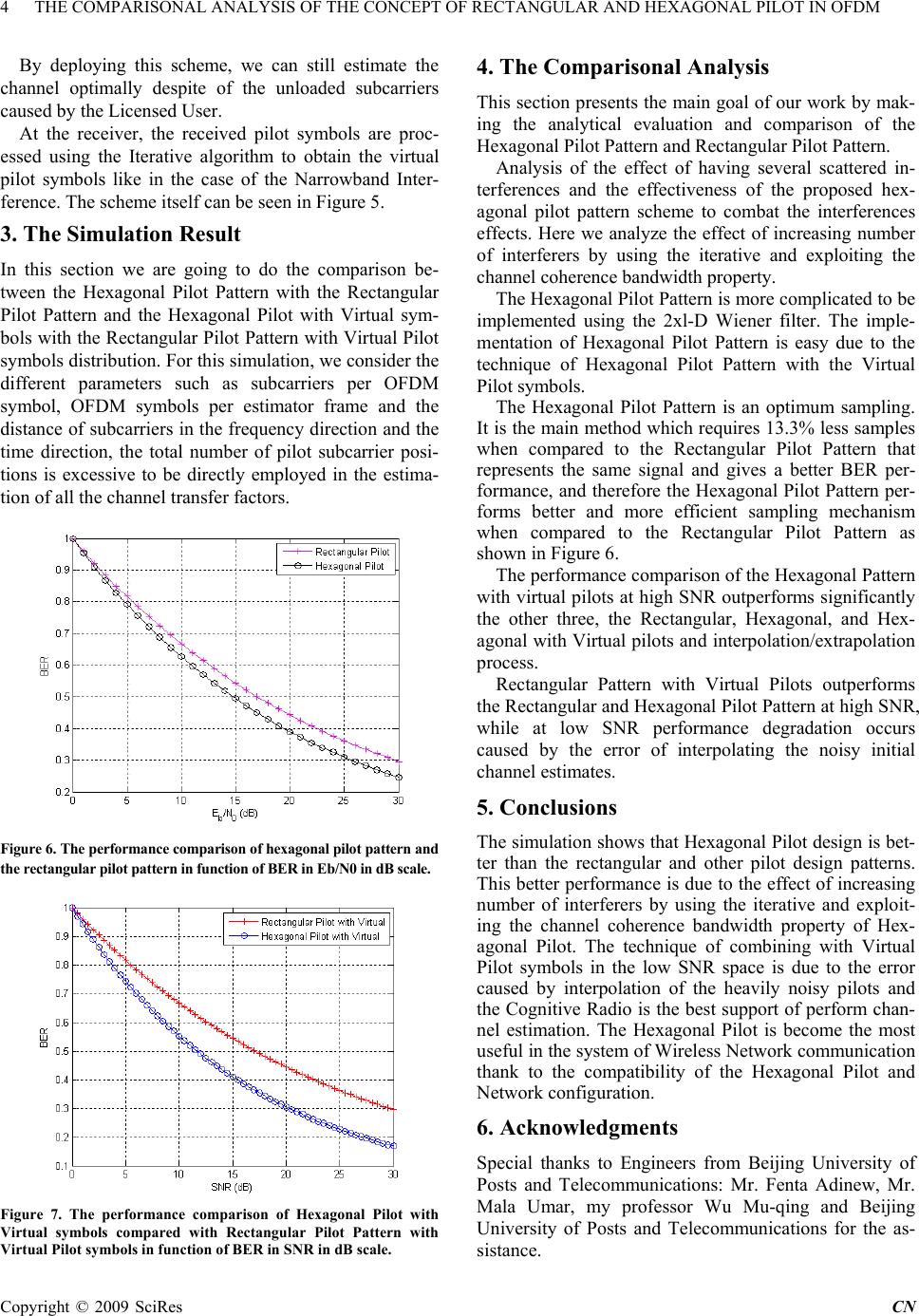 4 THE COMPARISONAL ANALYSIS OF THE CONCEPT OF RECTANGULAR AND HEXAGONAL PILOT IN OFDM By deploying this scheme, we can still estimate the channel optimally despite of the unloaded subcarriers caused by the Licensed User. At the receiver, the received pilot symbols are proc- essed using the Iterative algorithm to obtain the virtual pilot symbols like in the case of the Narrowband Inter- ference. The scheme itself can be seen in Figure 5. 3. The Simulation Result In this section we are going to do the comparison be- tween the Hexagonal Pilot Pattern with the Rectangular Pilot Pattern and the Hexagonal Pilot with Virtual sym- bols with the Rectangular Pilot Pattern with Virtual Pilot symbols distribution. For this simulation, we consider the different parameters such as subcarriers per OFDM symbol, OFDM symbols per estimator frame and the distance of subcarriers in the frequency direction and the time direction, the total number of pilot subcarrier posi- tions is excessive to be directly employed in the estima- tion of all the channel transfer factors. Figure 6. The performance comparison of hexagonal pilot pattern and the rectangular pilot pattern in function of BER in Eb/N0 in dB scale. Figure 7. The performance comparison of Hexagonal Pilot with Virtual symbols compared with Rectangular Pilot Pattern with Virtual Pilot symbols in function of BER in SNR in dB scale. 4. The Comparisonal Analysis This section presents the main goal of our work by mak- ing the analytical evaluation and comparison of the Hexagonal Pilot Pattern and Rectangular Pilot Pattern. Analysis of the effect of having several scattered in- terferences and the effectiveness of the proposed hex- agonal pilot pattern scheme to combat the interferences effects. Here we analyze the effect of increasing number of interferers by using the iterative and exploiting the channel coherence bandwidth property. The Hexagonal Pilot Pattern is more complicated to be implemented using the 2xl-D Wiener filter. The imple- mentation of Hexagonal Pilot Pattern is easy due to the technique of Hexagonal Pilot Pattern with the Virtual Pilot symbols. The Hexagonal Pilot Pattern is an optimum sampling. It is the main method which requires 13.3% less samples when compared to the Rectangular Pilot Pattern that represents the same signal and gives a better BER per- formance, and therefore the Hexagonal Pilot Pattern per- forms better and more efficient sampling mechanism when compared to the Rectangular Pilot Pattern as shown in Figure 6. The performance comparison of the Hexagonal Pattern with virtual pilots at high SNR outperforms significantly the other three, the Rectangular, Hexagonal, and Hex- agonal with Virtual pilots and interpolation/extrapolation process. Rectangular Pattern with Virtual Pilots outperforms the Rectangular and Hexagonal Pilot Pattern at high SNR, while at low SNR performance degradation occurs caused by the error of interpolating the noisy initial channel estimates. 5. Conclusions The simulation shows that Hexagonal Pilot design is bet- ter than the rectangular and other pilot design patterns. This better performance is due to the effect of increasing number of interferers by using the iterative and exploit- ing the channel coherence bandwidth property of Hex- agonal Pilot. The technique of combining with Virtual Pilot symbols in the low SNR space is due to the error caused by interpolation of the heavily noisy pilots and the Cognitive Radio is the best support of perform chan- nel estimation. The Hexagonal Pilot is become the most useful in the system of Wireless Network communication thank to the compatibility of the Hexagonal Pilot and Network configuration. 6. Acknowledgments Special thanks to Engineers from Beijing University of Posts and Telecommunications: Mr. Fenta Adinew, Mr. Mala Umar, my professor Wu Mu-qing and Beijing University of Posts and Telecommunications for the as- sistance. Copyright © 2009 SciRes CN  THE COMPARISONAL ANALYSIS OF THE CONCEPT OF RECTANGULAR AND HEXAGONAL PILOT IN OFDM 5 REFERENCES [1] YIN Q Y, ZHANG Y, DING L. A new space diversity technology. Transaction of Xi’ an Jiaotong University. 2005, 39(6): 551-557. [2] SENDONARIS A, ERKIP E, AAZHANG B. Increasing uplink capacity via user cooperation diversity. IEEE Int. Symp. on Information Theory, Cambridge, MA, Aug. 1998, 156. [3] HASNA M O, ALOUINI M S. Harmonic mean and end-to-end performance of transmission systems with relays. IEEE Transactions on Communications, January 2004, 52(1). [4] HASNA M O, ALOUINI M S. Performance analysis of two-hop relayed transmission over Rayleigh fading channels. In Proc. IEEE Vehicular Technology Conf. (VTC’02), Vancouver, BC, Canada, Sept. 2002, 1992-1996. [5] GRADSHTEYN I S, RYZHIK I M. Table of Integrals, Series, and Products.San Diego, CA: Academic Press, fifth ed., 1994. [6] ABRAMOWITZ M, STEGUN I A. Handbook of mathematical functions with formulas, graphs, and mathematical tables. NY: Dover Publications, New York, 9th Edition, 1970. [7] IKKI S, AHMED M H, Performance analysis of cooperative diversity wireless networks over nakagamim fading channel. IEEE Communications Letters, April 2007, 11(4). [8] SIMON M K, ALOUINI M S. Digital communication over fading channels: A unified approach to performance analysis. NEW York: Wiley, 2000. C opyright © 2009 SciRes CN |