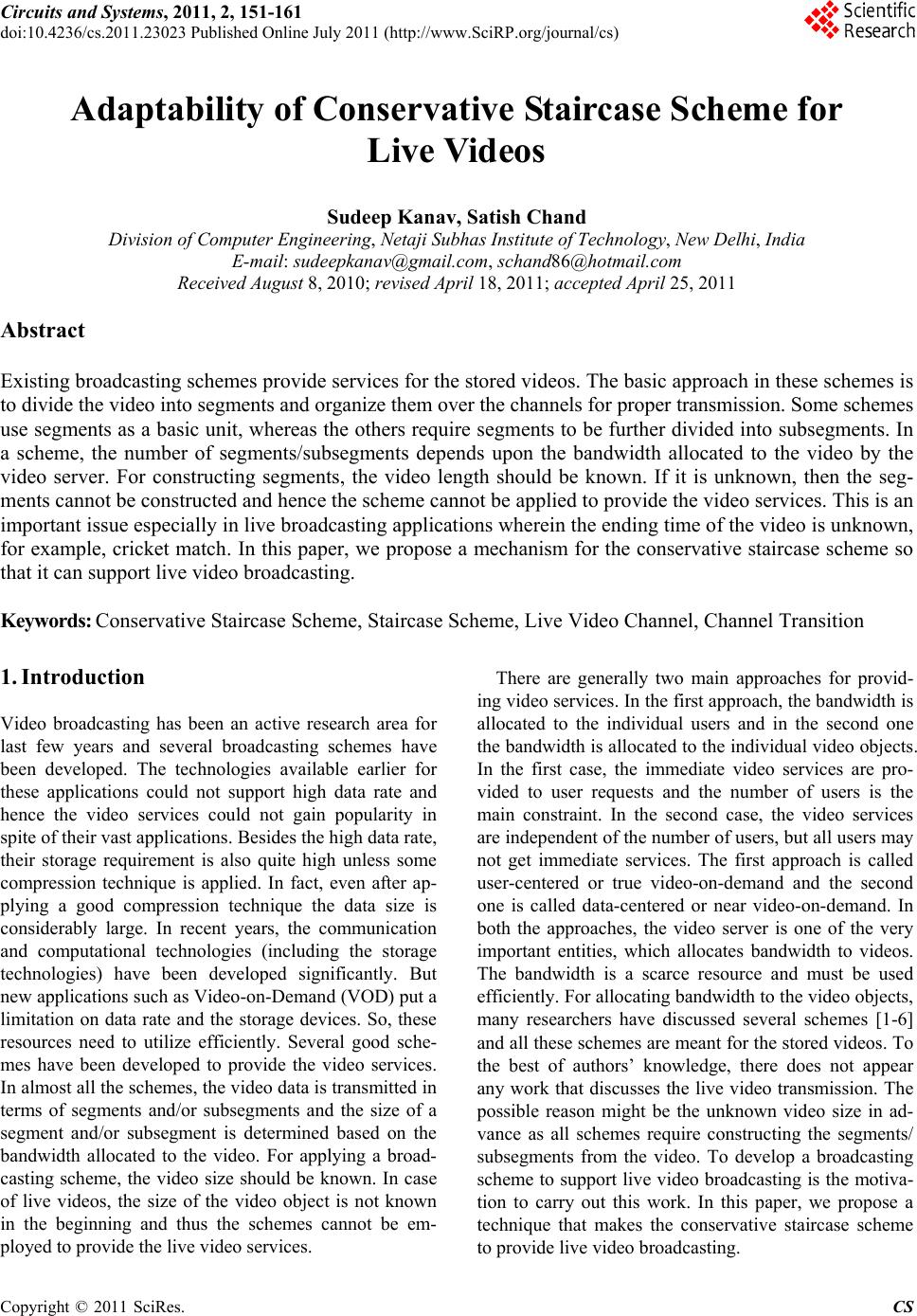
 Circuits and Systems, 2011, 2, 151-161 doi:10.4236/cs.2011.23023 Published Online July 2011 (http://www.SciRP.org/journal/cs) Copyright © 2011 SciRes. CS Adaptability of Conservative Staircase Scheme for Live Vi deos Sudeep Kanav, Satish Chand Division of Computer Engineering, Netaji Subhas Institute of Technology, New Delhi, India E-mail: sudeepkanav@gmail.com, schand86@hotmail.com Received August 8, 2010; revised April 18, 2011; accepted April 25, 2011 Abstract Existing broadcasting schemes provide services for the stored videos. The basic approach in these schemes is to divide the video into segments and organize them over the channels for proper transmission. Some schemes use segments as a basic unit, whereas the others require segments to be further divided into subsegments. In a scheme, the number of segments/subsegments depends upon the bandwidth allocated to the video by the video server. For constructing segments, the video length should be known. If it is unknown, then the seg- ments cannot be constructed and hence the scheme cannot be applied to provide the video services. This is an important issue especially in live broadcasting applications wherein the ending time of the video is unknown, for example, cricket match. In this paper, we propose a mechanism for the conservative staircase scheme so that it can support live video broadcasting. Keywords: Conservative Staircase Scheme, Staircase Scheme, Live Video Channel, Channel Transition 1. Introduction Video broadcasting has been an active research area for last few years and several broadcasting schemes have been developed. The technologies available earlier for these applications could not support high data rate and hence the video services could not gain popularity in spite of their vast applications. Besides the high data rate, their storage requirement is also quite high unless some compression technique is applied. In fact, even after ap- plying a good compression technique the data size is considerably large. In recent years, the communication and computational technologies (including the storage technologies) have been developed significantly. But new applications such as Video-on-Demand (VOD) put a limitation on data rate and the storage devices. So, these resources need to utilize efficiently. Several good sche- mes have been developed to provide the video services. In almost all the schemes, the video data is transmitted in terms of segments and/or subsegments and the size of a segment and/or subsegment is determined based on the bandwidth allocated to the video. For applying a broad- casting scheme, the video size should be known. In case of live videos, the size of the video object is not known in the beginning and thus the schemes cannot be em- ployed to provide the live video services. There are generally two main approaches for provid- ing video services. In the first approach, the bandwidth is allocated to the individual users and in the second one the bandwidth is allocated to the individual video objects. In the first case, the immediate video services are pro- vided to user requests and the number of users is the main constraint. In the second case, the video services are independent of the number of users, but all users may not get immediate services. The first approach is called user-centered or true video-on-demand and the second one is called data-centered or near video-on-demand. In both the approaches, the video server is one of the very important entities, which allocates bandwidth to videos. The bandwidth is a scarce resource and must be used efficiently. For allocating bandwidth to the video objects, many researchers have discussed several schemes [1-6] and all these schemes are meant for the stored videos. To the best of authors’ knowledge, there does not appear any work that discusses the live video transmission. The possible reason might be the unknown video size in ad- vance as all schemes require constructing the segments/ subsegments from the video. To develop a broadcasting scheme to support live video broadcasting is the motiva- tion to carry out this work. In this paper, we propose a technique that makes the conservative staircase scheme to provide live video broadcasting. 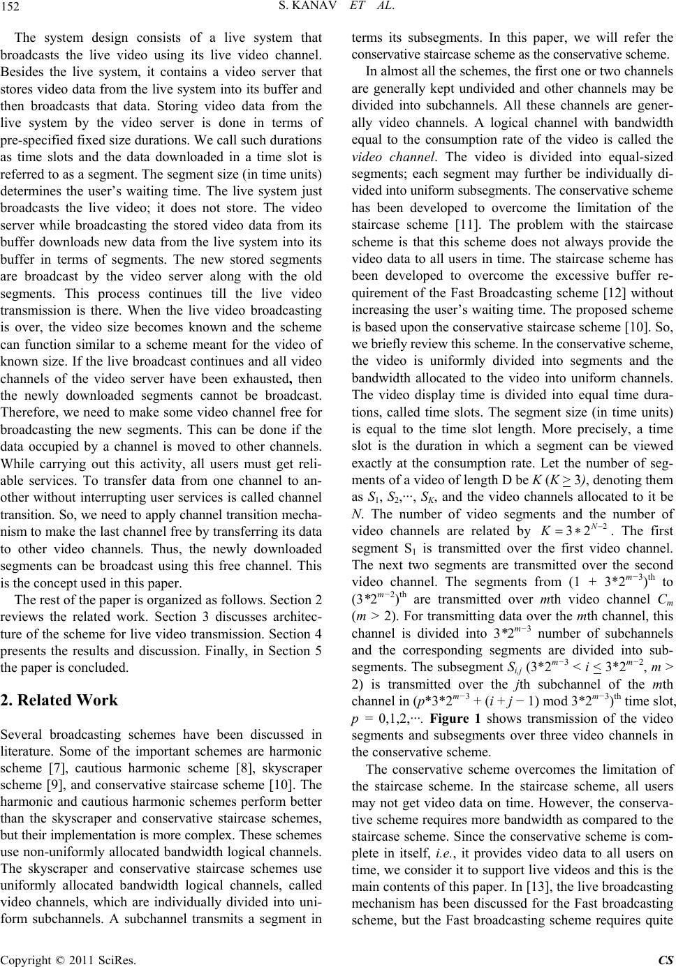 152 S. KANAV ET AL. The system design consists of a live system that broadcasts the live video using its live video channel. Besides the live system, it contains a video server that stores video data from the live system into its buffer and then broadcasts that data. Storing video data from the live system by the video server is done in terms of pre-specified fixed size durations. We call such durations as time slots and the data downloaded in a time slot is referred to as a segment. The segment size (in time units) determines the user’s waiting time. The live system just broadcasts the live video; it does not store. The video server while broadcasting the stored video data from its buffer downloads new data from the live system into its buffer in terms of segments. The new stored segments are broadcast by the video server along with the old segments. This process continues till the live video transmission is there. When the live video broadcasting is over, the video size becomes known and the scheme can function similar to a scheme meant for the video of known size. If the live broadcast continues and all video channels of the video server have been exhausted, then the newly downloaded segments cannot be broadcast. Therefore, we need to make some video channel free for broadcasting the new segments. This can be done if the data occupied by a channel is moved to other channels. While carrying out this activity, all users must get reli- able services. To transfer data from one channel to an- other without interrupting user services is called channel transition. So, we need to apply channel transition mecha- nism to make the last channel free by transferring its data to other video channels. Thus, the newly downloaded segments can be broadcast using this free channel. This is the concept used in this paper. The rest of the paper is organized as follows. Section 2 reviews the related work. Section 3 discusses architec- ture of the scheme for live video transmission. Section 4 presents the results and discussion. Finally, in Section 5 the paper is concluded. 2. Related Work Several broadcasting schemes have been discussed in literature. Some of the important schemes are harmonic scheme [7], cautious harmonic scheme [8], skyscraper scheme [9], and conservative staircase scheme [10]. The harmonic and cautious harmonic schemes perform better than the skyscraper and conservative staircase schemes, but their implementation is more complex. These schemes use non-uniformly allocated bandwidth logical channels. The skyscraper and conservative staircase schemes use uniformly allocated bandwidth logical channels, called video channels, which are individually divided into uni- form subchannels. A subchannel transmits a segment in terms its subsegments. In this paper, we will refer the conservative staircase scheme as the conservative scheme. In almost all the schemes, the first one or two channels are generally kept undivided and other channels may be divided into subchannels. All these channels are gener- ally video channels. A logical channel with bandwidth equal to the consumption rate of the video is called the video channel. The video is divided into equal-sized segments; each segment may further be individually di- vided into uniform subsegments. The conservative scheme has been developed to overcome the limitation of the staircase scheme [11]. The problem with the staircase scheme is that this scheme does not always provide the video data to all users in time. The staircase scheme has been developed to overcome the excessive buffer re- quirement of the Fast Broadcasting scheme [12] without increasing the user’s waiting time. The proposed scheme is based upon the conservative staircase scheme [10]. So, we briefly review this scheme. In the conservative scheme, the video is uniformly divided into segments and the bandwidth allocated to the video into uniform channels. The video display time is divided into equal time dura- tions, called time slots. The segment size (in time units) is equal to the time slot length. More precisely, a time slot is the duration in which a segment can be viewed exactly at the consumption rate. Let the number of seg- ments of a video of length D be K (K > 3), denoting them as S1, S2,···, SK, and the video channels allocated to it be N. The number of video segments and the number of video channels are related by . The first segment S1 is transmitted over the first video channel. The next two segments are transmitted over the second video channel. The segments from (1 + 3*2m−3)th to (3*2m−2)th are transmitted over mth video channel Cm 2 32 N K (m > 2). For transmitting data over the mth channel, this channel is divided into 3*2m−3 number of subchannels and the corresponding segments are divided into sub- segments. The subsegment Si,j (3*2m−3 < i < 3*2m−2, m > 2) is transmitted over the jth subchannel of the mth channel in (p*3*2m−3 + (i + j − 1) mod 3*2m−3)th time slot, p = 0,1,2,···. Figure 1 shows transmission of the video segments and subsegments over three video channels in the conservative scheme. The conservative scheme overcomes the limitation of the staircase scheme. In the staircase scheme, all users may not get video data on time. However, the conserva- tive scheme requires more bandwidth as compared to the staircase scheme. Since the conservative scheme is com- plete in itself, i.e., it provides video data to all users on time, we consider it to support live videos and this is the main contents of this paper. In [13], the live broadcasting mechanism has been discussed for the Fast broadcasting scheme, but the Fast broadcasting scheme requires quite Copyright © 2011 SciRes. CS  S. KANAV ET AL. Copyright © 2011 SciRes. CS 153 Time slots T 1 T 2 T 3 T 4 T 5 T 6 T 7 T 8 T 9 T 10 T 11 T 12 T 13 T 14 T 15 T 16 T 17 T 18 T 19 T 20 S 1 3 2 3 2 S 1 S 1 S 1 S 1 S 3 S 2 S 3 2 S 1 S 1 S 1 S 1 3 2 3 2 S 1 S 1 S 1 S 1 3 2 3 2 S 1 S 1 S 1 S 1 3 2 3 S 2 S 1 S 1 S 1 S 4,1 S 5,3 S 6,2 S 4,2 S 5,1 S 6,3 S 4,3 S 5,2 S 6,1 S 4,1 S 5,3 S 6,2 S 4,2 S 5,1 S 6,3 S 4,3 S 5,2 S 6,1 S 4,1 S 5,3 S 6,2 S 4,2 S 5,1 S 6,3 S 4,3 S 5,2 S 6,1 S 4,1 S 5,3 S 6,2 S 4,2 S 5,1 S 6,3 S 4,3 S 5,2 S 6,1 S 4,1 S 5,3 S 6,2 S 4,2 S 5,1 S 6,3 S 4,3 S 5,2 S 6,1 S 4,1 S 5,3 S 6,2 S 4,2 S 5,1 S 6,3 S 4,3 S 5,2 S 6,1 S 4,1 S 5,3 S 6,2 S 4,2 S 5,1 S 6,3 Figure 1. Transmission of segments/subsegments in conservative scheme. large amount of storage. That is why we consider the conservative staircase scheme for live broadcasting. In next section, we discuss the proposed scheme. 3. Adaptability of Conservative Scheme for Live Videos The conservative scheme needs the video size in the be- ginning to partition it into equal-sized segments and subsegments. Generally, in a live video we do not know the video size; so this scheme cannot be applied in its existing form. We modify its basic architecture. We do not divide the segments or video channels any further. For the modified conservative scheme, we discuss a me- chanism so that this scheme can support live video broadcasting. We assume that the bandwidth allocated to the video is finite. This assumption is not illogical be- cause for abundant bandwidth there is hardly any issue to discuss. In the proposed architecture, we have a live system that broadcasts the live video using its video channel, called the live channel. This live system is active while there is a live video and provides video services only once using its live video channel. There is one more sys- tem that stores the video data from the live system into its buffer. This system, called video server, broadcasts the stored video data. The live system broadcasts the video data at the consumption rate. The user requests received till the live system begins to broadcast the video data get all data from the live system directly. These re- quests require no buffer storage. The live video display is divided into fixed time durations, called time slots. The video server stores the video data from the live channel. The data downloaded and stored in a time slot constitutes a video segment. The segment size (in time units) deter- mines the user’s waiting time. After storing new segment in its buffer, the video server broadcasts that segment over its video channels and concurrently downloads new segments from the live system into its buffer. A request received after the live system has started the live video gets the missing initial data from the video server and the future data from the live channel. We now discuss the data transmission method used by the video server. a) Data Transmission Method All video segments Si (i = 1,2,···,K) are of uniform size (in time units) and they are constructed as discussed above. The video server broadcasts the segments as fol- lows: 1) The first channel C1 broadcasts the first segment S1, repeatedly. 2) The second channel C2 transmits next two segments S2 and S3, alternately and repeatedly. 3) The ith channel Ci (i > 2) broadcasts 3*2i−3 number of segments from (3*2i−3 + 1) to (3*2i−2), sequentially and periodically. Let the video server allocate N video channels C1, C2,···,CN to the desired video. After downloading the first segment S1, the video server broadcasts this segment over its first video channel C1, repeatedly, and concur- rently downloads the second segment S2 into its buffer from the live system. After the video server stores the segment S2 into buffer from the live system, it broadcasts S2 from the next time slot along with S1 according to the data transmission Method. When the video server bro- adcasts S1 and S2, it stores third segment S3 from the live system into its buffer and then broadcasts S3 along with S1 and S2. A user request is allowed to get video data from the live system or the video server at the starting point of a time slot, not in between; thus, a user may have to wait for at most one time slot. If a user request is received when the live system broadcasts S1, it would get the data from the live system at the start of the second time slot, but by that time this request must has missed S1. The segment S1 has already been stored by the video server in its buffer in the first time slot and in the next time slot, i.e., second time slot, it is broadcast by the 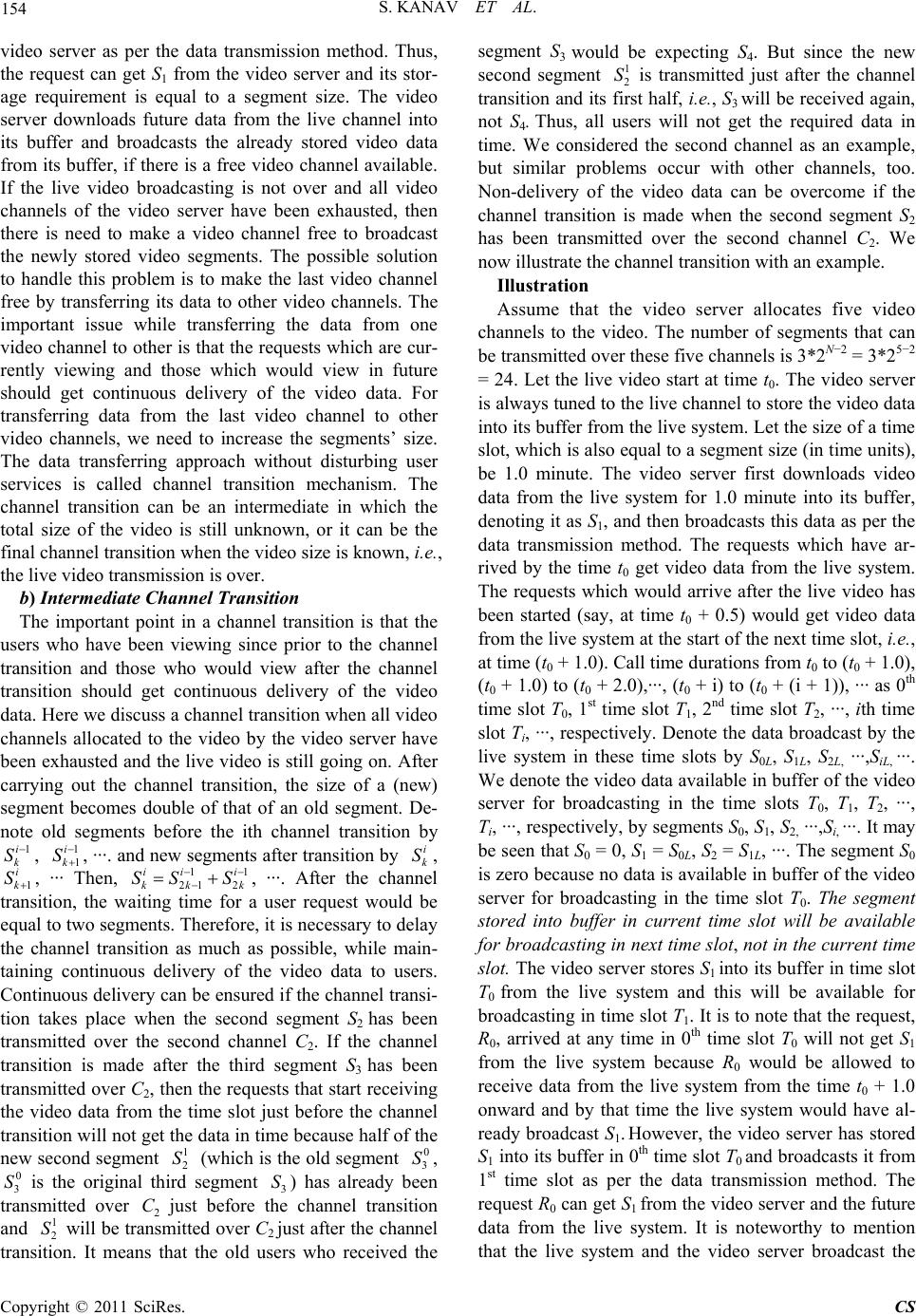 154 1 S. KANAV ET AL. video server as per the data transmission method. Thus, the request can get S1 from the video server and its stor- age requirement is equal to a segment size. The video server downloads future data from the live channel into its buffer and broadcasts the already stored video data from its buffer, if there is a free video channel available. If the live video broadcasting is not over and all video channels of the video server have been exhausted, then there is need to make a video channel free to broadcast the newly stored video segments. The possible solution to handle this problem is to make the last video channel free by transferring its data to other video channels. The important issue while transferring the data from one video channel to other is that the requests which are cur- rently viewing and those which would view in future should get continuous delivery of the video data. For transferring data from the last video channel to other video channels, we need to increase the segments’ size. The data transferring approach without disturbing user services is called channel transition mechanism. The channel transition can be an intermediate in which the total size of the video is still unknown, or it can be the final channel transition when the video size is known, i.e., the live video transmission is over. b) Intermediate Channel Transition The important point in a channel transition is that the users who have been viewing since prior to the channel transition and those who would view after the channel transition should get continuous delivery of the video data. Here we discuss a channel transition when all video channels allocated to the video by the video server have been exhausted and the live video is still going on. After carrying out the channel transition, the size of a (new) segment becomes double of that of an old segment. De- note old segments before the ith channel transition by , , ···. and new segments after transition by , 1, ··· Then, k , ···. After the channel transition, the waiting time for a user request would be equal to two segments. Therefore, it is necessary to delay the channel transition as much as possible, while main- taining continuous delivery of the video data to users. Continuous delivery can be ensured if the channel transi- tion takes place when the second segment S2 has been transmitted over the second channel C2. If the channel transition is made after the third segment S3 has been transmitted over C2, then the requests that start receiving the video data from the time slot just before the channel transition will not get the data in time because half of the new second segment (which is the old segment , is the original third segment 3) has already been transmitted over 2 just before the channel transition and will be transmitted over C2 just after the channel transition. It means that the old users who received the segment S3 would be expecting S4. But since the new second segment is transmitted just after the channel transition and its first half, i.e., S3 will be received again, not S4. Thus, all users will not get the required data in time. We considered the second channel as an example, but similar problems occur with other channels, too. Non-delivery of the video data can be overcome if the channel transition is made when the second segment S2 has been transmitted over the second channel C2. We now illustrate the channel transition with an example. 1i k S i k S 0 3 S 1 1 i k S 1 2 S i k S 0 3 S 1 21 2 ii i kk SS S 1 2 S C S 1 2 S Illustration Assume that the video server allocates five video channels to the video. The number of segments that can be transmitted over these five channels is 3*2N−2 = 3*25−2 = 24. Let the live video start at time t0. The video server is always tuned to the live channel to store the video data into its buffer from the live system. Let the size of a time slot, which is also equal to a segment size (in time units), be 1.0 minute. The video server first downloads video data from the live system for 1.0 minute into its buffer, denoting it as S1, and then broadcasts this data as per the data transmission method. The requests which have ar- rived by the time t0 get video data from the live system. The requests which would arrive after the live video has been started (say, at time t0 + 0.5) would get video data from the live system at the start of the next time slot, i.e., at time (t0 + 1.0). Call time durations from t0 to (t0 + 1.0), (t0 + 1.0) to (t0 + 2.0),···, (t0 + i) to (t0 + (i + 1)), ··· as 0th time slot T0, 1st time slot T1, 2nd time slot T2, ···, ith time slot Ti, ···, respectively. Denote the data broadcast by the live system in these time slots by S0L, S1L, S2L, ···,SiL, ···. We denote the video data available in buffer of the video server for broadcasting in the time slots T0, T1, T2, ···, Ti, ···, respectively, by segments S0, S1, S2, ···,Si, ···. It may be seen that S0 = 0, S1 = S0L, S2 = S1L, ···. The segment S0 is zero because no data is available in buffer of the video server for broadcasting in the time slot T0. The segment stored into buffer in current time slot will be available for broadcasting in next time slot, not in the current time slot. The video server stores S1 into its buffer in time slot T0 from the live system and this will be available for broadcasting in time slot T1. It is to note that the request, R0, arrived at any time in 0th time slot T0 will not get S1 from the live system because R0 would be allowed to receive data from the live system from the time t0 + 1.0 onward and by that time the live system would have al- ready broadcast S1. However, the video server has stored S1 into its buffer in 0th time slot T0 and broadcasts it from 1st time slot as per the data transmission method. The request R0 can get S1 from the video server and the future data from the live system. It is noteworthy to mention that the live system and the video server broadcast the Copyright © 2011 SciRes. CS 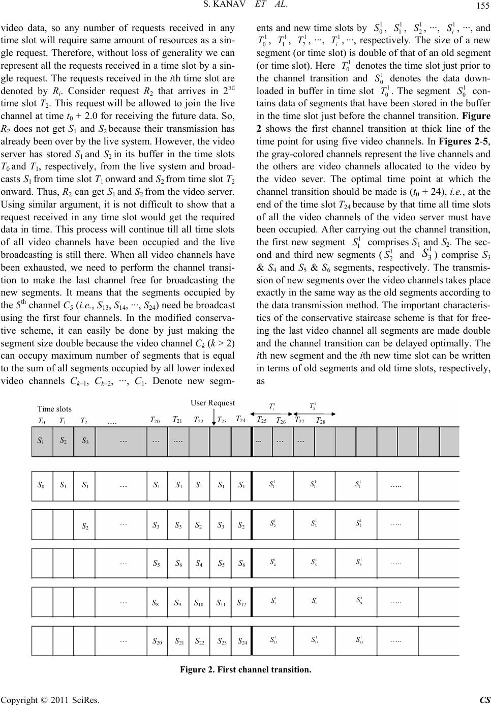 S. KANAV ET AL. Copyright © 2011 SciRes. CS 155 ents and new time slots by , , , ···, , ···, and , , , ···, , ···, respectively. The size of a new segment (or time slot) is double of that of an old segment (or time slot). Here denotes the time slot just prior to the channel transition and denotes the data down- loaded in buffer in time slot . The segment con- tains data of segments that have been stored in the buffer in the time slot just before the channel transition. Figure 2 shows the first channel transition at thick line of the time point for using five video channels. In Figures 2-5, the gray-colored channels represent the live channels and the others are video channels allocated to the video by the video sever. The optimal time point at which the channel transition should be made is (t0 + 24), i.e., at the end of the time slot T24 because by that time all time slots of all the video channels of the video server must have been occupied. After carrying out the channel transition, the first new segment comprises S1 and S2. The sec- ond and third new segments ( and ) comprise S3 & S4 and S5 & S6 segments, respectively. The transmis- sion of new segments over the video channels takes place exactly in the same way as the old segments according to the data transmission method. The important characteris- tics of the conservative staircase scheme is that for free- ing the last video channel all segments are made double and the channel transition can be delayed optimally. The ith new segment and the ith new time slot can be written in terms of old segments and old time slots, respectively, s 1 0 S 1 0 S 0 T S 1 1 S 1 2 1 2 S S 1 i S S 1 0 T1 1 T1 2 T1 i T T1 0 S 1 1 0 1 11 3 video data, so any number of requests received in any time slot will require same amount of resources as a sin- gle request. Therefore, without loss of generality we can represent all the requests received in a time slot by a sin- gle request. The requests received in the ith time slot are denoted by Ri. Consider request R2 that arrives in 2nd time slot T2. This request will be allowed to join the live channel at time t0 + 2.0 for receiving the future data. So, R2 does not get S1 and S2 because their transmission has already been over by the live system. However, the video server has stored S1 and S2 in its buffer in the time slots T0 and T1, respectively, from the live system and broad- casts S1 from time slot T1 onward and S2 from time slot T2 onward. Thus, R2 can get S1 and S2 from the video server. Using similar argument, it is not difficult to show that a request received in any time slot would get the required data in time. This process will continue till all time slots of all video channels have been occupied and the live broadcasting is still there. When all video channels have been exhausted, we need to perform the channel transi- tion to make the last channel free for broadcasting the new segments. It means that the segments occupied by the 5th channel C5 (i.e., S13, S14, ···, S24) need be broadcast using the first four channels. In the modified conserva- tive scheme, it can easily be done by just making the segment size double because the video channel Ck (k > 2) can occupy maximum number of segments that is equal to the sum of all segments occupied by all lower indexed video channels Ck–1, Ck–2, ···, C1. Denote new segm- a Time slots S 1 S 2 S 3 S 0 S 1 S 1 T 0 T 1 S 2 T 2 20 T 21 22 23 T 24 25 26 T 27 28 User Reques 1 1 T1 2 T 1 1 S1 1 S1 1 S 1 2 S1 3 S1 2 S 1 4 S1 5 S1 6 S 1 7 S1 8 S1 9 S 1 13 S1 14 S1 15 S S 1 S 1 S 1 S 1 S 1 S 3 S 3 S 2 S 3 S 2 S 5 S 6 S 4 S 5 S 6 S 8 S 9 S 10 S 11 S 12 S 20 S 21 S 22 S 23 S 24 Figure 2. First channel transition. 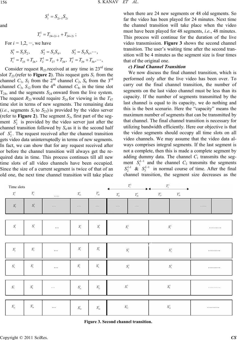 S. KANAV ET AL. Copyright © 2011 SciRes. CS 156 i i ,, ,, 1 212ii SSS and 1 24 2124 2ii TT T ; For i = 1,2, ···, we have 11 1 112 234 356 111 1252622728 32930 ,, ,, SSS SSS SSS TT TTTTTTT Consider request R23 received at any time in 23rd time slot T23 (refer to Figure 2). This request gets S1 from the channel C1, S2 from the 2nd channel C 2, S6 from the 3rd channel C3, S12 from the 4th channel C4, in the time slot T24, and the segments S24 onward from the live system. The request R23 would require S24 for viewing in the T47 time slot in terms of new segments. The remaining data (i.e., segments S1 to S23) is provided by the video server (refer to Figure 2). The segment S3, first part of the seg- ment is provided by the video server just after the channel transition followed by S4 as it is the second half of . The request received after the channel transition gets video data uninterruptedly in terms of new segments. In fact, we can show that for any request received after or before the channel transition will always get the re- quired data in time. This process continues till all new time slots of all video channels have been occupied. Since the size of a current segment is twice of that of an old one, the next time channel transition will take place 1 2 S 1 2 S when there are 24 new segments or 48 old segments. So far the video has been played for 24 minutes. Next time the channel transition will take place when the video must have been played for 48 segments, i.e., 48 minutes. This process will continue for the duration of the live video transmission. Figure 3 shows the second channel transition. The user’s waiting time after the second tran- sition will be 4 minutes as the segment size is four times that of the original one. c) Final Channel Transition We now discuss the final channel transition, which is performed only after the live video has been over. To carry out the final channel transition, the number of segments on the last video channel must be less than its capacity. If the number of segments transmitted by the last channel is equal to its capacity, we do nothing and this is the best scenario. Here the “capacity” means the maximum number of segments that can be transmitted by that channel. The final channel transition is necessary for utilizing bandwidth efficiently. Here our objective is that the video segments should occupy all time slots on all video channels. We may assume that the video data al- ways comprises integral segments. If the last segment is not a complete, then this is made a complete segment by adding dummy data. The channel C1 transmits the seg- ment 1 1 S and the channel C2 transmits the segments -1 2 S & 1 3 S in normal course of time. After the final channel transition, the segment size decreases as the Time slots 1 1 T 1 2 S 1 3 S 1 2 T 1 1 S 1 1 S 1 2 S 1 3 S 1 4 S 1 5 S 1 7 S 1 8 S 1 13 S 1 14 S 1 23 S 1 24 S 1 11 S 1 12 S 1 5 S 1 6 S 1 3 S 1 2 S 1 1 S1 1 S 1 23 T 1 24 T1 25 T1 26 T1 27 T1 28 T 2 1 T2 2 T 2 1 S2 1 S 2 2 S2 3 S 2 4 S2 5 S 2 7 S2 8 S 2 13 S2 14 S Figure 3. Second channel transition. 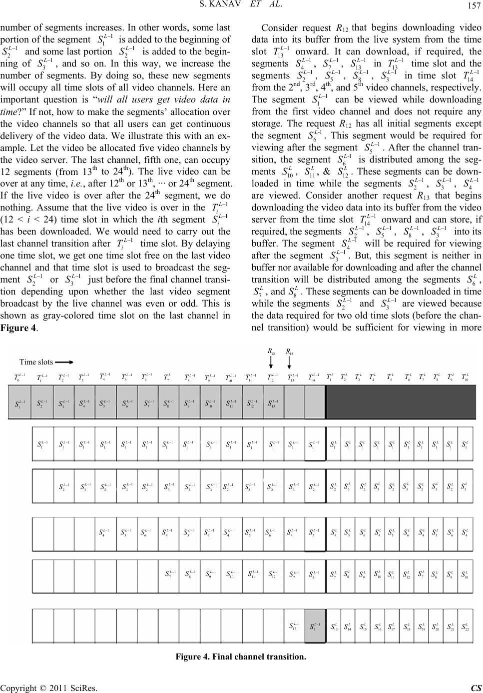 S. KANAV ET AL. Copyright © 2011 SciRes. CS 157 number of segments increases. In other words, some last portion of the segment 1 1 S is added to the beginning of 1 2 S and some last portion 1 2 S is added to the begin- ning of 1 3 S, and so on. In this way, we increase the number of segments. By doing so, these new segments will occupy all time slots of all video channels. Here an important question is “will all users get video data in time?” If not, how to make the segments’ allocation over the video channels so that all users can get continuous delivery of the video data. We illustrate this with an ex- ample. Let the video be allocated five video channels by the video server. The last channel, fifth one, can occupy 12 segments (from 13th to 24th). The live video can be over at any time, i.e., after 12th or 13th, ··· or 24th segment. If the live video is over after the 24th segment, we do nothing. Assume that the live video is over in the 1 i T (12 < i < 24) time slot in which the ith segment 1 i S has been downloaded. We would need to carry out the last channel transition after 1 i T time slot. By delaying one time slot, we get one time slot free on the last video channel and that time slot is used to broadcast the seg- ment 1 2 S or 1 3 S just before the final channel transi- tion depending upon whether the last video segment broadcast by the live channel was even or odd. This is shown as gray-colored time slot on the last channel in Figure 4. Consider request R12 that begins downloading video data its buffer from the live system from the time slot 1 13 into T cdown, if required, the segments onward. Itan load 1 4 S , 1 7 S , 3 1 1 S in 1 13 T time slot and t segments 1 2 he S , 1 5 S , 1 8 S , 1 3 S in time slot 1 14 T from the 2nd, 3rd , and 5th video channels, respectively. The segment 1 1 , 4th S can be viewed while downloading from the first video channel and does not require any storage. The rest R12 has all initial segments except the segment -1 6 equ S. This segmt would be required for viewing after the segt 1 5 en men S. After the channel tran- sition, tseent 6 he gm-1 S is distributed among the seg- ments 10 S, 11 S, & 12 S. These segments can d loaded in time while the segments 1 2 be own- S, 1 3 S , 1 4 S are viewed. Consider another request R13 that begins downloading the video data i its buffer from the video server from the time slot 1 n 14 to T 1 2 onrd care, if required, the segments wa andn sto S , 1 5 S, 1 8 S, 1 3 S into its buffer. The segment 1 4 S will be required for viewing after the segment 1 3 S . But, this segment is neither in buffer nor available for downloading and after the channel siwill be distributed among the segments 6 tran tion S, 7 S, and 8 S. These segments can be dowaded in time while the segments 1 2 nlo S and 1 3 S are viewed because the data required for two old time slots (before the chan- nel transition) would be sufficient for viewing in more 1 0 L T 1 2 L S 12 R Time slots 13 R 1 1 L T1 2 L T 1 3 L T1 4 L T 1 5 L T1 6 L T 7 L T1 8 L T 1 9 L T 1 10 L T 1 11 L T 1 12 L T 1 13 L T 1 14 L T 1 L T2 L T3 L T 4 L T 5 L T 6 L T 7 L T 8 L T9 L T10 L T 1 1 L S1 3 L S 1 4 L S1 5 L S 1 6 L S 1 7 L S1 8 L S 1 9 L S 1 10 L S 1 11 L S 1 12 L S 1 13 L S 1 1 L S1 1 L S1 1 L S 1 1 L S1 1 L S 1 1 L S1 1 L S1 1 L S 1 1 L S 1 1 L S 1 1 L S 1 1 L S 1 1 L S 1 1 L S 1 L S1 L S1 L S1 L S 1 L S 1 L S 1 L S 1 L S1 L S1 L S 1 2 L S1 3 L S 2 L S3 L S2 L S 3 L S 2 L S 3 L S 2 L S 3 L S2 L S3 L S 1 2 L S 1 3 L S 1 2 L S 1 3 L S1 2 L S 1 3 L S 1 2 L S 1 3 L S 1 2 L S 1 3 L S 1 2 L S 1 4 L S 1 5 L S 1 6 L S 1 4 L S1 5 L S 1 6 L S 1 4 L S 1 5 L S 1 6 L S 1 4 L S 1 5 L S 4 L S5 L S6 L S 4 L S5 L S 6 L S 4 L S 5 L S6 L S4 L S 1 7 L S 1 8 L S 1 9 L S 1 10 L S 1 11 L S 1 12 L S 1 7 L S 1 8 L S 7 L S8 L S9 L S 10 L S 11 L S12 L S 7 L S8 L S9 L S10 L S 1 13 L S 1 3 L S 13 L S14 L S15 L S16 L S 17 L S 18 L S 19 L S 20 L S21 L S22 L S Figure 4. Final channel transition.  158 an three new time slots (after the channel S. KANAV ET AL. th transition). If any problem related to the data availability is there, it will be for the 1 4 S segment. The request which may have problem ofa availability is one that starts re- ceiving video data from the time slot just before the channel transition. For other requests whether received before or after the channel transition, there is no problem of data availability. Figure 4 shows the final channel transition when the live video is over just after the live system has broadcast the segment 1 13 dat S in 1 13 T time slot. Consider another case when the vid over after the segment 1 14 liveeo is S has been broadcast by the live system. We need toform channel transition after the time slot 1 15 per T (it is not shown in figure because of size). The reque can download, if required, the segments 1 3 st R14 S, 1 6 S, 1 9 S, 1 2 S in time 1 15 T time slot before titiIt howevees not have the segment 1 4 the channelranson. r do S, which is a part of the segments 6 S and 7 S. Thesments can be downloaded into ber in e while the segments 1 2 e seguff tim S and 1 3 S are viewed because the duration of theseo segm (i.e., 1 2 twents S & 1 3 S) is more than that of the three new segmentster hannel transition). So, the segments 6 (af the c S and 7 S can be downloaded in time. Consider anotr request, say R21, which receives video data from the video server from the time slot 1 22 he T onward. In 1 22 T time slot, the segments 1 2 S, 5 1 S1 8 , S, 1 3 S cane downloaded, if required b , but the segment 4 1 S is not in buffer and after the channel transition this segment gets distributed among the segments 4 S and 5 S. These segments can be downloaded in timehen thegments 1 2 we s S & 1 3 S are viewed. Now the only point to resolve ihat ments after the channel transition are into which the segment 1 4 s “w seg- S is distributed.” The smallest and largest indices o segments (after the channel transition), denoted by IS and IL, which contain the data of seg- ment 1 4 f new S are given by IS =ch that n su * min np 3 nK and IL = n such that * min 4 n np K where p is the index of the last segment broadcast by the by live system and K is the number of video segments. For example, consider that the last segment broadcast the live system is 1 16 S. The request R16 receives video data from the viderver in 1 17 o se T time slot on- ward, the segment 1 4 Swould be disted among the segments 5 tribu S and 6 S. This can easily be verified as follows: 111 112 1232 1 8 16 ;;; 24 2424 LL LLLL SS SSSS 16 L S 111 425 3464 1 8 16 ;;. 24 2424 L LLLL S SSSS 16 LL SS 4. Results and Discussion he conservative scheme provides video data to users in e does not. That is the onservative scheme for T time, whereas the staircase schem eason we have considered the cr live video broadcasting. Another important characteris- tics of this scheme is that the number of segments occu- pied by a video channel Ci is the sum of all the segments transmitted by all video channels having indices 1, 2, ···, i − 1. Because of this the channel transition can be done at optimal time point, i.e., the transition can be delayed till all time slots of all video channels have been occu- pied. The buffer storage requirement depends upon the arrival time of the request, but in no case it can be more than 50% of the video length. Consider Figure 5 in which the gray-colored channel is the live channel and the dark black line in each channel is the channel transi- tion point. Using similar discussions, we can find out the buffer requirement for any request. Table 1 shows the buffer requirements for different requests (referring to Figure 5) for allocating five video channels to the video. In Table 2, for R12 and R13 requests, there are two dif- ferent storage requirements. If the live video is over after the 24th segment, then it is 11S and 11S, respectively; oth3 werwise 12S and 1S. Theaiting time in this scheme is pre-decided for the initial users and remains same till the channel transition time. After every channel transi- tion except the last one the waiting time becomes double. When the live transmission is over, the final channel transition is carried out and then the user’s waiting time is stabilized. We can find out how many and what the initial time slots are in a new time slot after the live vid- eo is over. The size of a time slot after the channel tran- sition except the last one becomes double. If Ti and 1 i T are the ith time slots before and after the first channel transition, then we have the following relation: 1 24 2124 2 ii i TT T In general, we have -1 -1 242 -1242,for,2, ,1, kk k iii TT TkL 1 (1) we very first ith time slot, i.e., here i T denotes th 0T 0 ii T and L specifies the final channel transition. te that till the final but one channel tran e slo tio It is to nosition the timts become double of the previous ones. We can find the size of a time slot after any channel transi- n in terms of the original time slots. For example, con- sider fourth channel transition (assuming it is not the last channel transition). Then, from (1), we have Copyright © 2011 SciRes. CS 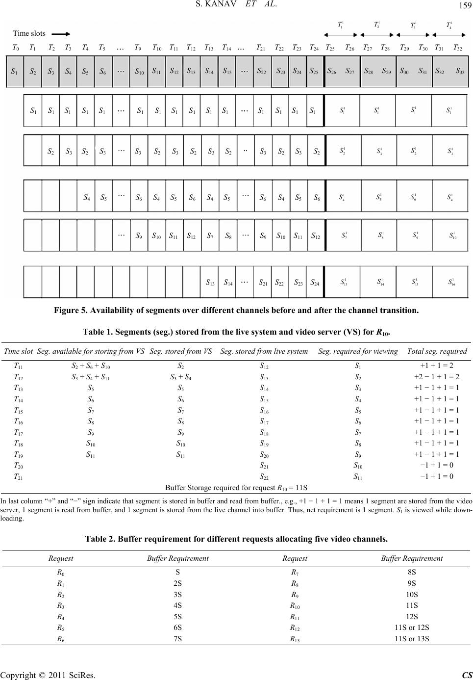 S. KANAV ET AL. 159 Time slots T 1 T 2 1 1 T1 2 T 1 3 T T 0 T 3 T 4 T 5 T 9 T 10 T 11 T 12 T 13 T 14 S 1 S 3 S 2 1 2 S 1 1 S 1 4 T T 21 T 22 T 23 T 24 T 25 T 26 T 27 T 28 T 29 T 30 T 31 T 32 S 4 S 5 S 6 S 10 S 11 S 12 S 13 S 14 S 15 S 22 S 23 S 24 S 25 S 26 S 27 S 28 S 29 S 30 S 31 S 32 S 33 S 1 S 1 S 1 S 1 S 1 S 1 S 1 S 1 S 1 S 1 S 1 S 1 S 1 S 1 S 1 1 1 S 1 1 S 1 1 S S 3 S 2 S 3 S 2 S 3 S 2 S 3 S 2 S 3 S 2 S 3 S 2 S 3 S 2 1 3 S1 2 S1 3 S S 4 S 5 S 6 S 4 S 5 S 6 S 4 S 5 S 4 S 5 S 6 S 6 1 4 S1 5 S 1 6 S1 4 S S 10 S 11 S 12 S 9 S 7 S 8 S 10 S 11 S 12 S 9 1 7 S1 8 S 1 9 S 1 10 S S 13 S 14 S 22 S 23 S 24 S 21 1 13 S1 14 S1 15 S1 16 S Figure 5. Availability of segments over different channels before and after the channel transition. Table 1. Segments (seg.) stored from the live system and video server (VS) for R10. Seg. available for storing from . requiredTime slot VS Seg. stored from VSSeg. stored from live systemSeg. required for viewing Total seg T11 S2 +1 + 1 = 2 + S6 + S10 S2 S12 S1 T12 S3 + S4 + S11 S3 + S4 S13 S2 +2 − 1 + 1 = 2 + Bu uired for request R10 = 11S T13 S5 S5 S14 S3 +1 − 1 + 1 = 1 T14 S6 S6 S15 S4 1 − 1 + 1 = 1 T15 S7 S7 S16 S5 +1 − 1 + 1 = 1 T16 S8 S8 S17 S6 +1 − 1 + 1 = 1 T17 S9 S9 S18 S7 +1 − 1 + 1 = 1 T18 S10 S10 S19 S8 +1 − 1 + 1 = 1 T19 S11 S11 S20 S9 +1 − 1 + 1 = 1 T20 S21 S10 −1 + 1 = 0 T21 S22 S11 −1 + 1 = 0 ffer Storage req In llumn “+” and “−” si indicate that segment is sto in buffer and read fromer., e.g., +1 − 1 + 1 = 1 me segment are stoideo servsegment is read fromuffer, and 1 segment is stor from the live channel inffer. Thus, net requiremengment. S1 is vieown- load Request Buffer Requirement Request Buffer Requirement ast cognred buffans 1red from the v er, 1 ing. bedto but is 1 sewed while d Table 2. Buffer requirement for different requests allocating five video channels. R0 8S S R7 R1 2S R8 9S 11SS 11SS R2 3S R9 10S R3 4S R10 11S R4 5S R11 12S R5 6S R12 or 12 R6 7S R13 or 13 Copyright © 2011 SciRes. CS  S. KANAV ET AL. 160 i (2) We can tak 1 because after any chansition ll time slots are of same durations. Thus, we have from (2), Again , and are needed and they are give We need , and an 0 Here denote original time slots. So, we have me sLth) is s ofan- sition, where 0.5 < 43 3 24 2-1242 ii TT T e i =nel tran a 433 12526 TTT We now need 3 T and 3 T, which are given by 25 32 26 2 22 2524 4924 5074 32 222 24 24 ; . TT TTT TT TTT 73 26515275 76 2 2 73 T, n by 2 74 T, 2 75 T76 T 2111 1 732414524 146169170 21 14724 148171172 2111 1 752414924 150173174 2111 1 7624 15124 152175176 TTTT T TT TTTTT TTTT T 11 1 74 24TTT 1 169 T, d they 1 170 T, are gi 10 1 171 T, ven by 1 172 T, 1 173 T, 0 1 174 T, 0 1 175 T 1 176 T, 0 24 33724 338361362 10 0 363 364 10 000 17124 34124 342365366 10 00 17224 34324 344367368 10 000 1732434524 346369370 10 0 17424 34724 348 TT TTT TT TT TTT TT TTT TT TTT TT TT 00 371 372 10 000 175 2434924350 373374 10 000 17624 35124 352375376 T TT TTT TT TTT 169 00 17024 33924 340 TT T 0 i Ts 4 1361 362376 TT TT The tilot after the final channel transition (i.e., α time a time slot of that of (L − 1)th channel tr α < 1. The value of α 0.5 means that th mined in aWhen the live video er, the entire video datastributed on all c per the scheme’s basic architecture. o the sum of all segments transmitted by all lower- his characteristic has been exploited ism for the live video. Providing live = e live video was over at the time when all time slots of all video channels had been occupied by the segments. In that case the last channel transition was not required. This situation is exactly same for α = 1. If α = 1, then the live video transmission is over just after all time slots of all the channels have been occupied. In this case, the user’s waiting time is unchanged. It means that after the final but one channel transition, the number of segments is such that all time slots of the last channel have been occupied and we need not do anything. Here we have discussed for values of α = 0.5 and 1. The exact value of α for other cases will depend on when the live video is over. Since we do not know in advance when the live video will be over, the exact value of α cannot be deter- In other broadcasting schemes including the conserva- tive staircase scheme the user waiting time is decided by the bandwidth allocated to the video, i.e., the size of a video segment, whereas in the proposed scheme it varies after every channel transition. The initial waiting time is decided by the service provider. As we know that the segment size becomes double of the previous size after ev dvance. is ov is dihannels as ery channel transition except the last channel transition, so is the user’s waiting time. As far as performance of the proposed scheme is concerned, there does not seem to appear alternative work in literature to make a mean- ingful comparison and hence the comparison is not pos- sible. 5. Conclusions In this paper, we have proposed a technique for support- ing the live video in the conservative scheme. The im- portant characteristics of the conservative scheme is that the number of segments transmitted by a video channel is qual te indexed channels. T o develop a mechant video services has wide applications, such as cricket match, interactive education session, etc. 6. References [1] Y.-C. Tseng, M.-H. Yang and C.-H. Chang, “A Recursive Frequency-Splitting Scheme for Broadcasting Hot Videos in VOD Service,” IEEE Transactions on Communica- tions, Vol. 50, No. 8, 2002, pp. 1348-1355. doi:10.1109/TCOMM.2002.801466 [2] W. F. Poona, K.-T. tion for Video- Lo and J. Feng, “First Segment Parti- on-Demand Broadcasting Protocols,” Com- puter Communications, Vol. 26, No. 14, 2003, pp. 1698- 1708. doi:10.1016/S0140-3664(02)00264-5 [3] S. Vishwanathan and T. Imielinski, “Metropolitan Area Video on Demand Service Using Pyramid Broadcasting,” Multimedia Systems, Vol. 4, No. 4, 1996, pp. 197-208. doi:10.1007/s005300050023 [4] L. Gao, J. Kurose and D. Towsley, “Efficient Schemes for Broadcasting Popular Videos,” Multimedia Systems, Vol. 8, No. 4, 2002, pp. 284-294. doi:10.1007/s005300100049 [5] Ch.-L. Chan, S.-Y. Huang, T.-C. Su and J.-S. Wang, “Buffer-Assisted on-Demand Multicast for VOD Appli- cations,” Multimedia Systems, Vol. 12, No. 2, 2006, pp 89-100. . 06-0041-1doi:10.1007/s00530-0 l Joint Confer- [6] S. Ramesh, I. Rhee and K. Guo, “Multicast with Cache (Mcache): An Adaptive Zero-Delay Video-on-Demand Service,” IEEE Proceedings of 2th Annua Copyright © 2011 SciRes. CS  S. KANAV ET AL. 161 munications Societies, Vol o. 3, 1997, pp. mmunication ystems,” ACM SIGCOMM Computer Commu- ence of the Computer and Com . 1, Anchorage, 22-26 April 2001, pp. 85-94. [7] L. S. Juhn and L.-M. Tseng, “Harmonic Broadcasting Scheme for Video-on-Demand Service,” IEEE Transac- tions on Consumer Electronics, Vol. 43, N 268-271. [8] J.-F. Paris, S. W. Carter and D. D. E. Long, “Efficient Broadcasting Protocols for Video on Demand,” Proceed- ings of 6th International Symposium on Modeling, Analy- sis and Simulation of Computer and Teleco Systems, Montreal, 19-24 July 1998, pp. 127-132. [9] K. A. Hua and S. Sheu, “Skyscraper Broadcasting: A New Broadcasting Scheme for Metropolitan Video on Demand S nication Review, Vol. 27, No. 4, 1997, pp. 89-100. doi:10.1145/263109.263144 [10] Z. Q. Gu and S. Y. Yu, “Conservative Staircase Data Broadcasting Protocol for Video on Demand,” IEEE Transactions on Consumer Electronics, Vol. 49, N 2003, pp. 1073-1077. o. 4, 109/TCE.2003.1261198doi:10.1 [11] L. S. Juhn and L. M. Tseng, “Fast Data Broadcasting and Receiving for Popular Video Service,” IEEE Transac- tions on Broadcasting, Vol. 44, No. 1, 1998, pp. 100-105. doi:10.1109/11.713059 [12] L. S. Juhn and L. M. Tseng, “Staircase Data Broadcasting and Receiving Scheme for Hot Video Service,” IEEE Transactions on Consumer Electronics, Vol. 43, No. 4, 1997, pp. 1110-1117. doi:10.1109/30.642378 [13] S. Chand, “Live Video Services Using Fast Broadcasting Scheme,” Journal of Communications and Network, Vol. 2, No. 1, 2010, pp. 79-85. doi:10.4236/cn.2010.21013 Copyright © 2011 SciRes. CS
|