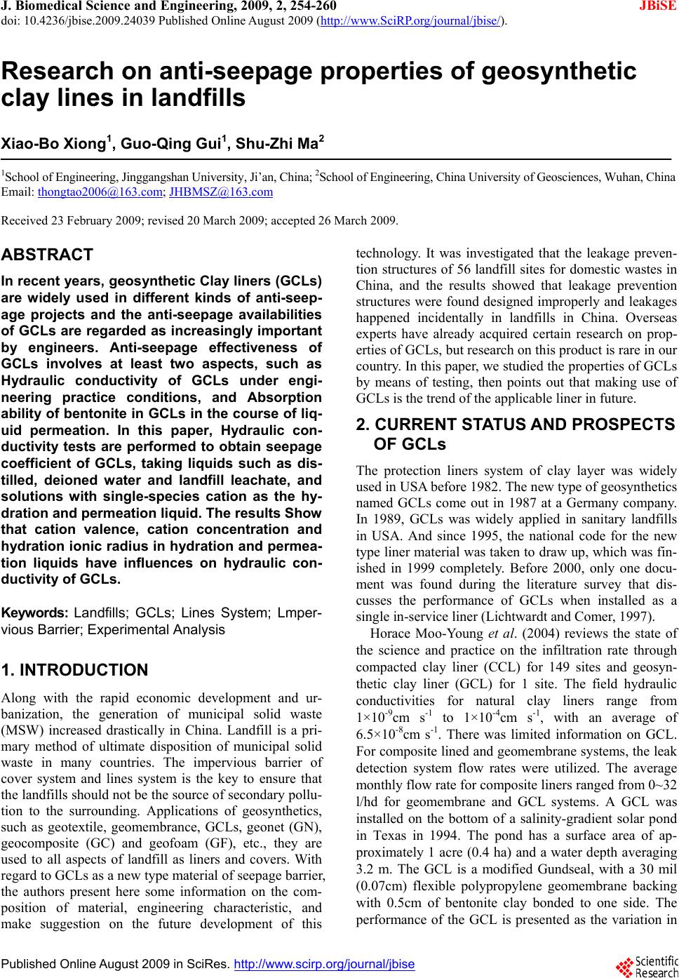
 J. Biomedical Science and Engineering, 2009, 2, 254-260 doi: 10.4236/jbise.2009.24039 Published Online August 2009 (http://www.SciRP.org/journal/jbise/ JBiSE ). Published Online August 2009 in SciRes. http://www.scirp.org/journal/jbise Research on anti-seepage properties of geosynthetic clay lines in landfills Xiao-Bo Xiong1, Guo-Qing Gui1, Shu-Zhi Ma2 1School of Engineering, Jinggangshan University, Ji’an, China; 2School of Engineering, China University of Geosciences, Wuhan, China Email: thongtao2006@163.com; JHBMSZ@163.com Received 23 February 2009; revised 20 March 2009; accepted 26 March 2009. ABSTRACT In recent years, geosynthetic Clay liners (GCLs) are widely used in different kinds of anti-seep- age projects and the anti-seepage availabilities of GCLs are regarded as increasingly important by engineers. Anti-seepage effectiveness of GCLs involves at least two aspects, such as Hydraulic conductivity of GCLs under engi- neering practice conditions, and Absorption ability of bentonite in GCLs in the course of liq- uid permeation. In this paper, Hydraulic con- ductivity tests are performed to obtain seepage coefficient of GCLs, taking liquids such as dis- tilled, deioned water and landfill leachate, and solutions with single-species cation as the hy- dration and permeation liquid. The results Show that cation valence, cation concentration and hydration ionic radius in hydration and permea- tion liquids have influences on hydraulic con- ductivity of GCLs. Keywords: Landfills; GCLs; Lines System; Lmper- vious Barrier; Experimental Analysis 1. INTRODUCTION Along with the rapid economic development and ur- banization, the generation of municipal solid waste (MSW) increased drastically in China. Landfill is a pri- mary method of ultimate disposition of municipal solid waste in many countries. The impervious barrier of cover system and lines system is the key to ensure that the landfills should not be the source of secondary pollu- tion to the surrounding. Applications of geosynthetics, such as geotextile, geomembrance, GCLs, geonet (GN), geocomposite (GC) and geofoam (GF), etc., they are used to all aspects of landfill as liners and covers. With regard to GCLs as a new type material of seepage barrier, the authors present here some information on the com- position of material, engineering characteristic, and make suggestion on the future development of this technology. It was investigated that the leakage preven- tion structures of 56 landfill sites for domestic wastes in China, and the results showed that leakage prevention structures were found designed improperly and leakages happened incidentally in landfills in China. Overseas experts have already acquired certain research on prop- erties of GCLs, but research on this product is rare in our country. In this paper, we studied the properties of GCLs by means of testing, then points out that making use of GCLs is the trend of the applicable liner in future. 2. CURRENT STATUS AND PROSPECTS OF GCLs The protection liners system of clay layer was widely used in USA before 1982. The new type of geosynthetics named GCLs come out in 1987 at a Germany company. In 1989, GCLs was widely applied in sanitary landfills in USA. And since 1995, the national code for the new type liner material was taken to draw up, which was fin- ished in 1999 completely. Before 2000, only one docu- ment was found during the literature survey that dis- cusses the performance of GCLs when installed as a single in-service liner (Lichtwardt and Comer, 1997). Horace Moo-Young et al. (2004) reviews the state of the science and practice on the infiltration rate through compacted clay liner (CCL) for 149 sites and geosyn- thetic clay liner (GCL) for 1 site. The field hydraulic conductivities for natural clay liners range from 1×10⁻⁹cm s-1 to 1×10⁻⁴cm s-1, with an average of 6.5×10⁻⁸cm s-1. There was limited information on GCL. For composite lined and geomembrane systems, the leak detection system flow rates were utilized. The average monthly flow rate for composite liners ranged from 0~32 l/hd for geomembrane and GCL systems. A GCL was installed on the bottom of a salinity-gradient solar pond in Texas in 1994. The pond has a surface area of ap- proximately 1 acre (0.4 ha) and a water depth averaging 3.2 m. The GCL is a modified Gundseal, with a 30 mil (0.07cm) flexible polypropylene geomembrane backing with 0.5cm of bentonite clay bonded to one side. The performance of the GCL is presented as the variation in 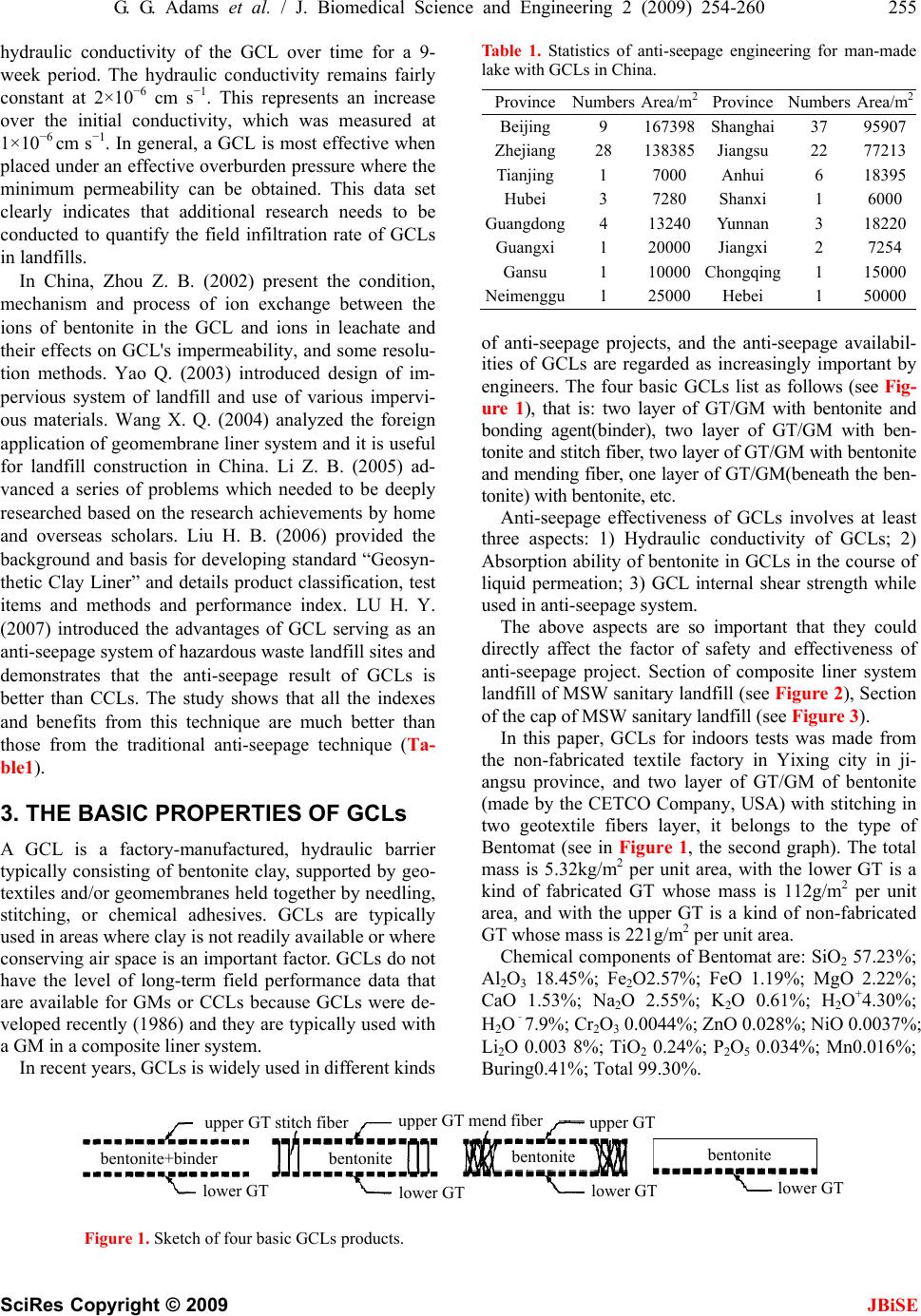 G. G. Adams et al. / J. Biomedical Science and Engineering 2 (2009) 254-260 255 SciRes Copyright © 2009 JBiSE hydraulic conductivity of the GCL over time for a 9- week period. The hydraulic conductivity remains fairly constant at 2×10⁻⁶ cm s−1. This represents an increase over the initial conductivity, which was measured at 1×10⁻⁶ cm s−1. In general, a GCL is most effective when placed under an effective overburden pressure where the minimum permeability can be obtained. This data set clearly indicates that additional research needs to be conducted to quantify the field infiltration rate of GCLs in landfills. In China, Zhou Z. B. (2002) present the condition, mechanism and process of ion exchange between the ions of bentonite in the GCL and ions in leachate and their effects on GCL's impermeability, and some resolu- tion methods. Yao Q. (2003) introduced design of im- pervious system of landfill and use of various impervi- ous materials. Wang X. Q. (2004) analyzed the foreign application of geomembrane liner system and it is useful for landfill construction in China. Li Z. B. (2005) ad- vanced a series of problems which needed to be deeply researched based on the research achievements by home and overseas scholars. Liu H. B. (2006) provided the background and basis for developing standard “Geosyn- thetic Clay Liner” and details product classification, test items and methods and performance index. LU H. Y. (2007) introduced the advantages of GCL serving as an anti-seepage system of hazardous waste landfill sites and demonstrates that the anti-seepage result of GCLs is better than CCLs. The study shows that all the indexes and benefits from this technique are much better than those from the traditional anti-seepage technique (Ta- ble1). 3. THE BASIC PROPERTIES OF GCLs A GCL is a factory-manufactured, hydraulic barrier typically consisting of bentonite clay, supported by geo- textiles and/or geomembranes held together by needling, stitching, or chemical adhesives. GCLs are typically used in areas where clay is not readily available or where conserving air space is an important factor. GCLs do not have the level of long-term field performance data that are available for GMs or CCLs because GCLs were de- veloped recently (1986) and they are typically used with a GM in a composite liner system. In recent years, GCLs is widely used in different kinds Table 1. Statistics of anti-seepage engineering for man-made lake with GCLs in China. ProvinceNumbers Area/m2 Province NumbersArea/m2 Beijing 9 167398 Shanghai 37 95907 Zhejiang28 138385 Jiangsu 22 77213 Tianjing1 7000Anhui 6 18395 Hubei 3 7280Shanxi 1 6000 Guangdong4 13240Yunnan 3 18220 Guangxi1 20000Jiangxi 2 7254 Gansu 1 10000Chongqing 1 15000 Neimenggu1 25000Hebei 1 50000 of anti-seepage projects, and the anti-seepage availabil- ities of GCLs are regarded as increasingly important by engineers. The four basic GCLs list as follows (see Fig- ure 1), that is: two layer of GT/GM with bentonite and bonding agent(binder), two layer of GT/GM with ben- tonite and stitch fiber, two layer of GT/GM with bentonite and mending fiber, one layer of GT/GM(beneath the ben- tonite) with bentonite, etc. Anti-seepage effectiveness of GCLs involves at least three aspects: 1) Hydraulic conductivity of GCLs; 2) Absorption ability of bentonite in GCLs in the course of liquid permeation; 3) GCL internal shear strength while used in anti-seepage system. The above aspects are so important that they could directly affect the factor of safety and effectiveness of anti-seepage project. Section of composite liner system landfill of MSW sanitary landfill (see Figure 2), Section of the cap of MSW sanitary landfill (see Figure 3). In this paper, GCLs for indoors tests was made from the non-fabricated textile factory in Yixing city in ji- angsu province, and two layer of GT/GM of bentonite (made by the CETCO Company, USA) with stitching in two geotextile fibers layer, it belongs to the type of Bentomat (see in Figure 1, the second graph). The total mass is 5.32kg/m2 per unit area, with the lower GT is a kind of fabricated GT whose mass is 112g/m2 per unit area, and with the upper GT is a kind of non-fabricated GT whose mass is 221g/m2 per unit area. Chemical components of Bentomat are: SiO2 57.23%; Al2O3 18.45%; Fe2O2.57%; FeO 1.19%; MgO 2.22%; CaO 1.53%; Na2O 2.55%; K2O 0.61%; H2O+4.30%; H2O–7.9%; Cr2O3 0.0044%; ZnO 0.028%; NiO 0.0037%; Li2O 0.003 8%; TiO2 0.24%; P2O5 0.034%; Mn0.016%; Buring0.41%; Total 99.30%. Figure 1. Sketch of four basic GCLs products. u er GT stitch fibe u er GT men fibe u er GT entonite entonite entonite entonite+binde lower GT lower GT lower GT lower GT 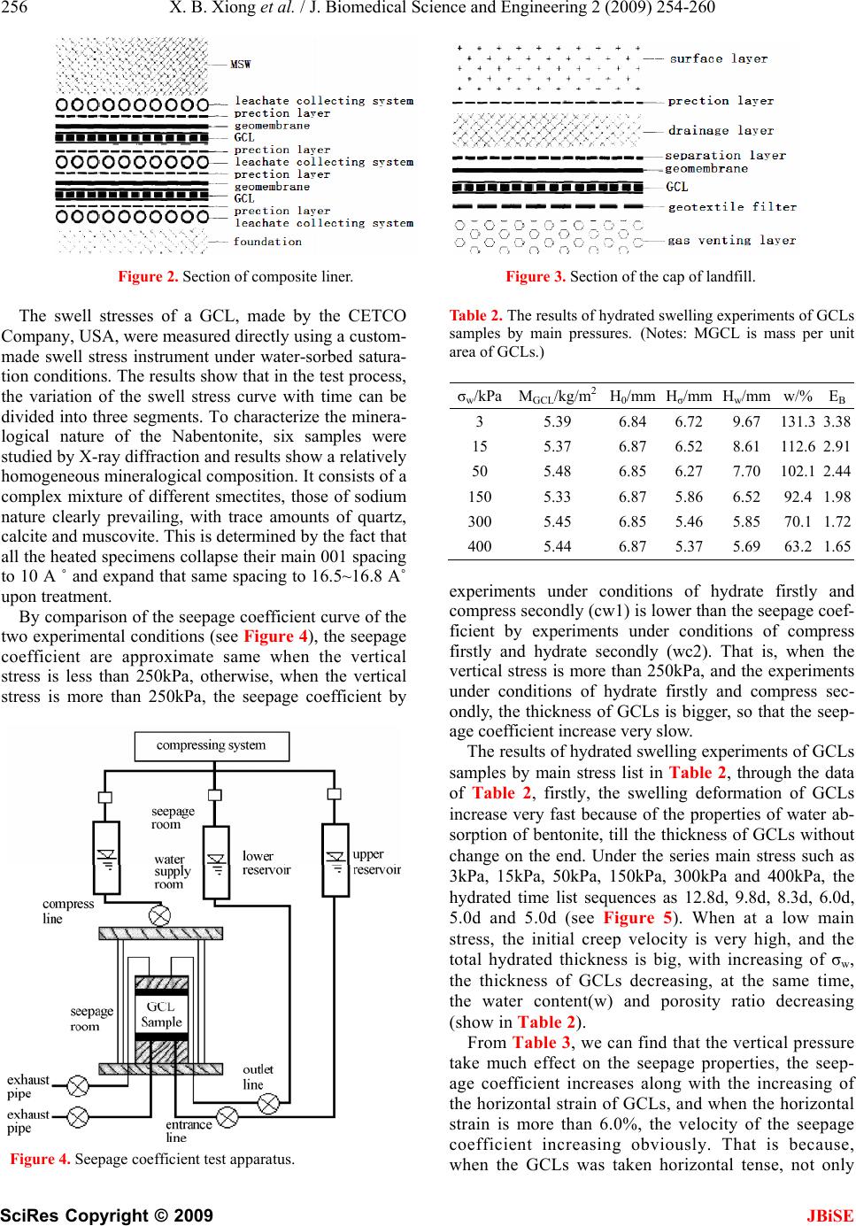 256 X. B. Xiong et al. / J. Biomedical Science and Engineering 2 (2009) 254-260 SciRes Copyright © 2009 JBiSE Figure 2. Section of composite liner. Figure 3. Section of the cap of landfill. The swell stresses of a GCL, made by the CETCO Company, USA, were measured directly using a custom- made swell stress instrument under water-sorbed satura- tion conditions. The results show that in the test process, the variation of the swell stress curve with time can be divided into three segments. To characterize the minera- logical nature of the Nabentonite, six samples were studied by X-ray diffraction and results show a relatively homogeneous mineralogical composition. It consists of a complex mixture of different smectites, those of sodium nature clearly prevailing, with trace amounts of quartz, calcite and muscovite. This is determined by the fact that all the heated specimens collapse their main 001 spacing to 10 A ˚ and expand that same spacing to 16.5~16.8 A˚ upon treatment. By comparison of the seepage coefficient curve of the two experimental conditions (see Figure 4), the seepage coefficient are approximate same when the vertical stress is less than 250kPa, otherwise, when the vertical stress is more than 250kPa, the seepage coefficient by Figure 4. Seepage coefficient test apparatus. Table 2. The results of hydrated swelling experiments of GCLs samples by main pressures. (Notes: MGCL is mass per unit area of GCLs.) σw/kPa MGCL/kg/m2H0/mm Hσ/mm Hw/mm w/%EB 3 5.39 6.84 6.72 9.67 131.33.38 15 5.37 6.87 6.52 8.61 112.62.91 50 5.48 6.85 6.27 7.70 102.12.44 150 5.33 6.87 5.86 6.52 92.41.98 300 5.45 6.85 5.46 5.85 70.11.72 400 5.44 6.87 5.37 5.69 63.21.65 experiments under conditions of hydrate firstly and compress secondly (cw1) is lower than the seepage coef- ficient by experiments under conditions of compress firstly and hydrate secondly (wc2). That is, when the vertical stress is more than 250kPa, and the experiments under conditions of hydrate firstly and compress sec- ondly, the thickness of GCLs is bigger, so that the seep- age coefficient increase very slow. The results of hydrated swelling experiments of GCLs samples by main stress list in Table 2, through the data of Table 2, firstly, the swelling deformation of GCLs increase very fast because of the properties of water ab- sorption of bentonite, till the thickness of GCLs without change on the end. Under the series main stress such as 3kPa, 15kPa, 50kPa, 150kPa, 300kPa and 400kPa, the hydrated time list sequences as 12.8d, 9.8d, 8.3d, 6.0d, 5.0d and 5.0d (see Figure 5). When at a low main stress, the initial creep velocity is very high, and the total hydrated thickness is big, with increasing of σw, the thickness of GCLs decreasing, at the same time, the water content(w) and porosity ratio decreasing (show in Table 2). From Table 3, we can find that the vertical pressure take much effect on the seepage properties, the seep- age coefficient increases along with the increasing of the horizontal strain of GCLs, and when the horizontal strain is more than 6.0%, the velocity of the seepage coefficient increasing obviously. That is because, when the GCLs was taken horizontal tense, not only 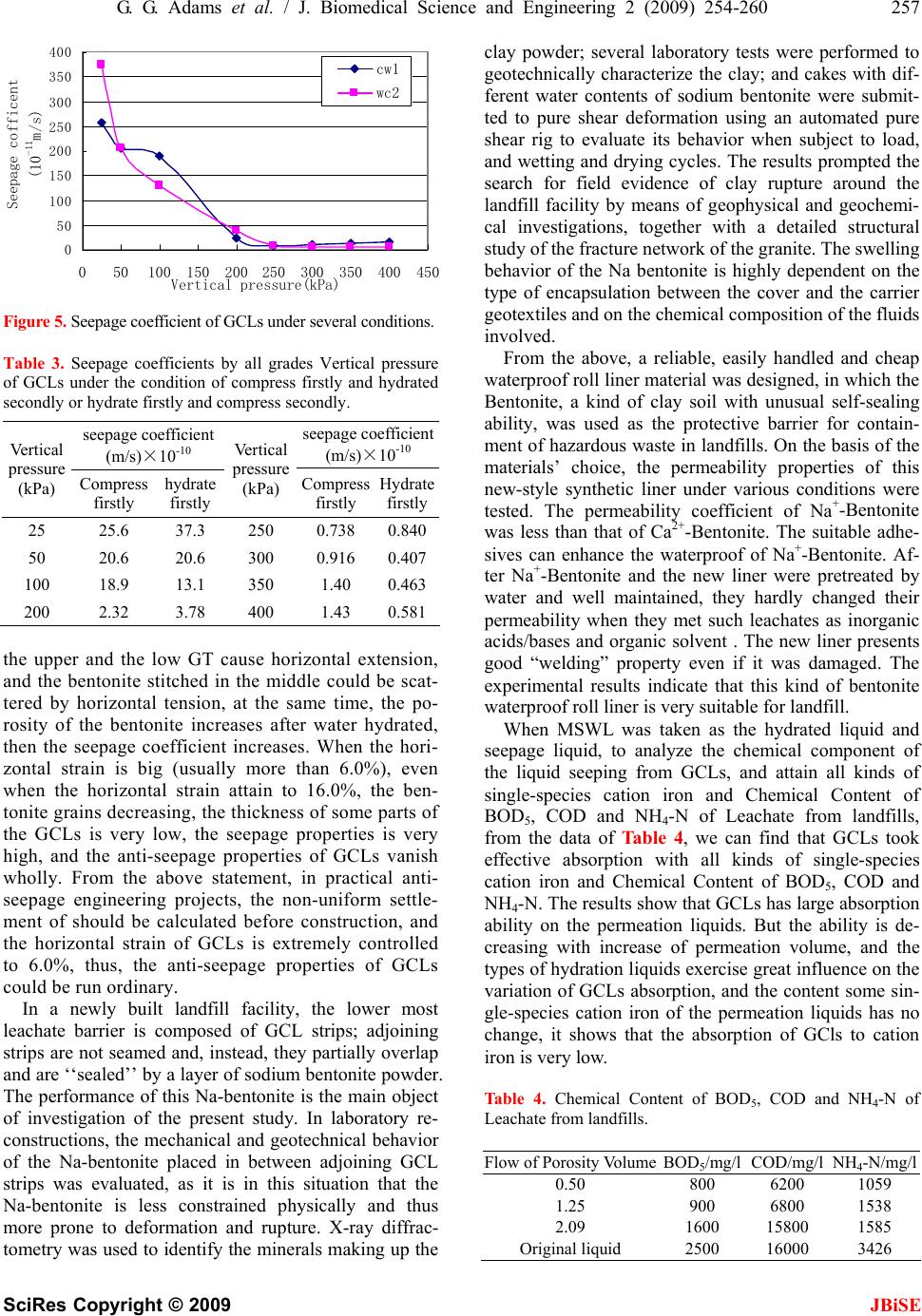 G. G. Adams et al. / J. Biomedical Science and Engineering 2 (2009) 254-260 257 SciRes Copyright © 2009 JBiSE 0 50 100 150 200 250 300 350 400 050100 150200250 300 350400 450 Vertical pressure(kPa) Seepage cofficent (10 -11 m/s) cw1 wc2 Figure 5. Seepage coefficient of GCLs under several conditions. Table 3. Seepage coefficients by all grades Vertical pressure of GCLs under the condition of compress firstly and hydrated secondly or hydrate firstly and compress secondly. seepage coefficient (m/s)×10-10 seepage coefficient (m/s)×10-10 Vertical pressure (kPa) Compress firstly hydrate firstly Vertical pressure (kPa) Compress firstly Hydrate firstly 25 25.6 37.3 250 0.738 0.840 50 20.6 20.6 300 0.916 0.407 100 18.9 13.1 350 1.40 0.463 200 2.32 3.78 400 1.43 0.581 the upper and the low GT cause horizontal extension, and the bentonite stitched in the middle could be scat- tered by horizontal tension, at the same time, the po- rosity of the bentonite increases after water hydrated, then the seepage coefficient increases. When the hori- zontal strain is big (usually more than 6.0%), even when the horizontal strain attain to 16.0%, the ben- tonite grains decreasing, the thickness of some parts of the GCLs is very low, the seepage properties is very high, and the anti-seepage properties of GCLs vanish wholly. From the above statement, in practical anti- seepage engineering projects, the non-uniform settle- ment of should be calculated before construction, and the horizontal strain of GCLs is extremely controlled to 6.0%, thus, the anti-seepage properties of GCLs could be run ordinary. In a newly built landfill facility, the lower most leachate barrier is composed of GCL strips; adjoining strips are not seamed and, instead, they partially overlap and are ‘‘sealed’’ by a layer of sodium bentonite powder. The performance of this Na-bentonite is the main object of investigation of the present study. In laboratory re- constructions, the mechanical and geotechnical behavior of the Na-bentonite placed in between adjoining GCL strips was evaluated, as it is in this situation that the Na-bentonite is less constrained physically and thus more prone to deformation and rupture. X-ray diffrac- tometry was used to identify the minerals making up the clay powder; several laboratory tests were performed to geotechnically characterize the clay; and cakes with dif- ferent water contents of sodium bentonite were submit- ted to pure shear deformation using an automated pure shear rig to evaluate its behavior when subject to load, and wetting and drying cycles. The results prompted the search for field evidence of clay rupture around the landfill facility by means of geophysical and geochemi- cal investigations, together with a detailed structural study of the fracture network of the granite. The swelling behavior of the Na bentonite is highly dependent on the type of encapsulation between the cover and the carrier geotextiles and on the chemical composition of the fluids involved. From the above, a reliable, easily handled and cheap waterproof roll liner material was designed, in which the Bentonite, a kind of clay soil with unusual self-sealing ability, was used as the protective barrier for contain- ment of hazardous waste in landfills. On the basis of the materials’ choice, the permeability properties of this new-style synthetic liner under various conditions were tested. The permeability coefficient of Na+-Bentonite was less than that of Ca2+-Bentonite. The suitable adhe- sives can enhance the waterproof of Na+-Bentonite. Af- ter Na+-Bentonite and the new liner were pretreated by water and well maintained, they hardly changed their permeability when they met such leachates as inorganic acids/bases and organic solvent . The new liner presents good “welding” property even if it was damaged. The experimental results indicate that this kind of bentonite waterproof roll liner is very suitable for landfill. When MSWL was taken as the hydrated liquid and seepage liquid, to analyze the chemical component of the liquid seeping from GCLs, and attain all kinds of single-species cation iron and Chemical Content of BOD5, COD and NH4-N of Leachate from landfills, from the data of Table 4, we can find that GCLs took effective absorption with all kinds of single-species cation iron and Chemical Content of BOD5, COD and NH4-N. The results show that GCLs has large absorption ability on the permeation liquids. But the ability is de- creasing with increase of permeation volume, and the types of hydration liquids exercise great influence on the variation of GCLs absorption, and the content some sin- gle-species cation iron of the permeation liquids has no change, it shows that the absorption of GCls to cation iron is very low. Table 4. Chemical Content of BOD5, COD and NH4-N of Leachate from landfills. Flow of Porosity VolumeBOD5/mg/l COD/mg/l NH4-N/mg/l 0.50 800 6200 1059 1.25 900 6800 1538 2.09 1600 15800 1585 Original liquid 2500 16000 3426 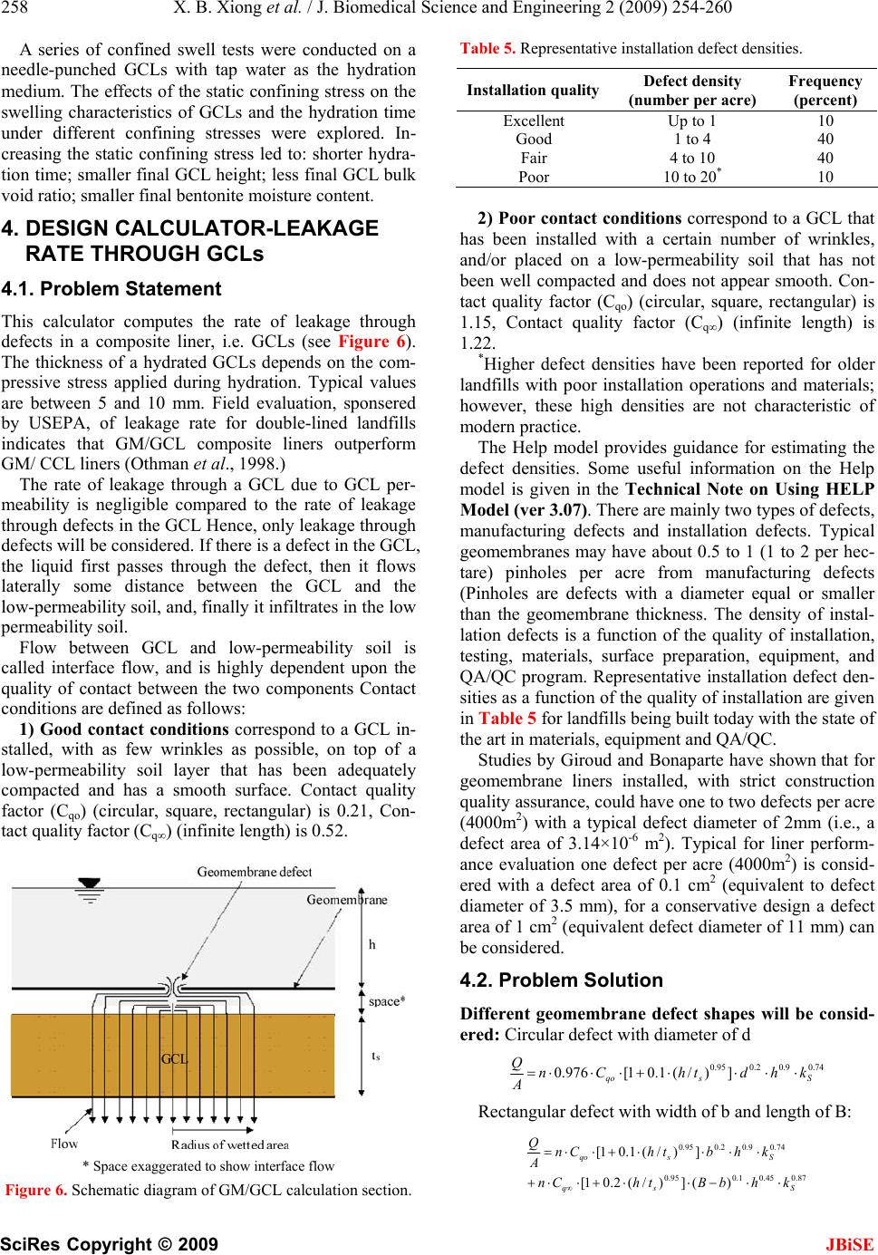 258 X. B. Xiong et al. / J. Biomedical Science and Engineering 2 (2009) 254-260 SciRes Copyright © 2009 JBiSE A series of confined swell tests were conducted on a needle-punched GCLs with tap water as the hydration medium. The effects of the static confining stress on the swelling characteristics of GCLs and the hydration time under different confining stresses were explored. In- creasing the static confining stress led to: shorter hydra- tion time; smaller final GCL height; less final GCL bulk void ratio; smaller final bentonite moisture content. 4. DESIGN CALCULATOR-LEAKAGE RATE THROUGH GCLs 4.1. Problem Statement This calculator computes the rate of leakage through defects in a composite liner, i.e. GCLs (see Figure 6). The thickness of a hydrated GCLs depends on the com- pressive stress applied during hydration. Typical values are between 5 and 10 mm. Field evaluation, sponsered by USEPA, of leakage rate for double-lined landfills indicates that GM/GCL composite liners outperform GM/ CCL liners (Othman et al., 1998.) The rate of leakage through a GCL due to GCL per- meability is negligible compared to the rate of leakage through defects in the GCL Hence, only leakage through defects will be considered. If there is a defect in the GCL, the liquid first passes through the defect, then it flows laterally some distance between the GCL and the low-permeability soil, and, finally it infiltrates in the low permeability soil. Flow between GCL and low-permeability soil is called interface flow, and is highly dependent upon the quality of contact between the two components Contact conditions are defined as follows: 1) Good contact conditions correspond to a GCL in- stalled, with as few wrinkles as possible, on top of a low-permeability soil layer that has been adequately compacted and has a smooth surface. Contact quality factor (Cqo) (circular, square, rectangular) is 0.21, Con- tact quality factor (Cq∞) (infinite length) is 0.52. * Space exaggerated to show interface flow Figure 6. Schematic diagram of GM/GCL calculation section. Table 5. Representative installation defect densities. Installation qualityDefect density (number per acre) Frequency (percent) Excellent Up to 1 10 Good 1 to 4 40 Fair 4 to 10 40 Poor 10 to 20* 10 2) Poor contact conditions correspond to a GCL that has been installed with a certain number of wrinkles, and/or placed on a low-permeability soil that has not been well compacted and does not appear smooth. Con- tact quality factor (Cqo) (circular, square, rectangular) is 1.15, Contact quality factor (Cq∞) (infinite length) is 1.22. *Higher defect densities have been reported for older landfills with poor installation operations and materials; however, these high densities are not characteristic of modern practice. The Help model provides guidance for estimating the defect densities. Some useful information on the Help model is given in the Technical Note on Using HELP Model (ver 3.07). There are mainly two types of defects, manufacturing defects and installation defects. Typical geomembranes may have about 0.5 to 1 (1 to 2 per hec- tare) pinholes per acre from manufacturing defects (Pinholes are defects with a diameter equal or smaller than the geomembrane thickness. The density of instal- lation defects is a function of the quality of installation, testing, materials, surface preparation, equipment, and QA/QC program. Representative installation defect den- sities as a function of the quality of installation are given in Table 5 for landfills being built today with the state of the art in materials, equipment and QA/QC. Studies by Giroud and Bonaparte have shown that for geomembrane liners installed, with strict construction quality assurance, could have one to two defects per acre (4000m2) with a typical defect diameter of 2mm (i.e., a defect area of 3.14×10⁻⁶ m 2). Typical for liner perform- ance evaluation one defect per acre (4000m2) is consid- ered with a defect area of 0.1 cm2 (equivalent to defect diameter of 3.5 mm), for a conservative design a defect area of 1 cm2 (equivalent defect diameter of 11 mm) can be considered. 4.2. Problem Solution Different geomembrane defect shapes will be consid- ered: Circular defect with diameter of d 74.09.02.095.0 ])/(1.01[976.0 Ssqo khdthCn Q Rectangular defect with width of b and length of B: 87.045.01.095.0 74.09.02.095.0 )(])/(2.01[ ])/(1.01[ Ssq Ssqo khbBthCn khbthCn A Q  G. G. Adams et al. / J. Biomedical Science and Engineering 2 (2009) 254-260 259 SciRes Copyright © 2009 JBiSE Q-Leakage rate through the considered geomembrane defect (m3/s); Q*-Leakage rate per unit length of geomembrane de- fect (m3/s.m); A-Considered geomembrane area (m2); N-Number of defects per considered geomembrane area (A); Co or Cq ∞-Contact quality factor (see Table 6); H-Hydraulic head on top of the geomembrane (m); ts-Thickness of the low-permeability soil component of the composite liner (m); D-Diameter of circular defect (m); b-Width of defect (m); B-Length of rectangular defect (m). Limitation of the equations presented: 1) If the effect is circular, the defect diameter should be no less than 0.5 mm and not greater than 25 mm. In the case of the defects that are not circular, it is proposed to use these limitations for the defect width. 2) The liquid head on top of the geomembrane should be equal to or less than 3 m. 4.3. Input Values Case 1: Geometry of circular defect ① Considered geomembrane area(A) is 4000m2; ② Hydraulic head on top of the geomembrane(m) is 0.3m; ③ Thickness of the low-permeability soil(m) is 2m; ④ Permeability of the low-permeability soil(m/s) is 1.0×10⁻⁷m/s. Properties of circular defect ① Contact (good or poor) Good; ② Number of de- fects (n) is 1; ③ Diameter of defect (d) is 0.0002m. Case 2: Geometry of Rectangular Defect Properties of Rectangular Defect Width of defect (b) is 0.002m; Length of defect (B) is 0.01m, the else conditions like Case 1. 5. CONCLUSIONS In this paper, a series of research work including about the laboratory tests of GCLs is conducted and several valuable conclusions are obtained: Table 6. Comparison between theoretical Case number Theoretical structure Practical anti- seep- age structure Maximum flow, m3/ (m2.d) Case1 One layer GM, eneath high seepage layer GM+ foundation with high permeability in- dex or geocomposite (such as geotextile) 3.14×10⁻³ Case2 One layer GM, eneath low seepage sub- stituted layer GM+geocomposite with low permeability index (such as GCL) 7.97×10⁻⁸ 1) A geosynthetic hydraulic conductivity device is de- signed to measure seepage coefficients of GCLs under constant normal stress conditions. Seepage coefficients of GCLs is measured for different hydrated and perme- ated liquids using the apparatus. Free swelling tests and hydration swelling tests of GCLs and bentonnite per- formed in order to research the swelling characteristics of GCLs and its influencing factors, including normal stress, loading-hydration sequence and hydration liquid. The results show that these factors have influences on GCLs swelling characteristics. Similar influencing laws can be obtained in the two tests. 2) Seepage coefficients tests are performed to obtain hydraulic conductivity of GCLs, taking liquids such as distilled, deioned water and landfill leachate, and solu- tions with single-species cation as the hydration and permeation liquid, the results show that cation valence, cation concentration and hydration ionic radius in hydra- tion and permeation liquids have influences on hydraulic conductivity of GCLs. The influences of stress condi- tions and loading-hydration sequence on GCLs hydraulic conductivity are researched, the results Show that nor- mal stress and horizontal strain, as well as load- ing-hydration sequence, all have influences on the vari- ety of hydraulic conductivity. 3) Absorption ability of GCLs in the course of liquid permeation is studied, and its influencing factors are also discussed, including hydration liquid and permeation time. The results show that GCLs has large absorption ability on the permeation liquids. But the ability is de- creasing with increase of permeation volume, and the types of hydration liquids exercise great influence on the variation of GCLs absorption. 4) Analysis are made to combine the conclusion ob- tained in this study with practical engineering projects, and proposals of building method of GCLs are ad- vanced. 6. ACKNOWLEDGEMENTS Some research results described in this paper were de- veloped by the author in his graduate study between 1997 and 2000 in Nanjing University. The author grate- fully acknowledges his teacher (Academician of Chinese Academy of Sciences Prof. Jun SUN) for his helpful direction and suggestion to the author during his study- ing in Tongji University. The authors would like to ex- press their thanks to many teachers and staffs at the uni- versity of tongji university, nanjing university, and china university of geosciences, and jinggangshan university for the help in presenting some related experimental data. REFERENCES [1] J. Sun, et al., (2005) Municipal environmental geotech- nical engineering [M]. Shanghai: Shanghai Scientific and  260 X. B. Xiong et al. / J. Biomedical Science and Engineering 2 (2009) 254-260 SciRes Copyright © 2009 JBiSE Technical Publishers. (In Chinese). [2] X. B. Xiong, (2000) Environmental geotechnical re- search on municipal sanitary landfill, Nanjing: Nanjing University. [3] B. Shi, et al., (2003) Environmental geotechnical prob- lems and their treatment of municipal sanitary landfills in the southeast of China, Journal of Disaster prevention and Mitigation Engineering, 23(4), 91-97. [4] H. Y. Fang, (2000) Environmental geotechnology per- spective in the 21st century, Chinese Journal of Geotech- nical Engineering, 22(1), 1-11. [5] Z. B. Li, (2007) Research on anti-seepage availability of geosynthetic clay liners and related mechanism analysis, Shanghai: Tongji University. [6] J. He, C. H. Xia, and J. S. Hu, (2007) Equivalence analy- sis of GCL and CCL composite liner, Hydrogeology & Engineering Geology, 3, 102-106. [7] X. B. Xiong, B. Shi, et al., (2000) The recent develop- ment of geotechnical research on municipal waste sani- tary landfill in foreign countries, Journal of Engineering Geology, 3, 345-350. [8] X. B. Xiong, B. Shi, et al. (2000) Current status and prospects of geotechnical research on the municipal solid Waste (MSW) disposal in China”, Hydrogeology and Engineering geology, 3, 25-29. [9] X. B. Xiong, B. Shi, and W. He, (2000) The current de- velopment of geotechnical research on municipal sani- tary landfill in China, Proceedings of the International Symposium on High Altitude & Sensitive Ecological Environmental Geotechnology, “Environmental Geo- technology,” Nanjing University Press, 76-85. [10] X. B. Xiong, G. Q. Gui, B. Shi, et al., (2008) Evaluation and discussion of liner system in sanitary landfills, Pro- ceedings of the 9th International Symposium on Envi- ronmental Geotechnology and Global Sustainable De- velopment, Hong Kong University. [11] M. Y. Horace, et al., (2004) Characterization of infiltration rates from landfills supporting groundwater modeling ef- forts, Environmental Monitoring and Assessment, Springer Netherlands, ISSN 0167-6369 (Print) 1573-2959 (Online), 96(1-3), 283-311. [12] A. Bouazza, (2002) Review article: Geosynthetic clay liners, Geotextiles and Geomembranes, 20, 3-17. [13] G. R. J. Browning, (1998) Geosynthetic clay liners: A review and evaluation, Trans. Inst. Min. Metall., Sect. B, 107, 120-129. [14] R. M. Koerner, (1994) Geosynthetic clay liners, Chapter 6, Designing with Geosynthetics, 3rd Edition, Prentice- Hall, Englewood Cliffs, N. J., 624-657. [15] G. Heerten, (2002) Geosynthetic clay liner performance in geotechnical applications, In: Koerner and Gartung (Eds.), Clay geosynthetic barriers, 3-19. [16] J. M. Southen and R. K. Rowe, (2005) Modeling of ther- mally induced desiccation of geosynthetic clay liners, Geotextiles and Geomembranes, 23, 425-442.
|