 Wireless Sensor Network, 2011, 3, 198-208 doi:10.4236/wsn.2011.36023 Published Online June 2011 (http://www.SciRP.org/journal/wsn) Copyright © 2011 SciRes. WSN MDS and Trilateration Based Localization in Wireless Sensor Network Shailaja Patil, Mukesh Zaveri Department of Computer Engineering, Sardar Vallabhbhai National Institute of Technology, Surat, India E-mail: {p.shailaja, mazaveri}@coed.svnit.ac.in Received March 31, 2011; revised April 27, 2011; accepted May 10, 2011 Abstract Localization of sensor nodes is crucial in Wireless Sensor Network because of applications like surveillance, tracking, navigation etc. Various optimization techniques for localization have been proposed in literature by different researchers. In this paper, we propose a two phase hybrid approach for localization using Multidi- mensional Scaling and trilateration, namely, MDS with refinement using trilateration. Trilateration refines the estimated locations obtained by the MDS algorithm and hence acts as a post optimizer which improves the accuracy of the estimated positions of sensor nodes. Through extensive simulations, we have shown that the proposed algorithm is more robust to noise than previous approaches and provides higher accuracy for estimating the positions of sensor nodes. Keywords: Wireless Sensor Network, Localization, Multidimensional Scaling, Trilateration 1. Introduction The field of Wireless Sensor Network (WSN) is a mul- tidisciplinary area of research offering a wide variety of applications ranging from home to industry, medical to military. Sensors integrated to structures [1], spread across a battlefield [2], and embedded in forest [3]; de- liver the sensed information efficiently, to take further action for a particular application. Generally, these ap- plications require large scale networks with hundreds of very small, battery powered and wirelessly connected nodes. Intrinsically nodes have limitations of battery power, constrained communication computations and storage capability. When a large number of nodes are to be used in the applications, these sensor nodes are required to be cheaper, smaller in size, and robust to sustain environ- mental changes. Considering all these limitations, i.e., scalability, storage, power; developing accurate and effi- cient localization algorithm is a challenging task. Localization algorithm should possess characteristics of energy efficiency, distributed computation, scalability, and high precision. Radio signal propagation and mes- sage exchange consume considerable amount of energy of nodes, so algorithms need to run with least communi- cation between nodes due to energy scarcity. The life- time of network increases if there is balanced energy consumption of every node, and this requires an algo- rithm should preferably be distributed in nature. Also, it should be robust enough to noisy input, immune to node failure. Another important factor is that, it should be scalable, and even if the number of nodes is increased, algorithm’s efficiency should not be hampered. Similarly, the localization algorithm needs to have high precision. The precision is measured by a ratio of position error and communication radius. Also, the algorithm should work with minimum density of reference nodes. The reference nodes are known as anchor nodes. Usu- ally, anchor nodes use GPS or are disposed manually. Manual disposition of large number of anchors is impos- sible for large scale WSNs. Also, as GPS nodes are ex- pensive, there is limitation on use of more number of anchors, and so the algorithm should provide accurate estimation with low density of anchor nodes. Considering all these factors, determining precise po- sition of each node is a daunting task for a network with large number of nodes. It is unlikely that localization of each node can be done accurately. Hence a lot of re- search is being carried out for finding out accurate or near to accurate positions without using GPS support. Few techniques were developed to localize the nodes with GPS free positioning [4]. These algorithms yield a relative map of the nodes spread across the physical area. Such technique is useful in applications like direction  S. PATIL ET AL. 199 based routing [5,6]. Few applications like geographical routing [7], target tracking [8], and localization [9], need exact positions of nodes. Multidimensional Scaling (MDS) is one of the techniques which yield two types of output maps called relative and absolute map [10]. The initial output of MDS is relative map and is converted to absolute map with sufficient known location of nodes. MDS has its origin in psychometrics and psychophys- ics [11,12]. In literature, a number of localization tech- niques have been reported which use Multidimensional scaling. It is a set of data analysis techniques which dis- play distance like data as geometric structure. This me- thod is used for visualizing dissimilarity data. It is often used as a part of data exploratory technique or informa- tion visualization technique. MDS based algorithms are energy efficient as communication among different nodes is required only initially for obtaining the in- ter-node distances of the network. Once all distances are obtained, further computation for finding positions does not need communication among nodes. In this paper, we present an energy efficient hybrid algorithm for localiza- tion of nodes using MDS and trilateration. MDS is not only energy efficient but also provide good initial or starting points for any optimization technique [13]. In our proposed algorithm, initial locations are ob- tained using MDS and later these locations are refined using optimization method of trilateration by adjustment. Trilateration is basically a surveying technique which involves the determination of absolute or relative posi- tions of points by measurement of distances, using the geometry of spheres or triangles [14]. Advantage of us- ing trilateration by adjustment is that, it estimates loca- tions accurately given good initial points. We have shown that, our proposed approach provides higher ac- curacy in estimating the sensor node positions as com- pared to previous approaches reported in the literature. The next section presents a brief overview of related work in this area. In Section 3, the proposed algorithm is presented. Section 4 deals with the simulations results for isotropic topology. Conclusion is described in Section 5. 2. Related Works Location awareness is of great importance for several wireless sensor network applications. Precise and quick self localization capability is highly desirable in wireless sensor network. Localization algorithms have been de- veloped with various approaches. A detailed survey of localization techniques is provided in [15,16]. Localiza- tion techniques can be classified as range free or range based, depending on whether the range measurement methods are used or connectivity information is used. Range based methods require range measurement infor- mation, such as Received Signal Strength Indicator (RSSI) [17], Angle of Arrival (AOA) [18], Time of Ar- rival (TOA) [18] and Time Difference of Arrival (TDOA) [18] etc. However, the measurement accuracy of these methods can be affected by the environmental interfer- ence [15]. Though, range free methods [19] cannot pro- vide accurate location estimation, they are cost effective and robust to noise since range measurements are not involved in it. The range-based methods have connec- tivity or proximity information between neighbor nodes who can communicate with each other directly. A triangulation based method is presented in “Adhoc Positioning System” (APS) by Niculescue and Nath [20]. Three methods are proposed by authors namely, DV- Hop, DV-Distance and Euclidean distance. In DV-Hop method only connectivity information is used, whereas in DV-Distance, the distance measurements between neigh- boring nodes are used, and Euclidean uses the local ge- ometry of the nodes. Initially anchors flood their location to all the nodes in the network and every unknown re- ceiver node performs triangulation to three other anchor nodes to estimate the position. These methods do not perform well with anisotropic or irregular network to- pology. Savarese [21] improved Niculescu’s algorithm by introducing refinement phase. In this phase, distance measurements between neighboring nodes are used to improve localization accuracy. Though accuracy is im- proved significantly, it only works for well connected nodes. In another triangulation based approach [22], a technique of iterative multiplication is used. It provides good results if the number of anchor nodes is high. Nodes connected to 3 or more anchors compute their position by triangulation and upgrade their location. This position information is used by the other unknown nodes for their position estimation in the next iteration. Ni- culescue and Nath’s algorithm of APS [20] is refined using trilateration by adjustment by Feng Tian and Wei Gao, called as LATN [23]. In this method with DV-Hop or DV-Distance the positions are estimated and trilatera- tion is performed on unknown nodes for reducing the localization error. Savvides [24] used least squares estimation with Kal- man filter to locate the positions of sensor nodes to re- duce error accumulation in the same algorithm. This method needs more anchors to work well than other me- thods. Doherty [25] used approach of convex optimiza- tion using semidefinite programming (SDP). The con- nectivity of the network has been represented as a set of convex localization constraints for the problem of opti- mization. This method works well, if anchor nodes are placed on the outer boundary, preferably at the corners. When all anchors are placed in the interior of the net- work, a large estimation error is obtained due to the shift Copyright © 2011 SciRes. WSN  S. PATIL ET AL. 200 of position estimate of outer nodes towards the center. Biswas [26] has extended the technique of Doherty’s algorithm [25] by taking the non- convex inequality con- straints. Basically, this technique converts the non- con- vex quadratic distance constraints into linear constraints with introduction of relaxation to remove the quadratic term of the equation. The distance measurements among nodes are modeled as convex constraints, and semidefi- nite programming (SDP) methods were adopted to esti- mate the location of nodes. Biswas's method was further improved by Tzu-Chen Liang [27], using a gradient search technique. The main disadvantage of semidefinite programming is amount of computation, which is O(n3 + c3), where n is the number of rows (or columns) of the matrix and c is the number of constraints [28]. Shang et al. [13] presented a centralized algorithm based on MDS, namely, MDS-MAP(C). Initially, using the connectivity or distance information, a rough esti- mate of relative node distances is obtained. Then, MDS is used to obtain a relative map of the node positions and finally an absolute map is obtained with the help of an- chor nodes. The initial location estimation is refined us- ing least square technique in MDS-MAP(C,R) [13]. Both techniques work well with few anchors and reasonably high connectivity. 3. Proposed MDS-RT Algorithm The refinement step in MDS-MAP(C,R) is slower than MDS itself. To further improve the accuracy and com- plexity of localization, we are proposing a hybrid algo- rithm here, namely, MDS with refinement using trilat- eration by adjustment (MDS-RT). As discussed earlier in this paper, MDS is energy effi- cient localization method, so it has been used in the pro- posed algorithm. The accuracy of estimates obtained using MDS depends upon the accuracy of sensor obser- vations. The poor accuracy of sensor observations results into poor estimates of locations. To overcome this prob- lem, the method of trilateration by adjustment is used as an optimization tool. The estimates obtained using MDS are refined using trilateration method which increases the precision of estimates. The MDS-RT algorithm is de- scribed in the following section. First, MDS technique is reviewed and introduced in brief. There are many types of MDS techniques and usu- ally classified according to the way similarity/ dissimi- larity data or matrix is formed. One way of classification is whether the similarities data are qualitative or quanti- tative. Qualitative and quantitative MDS are also known as Nonmetric, and Metric MDS respectively [10]. The Non-metric MDS (NMDS), also called as ordinal MDS, is developed by Shepard [12]. In NMDS, a monotonic relationship between inter-point distance and desired distance is established and assumed that data is measured at ordinal level. According to the number of similarity matrices and the nature of the MDS model, MDS is classified as classical MDS (CMDS), replicated MDS (RMDS), and weighted MDS (WMDS). In CMDS single matrix is used whereas, RMDS and WMDS require several matrices. The RMDS uses unweighted matrices, whereas WMDS uses weighted matrices [10]. The distance model of weighted MDS uses different weight to each dimension. Another way of classification of MDS is deterministic or prob- abilistic [11]. In deterministic MDS each object is repre- sented as single point whereas probabilistic MDS uses probability distribution in the MDS space. In our proposed algorithm, we have used CMDS, where data is quantitative and object proximities are dis- tances in Euclidean space. This algorithm consists of two phases; first phase is localization using MDS and second refinement using trilateration by adjustment. 3.1. Localization Using MDS Nodes are randomly scattered in the region of considera- tion. Let pij refer to the proximity measure between ob- jects i and j. The simplest form of proximity can be rep- resented using Euclidean distance between two objects. This distance in m dimensional space is given by (1) 2 1 m ijak bk k dXX (1) Where, 12 ,,, aa aam xx x and 12 ,,, bb bbm xx x are distance vectors. The steps of localization using MDS are illustrated as follows: STEP 1: Obtain the distance between all pair of nodes using any ranging technique to construct distance matrix for MDS. Run the shortest path algorithm such as Floyd’s or Dijktra’s algorithm to get all distances and complete the distance matrix. STEP 2: Compute the matrix of squared distances of proximities namely D2. 22 12 1 22 2123 2 2 22 2 123 0.... 0.. ....0 .... ...... 0 .. .. 0 n n nn n dd ddd ddd 2 D (2) STEP 3: Apply double centering to matrix of D2. In CMDS, proximity matrix P i.e. D2 is shifted to the center. Centering is placing the centroid of the configu- Copyright © 2011 SciRes. WSN  S. PATIL ET AL. 201 ration of points at origin. It is required to overcome the indeterminacy of the solution due to arbitrary translation. Double centering is done by multiplying both sides of (2) by centering matrix, T 1 =n JI11 (3) Here, I is Identity matrix of n × n size, where n is number of nodes and 1 is a vector of ones. Double centering of squared distance matrix leads to equation (4) 2 dc BJDJ (4) STEP 4: Compute singular value decomposition (SVD) of double centered matrix Bdc.. Perform SVD on B- T BQAQ (5) Where 12 diag( ,,,) n A; is the diagonal matrix of eigen values and Q is the matrix of corresponding eigenvectors. STEP 5: Modify SVD output of matrix B according to dimensions. To get solution in lower dimension we have to retain the first m largest eigenvalues and eigenvectors. This is the best low rank approximation in the least-squares sense. For example, for a 2D network, consider the first 2 largest eigenvalues and eigenvectors to construct the best 2D approximation. The modified dc now becomes B T 111 BQAQ (6) STEP 6: Obtain coordinates from matrix B. The coordinate matrix can be estimated from B using Q1 and A1 as shown in following equation 12 11 QA (7) This coordinate matrix gives relative map. STEP 7: Transform relative map to absolute map us- ing anchor nodes. The recovered matrix X is rotated, translated, shifted as it has different orientation than original. 3.2. Refinement Using Trilateration by Adjustment Once the estimation of distance matrix using RSSI and consequently the location estimation by MDS are per- formed, the next step is to refine the locations. For this task the technique of trilateration by adjustment is used as post optimization tool. The trilateration refines the estimates using successive adjustments. Here, every link is assigned a weight according to the signal quality. First, trilateration by adjustment is reviewed in brief and then steps of refinement are illustrated. Consider Figure 1, consisting of two points P and Q. Figure 1. Link PQ. Let the estimated coordinates of P and Q be P(,) p Y , ) qq (, Y Q and true coordinates be (,) p YP, ) qq (, YQ respectively. The distance between them is link value of PQ expressed asL . The true distance i.e. Euclidean dis- tance can be expressed as in (8)- 2 ipqpq LXX YY 2 (8) The relation between and p and remaining coordinates is given by following set of equations. ′ X , , ppp p qqqqqq p XxYYy XxYYy (9) In (9), variables ,,, pqq yxy are the corrections in estimated coordinates, which give us adjusted values in link L. ii LLv i (10) Where vi is correction ini. According to Taylor’s expansion, above equation can be written as: L qp qp ipqqpqp pq pq XX YY LZxxy y ZZ (11) Where 22 pqpqp q ZXXYY (12) Let the correction in link PQ be l, and relation be- tween l and v can be obtained using (10) and (11): qp qp iiqp qp pq pq XX YY vlxx yy ZZ (13) Where iipq lLZ Consider Figure 2, consisting of known nodes A(X1, Y1), B(X2, Y2), and C(X3, Y3) and unknown node D(X4, Y4). The links between nodes are ad, bd, cd, ab, ac, and bc. As seen before, the link value obtained by ranging de- vice may not be equal to Euclidean distance due to pres- ence of noise. Let variances of the link ad, bd, cd be σad , σbd σcd, and σ0 be the variance of unit weight which is selected arbitrarily. From these values link weight can be computed as - 2 0 2 i i σ Wσ (i = ad, bd, cd) (14) STEP 1: Form a cluster of four nodes as shown in Figure 2, Obtain the weight matrix W. Copyright © 2011 SciRes. WSN  202 S. PATIL ET AL. Figure 2. Trilateration. The Euclidean distance between known and unknown nodes of Figure 2 can be expressed as- 2 44ii dXXYY 2 i (15) Where i vary from 1 to 3. The objective function can be formed from (15). 22 44 0 iii i fdX XYY (16) STEP 2: The first estimate of positions is obtained with first phase. These values are used as initial values of non-anchor node (X4, Y4). STEP 3: Using link value between all the four nodes and objective function as given in (16), obtain Jacobian matrix J and f vector of objective functions. 11 22 33 XFY XFY XFY B (17) Functions F1, F2, F3 are evaluated at X4 and Y4. The vector matrix f can be obtained by: 144 244 344 , , , XY XY XY f (18) Now, we will compute corrections in coordinates (Δ) and in link value (v). STEP 4: Obtain correction vector Δ, of the coordinates (X4, Y4). Solving (16) for finding corrections Δ in (X4, Y4), we get 4c 4c , Y (19) Where Δ is computed by following equation 1 TT WBBW (20) The final estimated coordinates are- 44 44 ,, new old XY XY (21) STEP 5: Obtain correction vector v to the link The corresponding correction in distance v can be ob- tained from above equation as- ٛ * vfBΔ (22) So the estimated values of distance for correction in (X4, Y4) is ˆii ddv i (23) Here v can also be obtained by following equation 22 44 44 inewoldnew old vXX YY (24) STEP 6: Estimate new link value for (X4, Y4) 4444 44 , , , new newc c YXYXY (25) STEP 7: Keep iterating for new values of (X4, Y4) till Δ vector values i.e. correction in coordinates does not reach the predetermined precision value or given number of iterations are not completed. The refined estimate of position of a non-anchor node obtained using the steps described above allow us to use this node as an anchor node for refining the positions of other non-anchor nodes. STEP 8: Repeat steps 1 to 7 for remaining non-anchor nodes. Thus, correction in position is determined by link measurement error and number of iterations is deter- mined by initial position error of nodes. If this error is less, number of iterations required is less. Also, if link measurement precision is high, the final position error will be low. The trilateration method itself suffers from poor accuracy due to errors in ranging measurements. Our proposed algorithm overcomes this problem as ini- tial locations are estimated by MDS algorithm and this serve as good initial estimates for trilateration method. The advantages of our proposed algorithm are: 1) The position accuracy is high. 2) The algorithm relies on no explicit communication other than that between immediate neighbors, which avoids excessive communication. 3) It is robust even when the measured distance be- tween the neighboring nodes is degraded with noise. 3.3. Complexity Analysis First Phase (MDS-MAP(C)): In this algorithm, to com- plete the distance matrix, shortest path (Floyd’s) algo- Copyright © 2011 SciRes. WSN 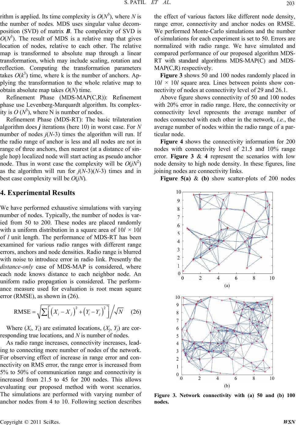 S. PATIL ET AL. 203 rithm is applied. Its time complexity is O(N3), where N is the number of nodes. MDS uses singular value decom- position (SVD) of matrix B. The complexity of SVD is O(N3). The result of MDS is a relative map that gives location of nodes, relative to each other. The relative map is transformed to absolute map through a linear transformation, which may include scaling, rotation and reflection. Computing the transformation parameters takes O(k3) time, where k is the number of anchors. Ap- plying the transformation to the whole relative map to obtain absolute map takes O(N) time. Refinement Phase (MDS-MAP(C,R)): Refinement phase use Levenberg-Marquardt algorithm. Its complex- ity is O (N3), where N is number of nodes. Refinement Phase (MDS-RT): The basic trilateration algorithm does j iterations (here 10) in worst case. For N number of nodes j(N-3) times the algorithm will run. If the radio range of anchor is less and all nodes are not in range of three anchors, then nearest (at a distance of sin- gle hop) localized node will start acting as pseudo anchor node. Thus in worst case the complexity will be O(jN2) as the algorithm will run for j(N-3)(N-3) times and in best case complexity will be O(jN). 4. Experimental Results We have performed exhaustive simulations with varying number of nodes. Typically, the number of nodes is var- ied from 50 to 200. These nodes are placed randomly with a uniform distribution in a square area of 10l × 10l of l unit length. The performance of MDS-RT has been examined for various radio ranges with different range errors, anchors and node densities. Radio range is blurred with noise to introduce error in radio link. Presently the distance-only case of MDS-MAP is considered, where each node knows distance to each neighbor node. An uniform radio propagation is considered. The perform- ance measure used for evaluation is root mean square error (RMSE), as shown in (26). 22 RMSE ij ij XYY N (26) Where (Xi, Yi) are estimated locations, (Xj, Yj) are cor- responding true locations, and N is number of nodes. As radio range increases, connectivity increases, lead- ing to connecting more number of nodes of the network. For observing effect of increase in range error and con- nectivity on RMS error, the range error is increased from 5% to 50% of communication range and connectivity is increased from 21.5 to 45 for 200 nodes. This allows evaluating our proposed method with worst scenarios. The simulations are performed with varying number of anchor nodes from 4 to 10. Following section describes the effect of various factors like different node density, range error, connectivity and anchor nodes on RMSE. We performed Monte-Carlo simulations and the number of simulations for each experiment is set to 50. Errors are normalized with radio range. We have simulated and compared performance of our proposed algorithm MDS- RT with standard algorithms MDS-MAP(C) and MDS- MAP(C,R) respectively. Figure 3 shows 50 and 100 nodes randomly placed in 10l × 10l square area. Lines between points show con- nectivity of nodes at connectivity level of 29 and 26.1. Above figure shows connectivity of 50 and 100 nodes with 20% error in radio range. Here, the connectivity or connectivity level represents the average number of nodes connected with each other in the network, i.e., the average number of nodes within the radio range of a par- ticular node. Figure 4 shows the connectivity information for 200 nodes with connectivity level of 21.5 and 10% range error. Figure 3 & 4 represent the scenarios with low node density to high node density. In these figures, line joining nodes are connectivity links. Figure 5(a) & (b) show scatter-plots of 200 nodes (a) (b) Figure 3. Network connectivity with (a) 50 and (b) 100 nodes. Copyright © 2011 SciRes. WSN 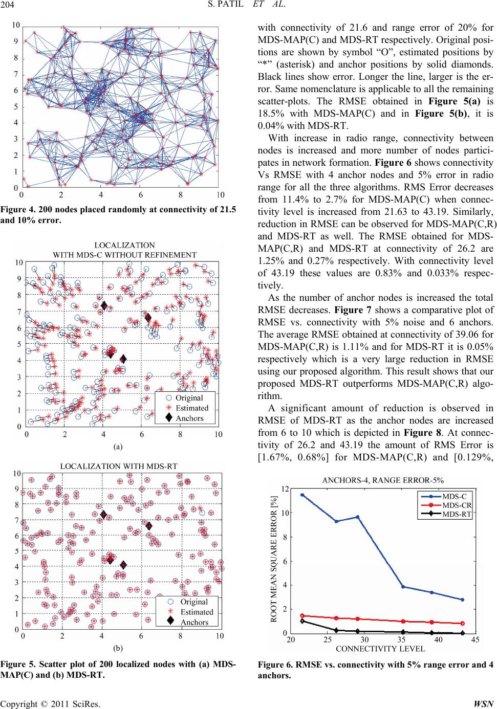 204 S. PATIL ET AL. Figure 4. 200 nodes placed randomly at connectivity of 21.5 and 10% error. (a) (b) Figure 5. Scatter plot of 200 localized nodes with (a) MDS- MAP(C) and (b) MDS-RT. with connectivity of 21.6 and range error of 20% for MDS-MAP(C) and MDS-RT respectively. Original posi- tions are shown by symbol “O”, estimated positions by “*” (asterisk) and anchor positions by solid diamonds. Black lines show error. Longer the line, larger is the er- ror. Same nomenclature is applicable to all the remaining scatter-plots. The RMSE obtained in Figure 5(a) is 18.5% with MDS-MAP(C) and in Figure 5(b), it is 0.04% with MDS-RT. With increase in radio range, connectivity between nodes is increased and more number of nodes partici- pates in network formation. Figure 6 shows connectivity Vs RMSE with 4 anchor nodes and 5% error in radio range for all the three algorithms. RMS Error decreases from 11.4% to 2.7% for MDS-MAP(C) when connec- tivity level is increased from 21.63 to 43.19. Similarly, reduction in RMSE can be observed for MDS-MAP(C,R) and MDS-RT as well. The RMSE obtained for MDS- MAP(C,R) and MDS-RT at connectivity of 26.2 are 1.25% and 0.27% respectively. With connectivity level of 43.19 these values are 0.83% and 0.033% respec- tively. As the number of anchor nodes is increased the total RMSE decreases. Figure 7 shows a comparative plot of RMSE vs. connectivity with 5% noise and 6 anchors. The average RMSE obtained at connectivity of 39.06 for MDS-MAP(C,R) is 1.11% and for MDS-RT it is 0.05% respectively which is a very large reduction in RMSE using our proposed algorithm. This result shows that our proposed MDS-RT outperforms MDS-MAP(C,R) algo- rithm. A significant amount of reduction is observed in RMSE of MDS-RT as the anchor nodes are increased from 6 to 10 which is depicted in Figure 8. At connec- tivity of 26.2 and 43.19 the amount of RMS Error is [1.67%, 0.68%] for MDS-MAP(C,R) and [0.129%, Figure 6. RMSE vs. connectivity with 5% range error and 4 anchors. Copyright © 2011 SciRes. WSN  S. PATIL ET AL. 205 Figure 7. RMSE vs. connectivity with 5% error and 6 an- chors. Figure 8. RMSE vs. connectivity level with 5% range error and 10 anchors. 0.0002%] for MDS-RT respectively. Thus the accuracy increases by about 45% for connectivity of 43.19. The efficiency and excellent performance of the pro- posed algorithm is very much evident from these graphs. Specifically when number of anchor nodes is 10, RMS error obtained is negligible and it is shown as zero here. When simulations were performed for 10% range error, RMSE obtained at connectivity of 21.6 is 4.2e-04, and as the radio range goes on increasing, the error goes on de- creasing. At connectivity level of 45, error is reduced to 2.1e-05. Next, we will analyze performance of algorithm in presence of various levels of noise. It is obvious that with increase in noise level, RMSE will also increase. The comparative plot of effect of increase in range error on RMSE using all three methods is shown in Figure 9. It is obtained at connectivity level of 29.1 with 6 anchors. Figure 9. Effect of increase in rage error on RMSE. When the range error is increased from 5% to 50% (worst scenario), the RMSE increases from 3.9% to 8.1% for MDS-MAP(C), 0.87% to 4.45% for MDS-MAP(C,R) and 0.067% to 2.35% for MDS-RT respectively. With increase in the number of anchors, the location estimate is more accurate and reduction in RMSE is ob- served. When range error is increased to 10% the effect on RMSE is seen as shown in Figure 11. Comparing Fig- ures 10 and 11, it can be observed that, the RMSE of MDS-MAP(C) increases to 9.6% from 9.2%, when error increases from 5% to 10% with 4 anchors. With MDS-MAP(C,R), RMSE increases from 1.3% to 1.5%, and with MDS-RT it increases from 0.4% to 0.7% re- spectively. With 10 anchors, RMSE of MDS-RT increa- ses from 0.028% to 0.038% whereas MDS-MAP(C,R) increases from 0.5% to 0.9% respectively. Table 1 shows the performance of all three algorithms with 4, 6, and 10 anchors. The data shows the effect on RMSE with 5% and 10% range error at connectivity of Figure 10. Effect of increase in number of anchors on RMSE with 5% range error. Copyright © 2011 SciRes. WSN  206 S. PATIL ET AL. Figure 11. Effect of increase in number of anchors on RMSE with 10% range error. Table 1. Performance comparison at connectivity of 26.2. Range Error (%) RMSE(%) MDS-MAP(C) 4 Anchors 5 9.2 10 9.54 6 Anchors 5 5.3 10 7.3 10 Anchors 5 3.5 10 3.7 MDS-MAP(C,R) 4 Anchors 5 1.25 10 1.8 6 Anchors 5 0.9 10 1.35 10 Anchors 5 0.6 10 0.83 MDS_RT 4 Anchors 5 0.26 10 1.01 6 Anchors 5 0.21 10 0.83 10 Anchors 5 0.023 10 0.031 26.2. The RMSE is normalized to radio range and per- centage error is computed. As it is clear from above figures and Table 1, our proposed method performs better than MDS-MAP(C,R). As can be seen from Figure 11, the error approaches nearly to zero even in the case of 10% range error. The remarkable difference is seen when number of anchor nodes are high i.e. > 5 and connectivity > 26.1. We have also performed the simulation of placing an- chor nodes colinearly for 50, 100 and 200 nodes. Place- ment of anchors plays a very important role in any local- ization algorithm. This is very important to note that the trilateration method fails, if anchor nodes are collinearly located. The proposed algorithm MDS-RT overcomes this problem. As MDS provides good initial estimate of locations, even though the anchor nodes are collinearly located, trilateration refines the estimated locations only. If anchors are not in radio range of each other or non-anchor nodes are not in the range of anchor nodes then algorithm may give erroneous results. However, this problem can be overcome with dense network topology. Figure 12 shows the localization using MDS-MAP(C) and MDS-RT for 50 nodes when nodes are placed colin- early. At connectivity of 21.6, with 20% range error and 4 number of anchor nodes, the RMS Error is 50% for MDS-MAP(C) and 15% for MDS-RT. As the density of nodes increases, with less radio range also nodes start communicating as they get enough connectivity. Figure 13 and 14 show simulation for 100 and 200 nodes with 20% range error. At connectivity of 26.1 with range error of 20%, RMSE obtained is 37% and 0.2% for MDS-MAP(C) and MDS-RT respectively for 200 nodes. From all the graphs and scatter-plots, it is clear that our proposed algorithm MDS-RT outperforms MDS- MAP(C,R) algorithm. If accuracy is not to be compro- (a) (b) Figure 12. (a)(b): Scatter plot of 50 nodes for MDS-MAP(C), and MDS-RT. Copyright © 2011 SciRes. WSN 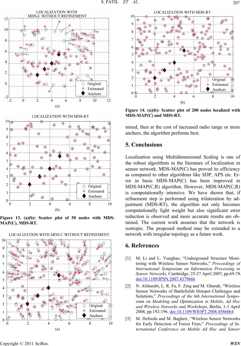 S. PATIL ET AL. 207 (a) (b) Figure 13. (a)(b): Scatter plot of 50 nodes with MDS- MAP(C), MDS-RT. (a) (b) Figure 14. (a)(b): Scatter plot of 200 nodes localized with MDS-MAP(C) and MDS-RT. mised, then at the cost of increased radio range or more anchors, the algorithm performs best. 5. Conclusions Localization using Multidimensional Scaling is one of the robust algorithms in the literature of localization in sensor network. MDS-MAP(C) has proved its efficiency as compared to other algorithms like SDP, APS etc. Er- ror in basic MDS-MAP(C) has been improved in MDS-MAP(C,R) algorithm. However, MDS-MAP(C,R) is computationally intensive. We have shown that, if refinement step is performed using trilateration by ad- justment (MDS-RT), the algorithm not only becomes computationally light weight but also significant error reduction is observed and more accurate results are ob- tained. The current work assumes that the network is isotropic. The proposed method may be extended to a network with irregular topology as a future work. 6. References [1] M. Li and L. Yunghao, “Underground Structure Moni- toring with Wireless Sensor Networks,” Proceedings of International Symposium on Information Processing in Sensor Networks, Cambridge, 25-27 April 2007, pp.69-78. doi:10.1109/IPSN.2007.4379666 [2] N. Alsharabi, L. R. Fa, F. Zing and M. Ghurab, “Wireless Sensor Networks of Battlefields Hotspot Challenges and Solutions,” Proceedings of the 6th International Sympo- sium on Modeling and Optimization in Mobile, Ad Hoc and Wireless Networks and Workshops, Berlin, 1-3 April 2008, pp.192-196. doi:10.1109/WIOPT.2008.4586064 [3] M. Hefeeda and M. Bagheri, “Wireless Sensor Networks for Early Detection of Forest Fires,” Proceedings of In- ternational Conference on Mobile Ad Hoc and Sensor Copyright © 2011 SciRes. WSN  S. PATIL ET AL. Copyright © 2011 SciRes. WSN 208 Systems, Pisa, 8-11 October 2007, pp. 1-6. doi:10.1109/MOBHOC.2007.4428702 [4] N. Bulusu, J. Heidemann and D. Estrin, “GPS-Less Low Cost Outdoor Localization for Very Small Devices,” IEEE Transactions on Personal Communication, Vol. 7, No. 5, 2002, pp. 28-34. [5] M. Chu, H. Haussecker and F. Zhao, “Scalable Informa- tion-Driven Sensor Querying and Routing for Ad Hoc Heterogeneous Sensor Networks,” International Journal of High Performance Computing Applications, Vol. 16, No. 3, 2002, pp. 1-22. doi:10.1177/10943420020160030901 [6] B. Karp and H. T. Kung, “GPSR: Greedy Perimeter Stateless Routing for Wireless Networks,” Proceedings of the 6th International Conference on Mobile Computing and Networks (ACM Mobicom), 2000, pp.1-10. [7] Y. Yu, R. Govindan and D. Estrin, “Geographical and Energy Aware Routing: A Recursive Data Dissemination Protocol for Wireless Sensor Networks,” University of California, Los Angeles Computer Science Department Technical Report UCLA/CSD-TR-01-0023, May 2001. http://citeseerx.ist.psu.edu [8] Z. Guo and M. C. Zhou, “Optimal Tracking Interval for Predictive Tracking in Wireless Sensor Network,” IEEE Communication Letters, Vol. 9, No. 9, 2005, pp. 805-807. doi:10.1109/LCOMM.2005.1506709 [9] Y. Shang, W. Ruml, Y. Zhang and M. Fromherz, “Local- ization from Mere Connectivity,” The 4th ACM Interna- tional Symposium on Mobile and Ad-Hoc Networking & Computing Symposium on Mobile and Ad-Hoc Network- ing & Computing, 2003, pp. 201-212. [10] I. Borg and P. Groenen, “Modern Multidimensional Scaling, Theory and Applications,” Springer, New York, 1997. [11] W. S. Torgeson, “Multidimensional Scaling of Similar- ity,” Psychometrika, Vol. 30, No. 4, 1965, pp. 379-393. doi:10.1007/BF02289530 [12] R. N. Shepard, “The Analysis of Proximities: Multidi- mensional Scaling with an Unknown Distance Function,” Psychometrika, Vol. 27, No. 2, 1962, pp. 125-140. doi:10.1007/BF02289630 [13] Y. Shang, W Ruml, Y. Zhang and M. Fromherz, “Local- ization from Connectivity in Sensor Networks,” IEEE Transactions on Parallel and Distributed Systems, Vol. 15, No. 11, 2004, pp. 961-974. doi:10.1109/TPDS.2004.67 [14] T. Hornoch, “Notes on the Adjustment of Trilateration,” Survey Review, Vol. 18, No. 135, 1965, pp. 14-18. [15] G. Q. Mao, B. Fidan and B. D. O. Anderson, “Wireless sensor Network Localization Techniques,” The Interna- tional Journal of Computer and Telecommunications Networking Computer Networks, Vol. 51, No. 10, 2007, pp. 2529-2553. [16] I. F. Akyildiz, W. Su, Y. Sankarasubramaniam and E. Cayirci, “A Survey on Sensor Networks,” Computer Networks, Vol. 40, No. 8, 2002, pp. 393-422. doi:10.1016/S1389-1286(01)00302-4 [17] X. Li, H. Shi and Y. Shang, “A Sorted RSSI Quantization Based Algorithm for Sensor Network Localization,” Proceedings of 11th International Conference on Parallel and Distributed Systems, 20-22 July 2005, pp. 557-563. [18] P. Xing, H. Yu and Y. Zhang, “An Assisting Localization Method for Wireless Sensor Networks,” Proceedings of the Second International Conference on Mobile Tech- nology, Applications and Systems, Guangzhou, 15-17 November 2005, pp. 1-6. [19] T. He, C. Huang, B. Blum, J. Stankovic and T. Abdelza- her, “Range-Free Localization Schemes for Large Scale Sensor Networks,” Proceedings of the Ninth Annual In- ternational Conference on Mobile Computing and Net- working (ACM Mobicom), San Diego, September 2003, pp. 81-95. [20] D. Niculescu and B. Nath, “Ad Hoc Positioning System,” Proceedings of the Global Telecommunications Confer- ence, San Antonio, 25-29 November 2001, pp. 2926- 2931. [21] C. Savarese, J. Rabay and K. Langendoen, “Robust Posi- tioning Algorithms for Distributed Ad-Hoc Wireless Sensor Networks,” USENIX Technical Annual Confer- ence, June 2002, pp. 1-10. [22] A. Savvides, C. Han and M. B. Srivastava, “Dynamic Fine-Grained Localization in Ad-Hoc Networks of Sen- sors,” Proceedings of the 7th Annual International Con- ference on Mobile Computing and Networking (ACM Mobicom), 2001, pp. 166-179. [23] F. Tian, W. Guo, C. Wang and Q. Gao, “Robust Local- ization Based on Adjustment of Trilateration Network for Wireless Sensor Networks,” Proceedings of 4th Interna- tional Conference on Wireless Communications, Network- ing and Mobile Computing, 12-14 October 2008, pp. 1-4. [24] A. Savvides, H. Park and M. B. Srivastava, “The Bits and Flops of the N-Hop Multilateration Primitive for Node Localization Problems,” Proceedings of the 1st ACM In- ternational Workshop on Wireless Sensor Networks and Applications, Atlanta, 8 September 2002, pp. 112-121. [25] L. Doherty, K. pister and L. El. Ghaoui, “Convex Posi- tion Estimation in Wireless Sensor Networks,” Proceed- ings of the Twentieth Annual Joint Conference of the IEEE Computer and Communications Societies, Ancho- rage, 22-26 April 2001, pp. 1655-1663. [26] P. Biswas and Y. Ye, “Semidefinite Programming for Ad Hoc Wireless Sensor Network Localization,” Proceed- ings of the Third International Symposium on Information Processing in Sensor Network, new York, 26-27 April 2004, pp. 46-54. doi:10.1145/984622.984630 [27] T. C. Liang, T. C. Wang and Y. Ye, “A Gradient Search Method to Round the Semidefinite Programming Relaxa- tion Solution for Ad Hoc Wireless Sensor Network Lo- calization,” Stanford University, Formal Report 5, 2004. http://www.stanford. edu/-yyye/ formal-report5. pdf [28] B. Borchers, “CSDP-A C Library for Semidefinite Pro- gramming,” Optimization Methods and Software, Vol. 11, No. 1, 1999, pp. 613-623. doi:10.1080/10556789908805765
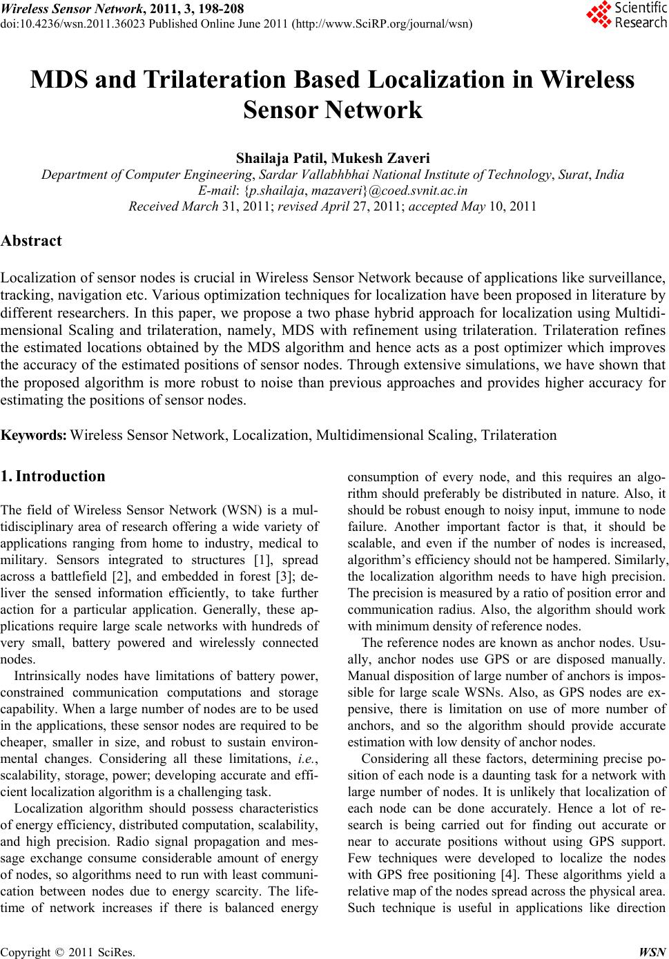
|