Paper Menu >>
Journal Menu >>
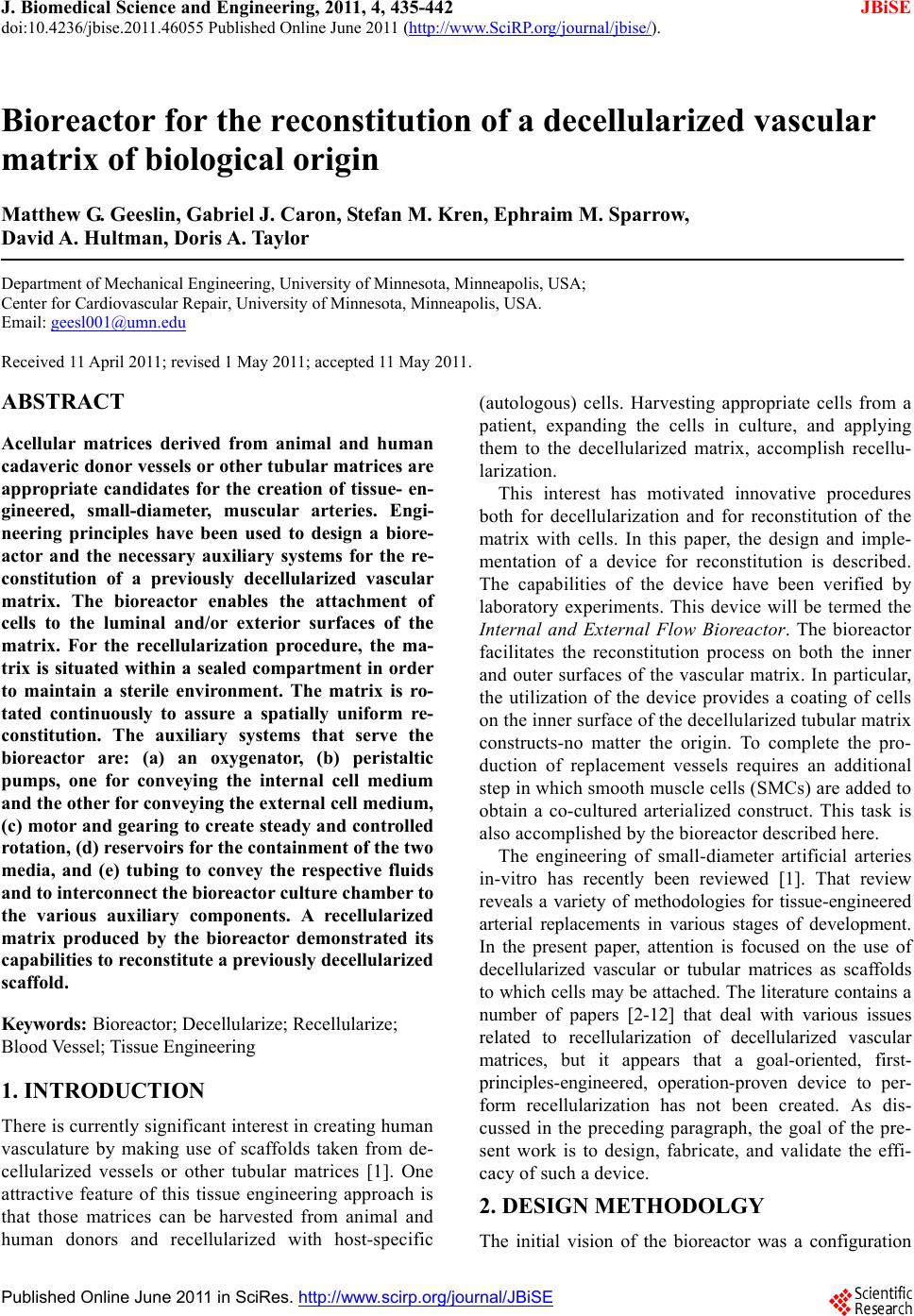 J. Biomedical Science and Engineering, 2011, 4, 435-442 JBiSE doi:10.4236/jbise.2011.46055 Published Online June 2011 (http://www.SciRP.org/journal/jbise/). Published Online June 2011 in SciRes. http://www.scirp.org/journal/JBiSE Bioreactor for the reconstitution of a decellularized vascular matrix of biological origin Matthew G. Geeslin, Gabriel J. Caron, Stefan M. Kren, Ephraim M. Sparrow, David A. Hultman, Doris A. Taylor Department of Mechanical Engineering, University of Minnesota, Minneapolis, USA; Center for Cardiovascular Repair, University of Minnesota, Minneapolis, USA. Email: geesl001@umn.edu Received 11 April 2011; revised 1 May 2011; accepted 11 May 2011. ABSTRACT Acellular matrices derived from animal and human cadaveric donor vessels or other tubular matrices are appropriate candidates for the creation of tissue- en- gineered, small-diameter, muscular arteries. Engi- neering principles have been used to design a biore- actor and the necessary auxiliary systems for the re- constitution of a previously decellularized vascular matrix. The bioreactor enables the attachment of cells to the luminal and/or exterior surfaces of the matrix. For the recellularization procedure, the ma- trix is situated within a sealed compartment in order to maintain a sterile environment. The matrix is ro- tated continuously to assure a spatially uniform re- constitution. The auxiliary systems that serve the bioreactor are: (a) an oxygenator, (b) peristaltic pumps, one for conveying the internal cell medium and the other for conveying the external cell medium, (c) motor and gearing to create steady and controlled rotation, (d) reservoirs for the containment of the two media, and (e) tubing to convey the respective fluids and to interconnect the bioreactor culture chamber to the various auxiliary components. A recellularized matrix produced by the bioreactor demonstrated its capabilities to reconstitute a previously decellularized scaffold. Keywords: Bioreactor; Decellularize; Recellularize; Blood Vessel; Tissue Engineering 1. INTRODUCTION There is curren tly signific ant interest in crea ting human vasculature by making use of scaffolds taken from de- cellularized vessels or other tubular matrices [1]. One attractive feature of this tissue engineering approach is that those matrices can be harvested from animal and human donors and recellularized with host-specific (autologous) cells. Harvesting appropriate cells from a patient, expanding the cells in culture, and applying them to the decellularized matrix, accomplish recellu- larization. This interest has motivated innovative procedures both for decellularization and for reconstitution of the matrix with cells. In this paper, the design and imple- mentation of a device for reconstitution is described. The capabilities of the device have been verified by laboratory experiments. This device will be termed the Internal and External Flow Bioreactor. The bioreactor facilitates the reconstitution process on both the inner and outer surfaces of the vascular matrix. In particular, the utilization of the device provides a coating of cells on the inn er surf ace of the dec ellu lar ized tu bul ar matr ix constructs-no matter the origin. To complete the pro- duction of replacement vessels requires an additional step in which smooth muscle cells (SMCs) are added to obtain a co-cultured arterialized construct. This task is also accomplished by the bioreactor described here. The engineering of small-diameter artificial arteries in-vitro has recently been reviewed [1]. That review reveals a variety of methodologies for tissue-engineered arterial replacements in various stages of development. In the present paper, attention is focused on the use of decellularized vascular or tubular matrices as scaffolds to which cells may be attach ed. The literature contains a number of papers [2-12] that deal with various issues related to recellularization of decellularized vascular matrices, but it appears that a goal-oriented, first- principles-engineered, operation-proven device to per- form recellularization has not been created. As dis- cussed in the preceding paragraph, the goal of the pre- sent work is to design, fabricate, and validate the effi- cacy of such a device. 2. DESIGN METHODOLGY The initial vision of the bioreactor was a configuration  M. G. Geeslin et al. / J. Biomedical Science and Engineering 4 (2011) 435-442 Copyright © 2011 SciRes. JBiSE 436 which would enable a continuous flow of tissue-culture medium both within the lumen of the decellularized ma- trix and over its external surface. That vision also in- cluded the idea of matrix rotation to ensure the spatial uniformity of the final cellular deposition. The minimum requirements that were specified at the initiation of the design pr oc e ss included: a) Continuous, automated, and low-RPM matrix rota- tion; b) Closed-loop, operator-controlled perfusion of both the lumen and the external surface of the vascular matrix; c) Leakage-free interfaces which enforce the mainte- nance of a sterile environment within the processing chamber; d) Sterilizability of device components that interact with biological products. The need for Requirement A is to increase the likeli- hood of confluent distribution of the endothelial cells (ECs) in the lumen and smooth muscle cells on the outer surface of the vascular matrix. Requirement B was mo- tivated by the desire to separate and separately control perfusion of the interior and exterior of the matrix to fulfill the goal of depositing potentially different cell types on the interior and exterior surfaces in recognition of different biological needs. Requirements C and D, taken together, provide for the sterility of the culture environment. 3. DEVICE OVERVIEW The description of the device will be subdivided into two main sections. The first will convey a schematic of the overall system; describe its functio nality, and its mode of operation. Subsequently, a number of photographs will be displayed to illu strate the practical implementation of the device. The device schematic is displayed in Figure 1. The figure is a schematic flow diagram of the internal and external flow bioreactor. The heart of the device is the bioreactor culture chamber. It is a cylindrical vessel having a diameter and leng th of about 25mm and 75 mm, respectively, with its axis horizontal. It is made of trans- parent polycarbonate. The function of the culture cham- ber is to provide a sterile environment in which a decel- lularized tubular matrix is supported at its ends. The ma- trix is separately perfused bo th internally and externally. Internal perfusion is accomplished by connecting the respective ends of the matrix to the cell-culture-medium supply and extraction ports that are respectively located at either end of the bioreactor. External perfusion is ac- complished via ports into and out of the bioreactor cul- ture chamber. It can be seen from the figure that the two flow cir- cuits are independent and have their own auxiliaries. One of the auxiliaries is an autoclavable cell-culture flask that is sealed by a rubber stopper equipped with inlet and outlet ports. A second is a peristaltic pump that is situated downstream of the flask. The pump is able to provide flow-rates between 0.06 mL/min and 43 mL/min. The discharge of the pump is delivered to the pressur- ized oxygenator, the third auxiliary, whose function is to maintain the oxygen content to replace that lost in cellu- lar respiration. A key feature of the bioreactor is the capability to ro- tate the vascular matrix simultaneously with its perfu- sion. The RPM of the rotation is adjustable from one to three revolutions per minute. The rotational components Figure 1. Schematic flow diagram of the bioreactor and its auxiliary components.  M. G. Geeslin et al. / J. Biomedical Science and Engineering 4 (2011) 435-442 Copyright © 2011 SciRes. JBiSE 437 include not only the vascular matrix, but also the ma- trix support members to which the matrix is attached. Rotation is achieved by means of a low-RPM DC motor. The external shell of the bioreactor does not rotate. Figure 2 illustrates the key components of the device. As can be seen in the figure, the underlying structure of the device is made of a plastic, and Delrin was chosen because of machinability and autoclavability. The bioreactor culture chamber is seen to be the central feature of the device. Provision was allowed in the structure for a drive shaft which extended from the proximal and distal ends of the device. The shaft was driven by a motor situated at the distal end. By means of a pair of gears which mate with the driveshaft, rotation is imparted to the matrix and its supporting structures. The entire assembly is laid out on a 6.25-mm-thick aluminum plate. Figure 3 is a downward-directed view of the fabricated device in its operational environment. The setup of the device is specific to the perfusion of the lumen. Therefore, the exhibited components relate to that mode Figure 2. Overall view of the fabricated device displaying certain key components. Figure 3. Downward directed overview of the fabricated device in its operational envi- ronment illustrating lumenal perfusion.  M. G. Geeslin et al. / J. Biomedical Science and Engineering 4 (2011) 435-442 Copyright © 2011 SciRes. JBiSE 438 of operation. The fully assembled device perfuses both the interior and exterior surfaces of the vascular matrix. The identification labels show the oxygenator, the culture medium flask, and the drive motor. Also seen in the photograph are the front and rear drive gears for rotation. 4. DEVICE DETAILS The design of the bioreactor includes a number of fea- tures that guarantee its proper operation. These design details will now be displayed. Figure 4 displays the bioreactor culture vessel in more detail than could be observed in the preceding overview figures. The figure shows the reactor to consist of a transparent cylindrical vessel within which certain critical fixtures are contained. One of these fixtures is the pair of vascular matrix support members. The origins of these structures are syringes of suitable size. The inflow and outflow ports used to perfuse the exterior surface of the vascular matrix are clearly shown in this photograph. Other features that are somewhat obscured in Figure 4 will be called out in later figures where they are more easily identified. A dissassembled view of the bioreactor and its components is presented in Figure 5. Shown there are the parts of the parent syringes th at were utilized for the support of the matrix and for the delivery and extraction for the perfusing fluid. The matrix support structure is seen to consist of a barrel-like disc at either end and a bridging structure that interconnects them. A critical Figure 4. Detail of the bioreactor culture vessel. Figure 5. Disassembled view of the bioreactor culture vessel. 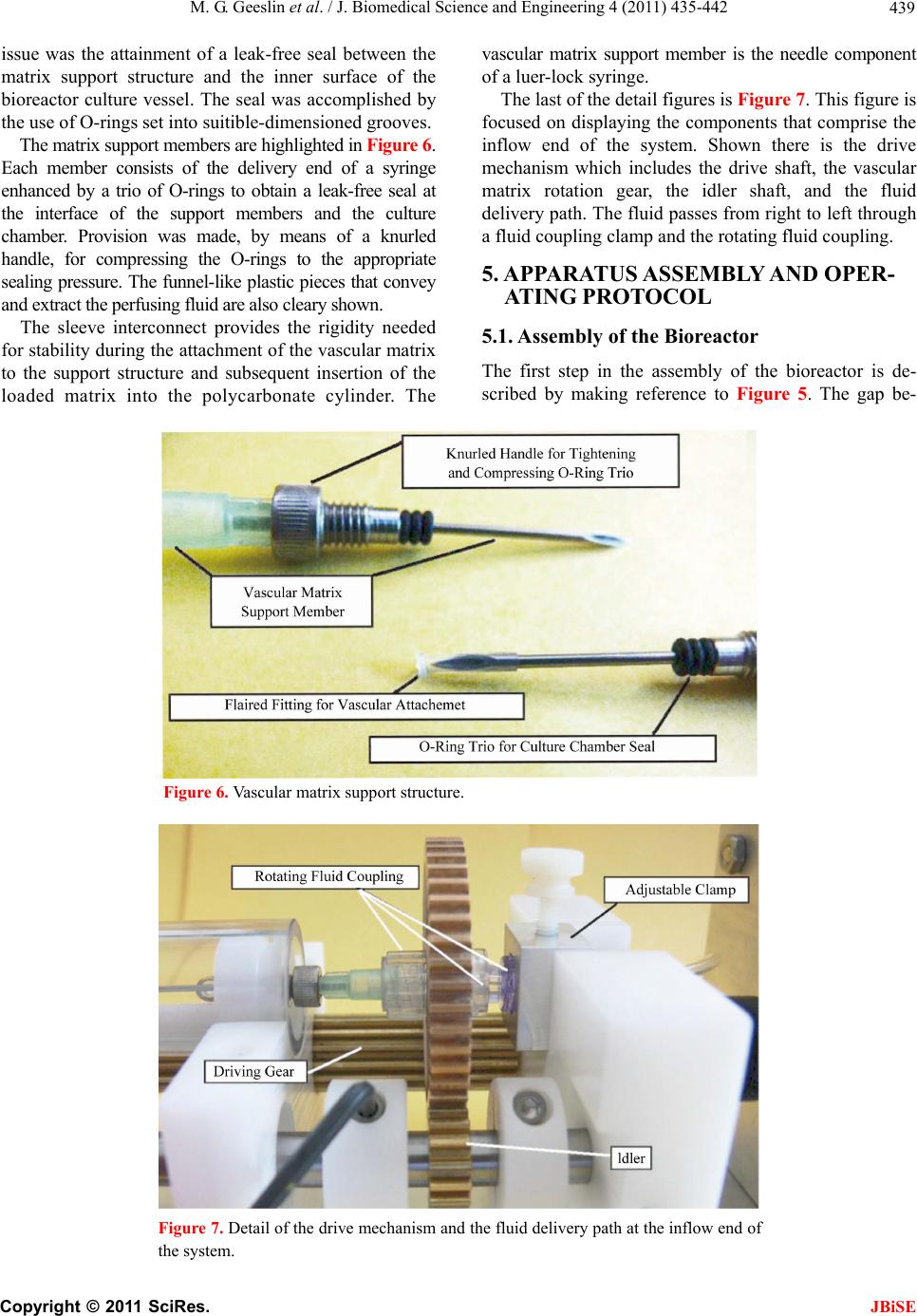 M. G. Geeslin et al. / J. Biomedical Science and Engineering 4 (2011) 435-442 Copyright © 2011 SciRes. JBiSE 439 issue was the attainment of a leak-free seal between the matrix support structure and the inner surface of the bioreactor culture vessel. The seal was accomplished by the use of O-rings set into suitible-dimensioned grooves. The matrix support members are highlighted in Figur e 6. Each member consists of the delivery end of a syringe enhanced by a trio of O-rings to obtain a leak-free seal at the interface of the support members and the culture chamber. Provision was made, by means of a knurled handle, for compressing the O-rings to the appropriate sealing pressure. The funnel-like plastic pieces that convey and extract the perfusi ng fluid are als o cleary shown. The sleeve interconnect provides the rigidity needed for stability during the attachment o f the vascular matrix to the support structure and subsequent insertion of the loaded matrix into the polycarbonate cylinder. The vascular matrix support member is the needle component of a luer-lock syringe. The last of the detail figures is Figure 7. This figure is focused on displaying the components that comprise the inflow end of the system. Shown there is the drive mechanism which includes the drive shaft, the vascular matrix rotation gear, the idler shaft, and the fluid delivery path. The fluid passes from right to left through a fluid coupling clamp and the rotating fluid coupling. 5. APP ARATUS ASSEMBLY AND OPER- ATING PROTOCOL 5.1. Assembly of the Bioreactor The first step in the assembly of the bioreactor is de- scribed by making reference to Figure 5. The gap be- Figure 6. Vascular matrix support structure. Figure 7. Detail of the drive mechanism and the fluid delivery path at the inflow end of the system. 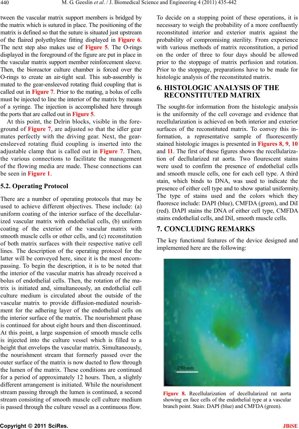 M. G. Geeslin et al. / J. Biomedical Science and Engineering 4 (2011) 435-442 Copyright © 2011 SciRes. JBiSE 440 tween the vascular matrix support members is bridged by the matrix which is sutured in place. The positioning of the matrix is defined so that the suture is situated just upstream of the flaired polyethylene fitting displayed in Figure 6. The next step also makes use of Figure 5. The O-rings displayed in the foreground of the figure are put in place in the vascular matrix support member reinforcement sleeve. Then, the bioreactor culture chamber is forced over the O-rings to create an air-tight seal. This sub-assembly is mated to the gear-ensleeved rotating fluid coupling that is called out in Figure 7. Prior to the mating, a bolus of cells must b e inj ec ted to lin e th e int erior o f the mat rix by me ans of a syringe. The injection is accomplished here through the ports that are called out in Figure 5. At this point, the Delrin blocks, visible in the fore- ground of Figure 7, are adjusted so that the idler gear mates perfectly with the driving gear. Next, the gear- ensleeved rotating fluid coupling is inserted into the adjustable clamp that is called out in Figure 7. Then, the various connections to facilitate the management of the flowing media are made. These connections can be seen in Figure 1. 5.2. Operating Protocol There are a number of operating protocols that may be used to achieve different objectives. These include: (a) uniform coating of the interior surface of the decellular- ized vascular matrix with endothelial cells, (b) uniform coating of the exterior of the vascular matrix with smooth muscle cells or other cells, and (c) reconstitution of both matrix surfaces with their respective native cell lines. The description of the operating protocol for the latter will be conveyed here, since it is the most encom- passing. To begin the description, it is to be noted that the interior of the vascular matrix has already received a bolus of endothelial cells. Then, the rotation of the ma- trix is initiated and, simultaneously, an endothelial cell culture medium is circulated about the outside of the vascular matrix to provide diffusion-mediated nourish- ment for the adhering layer of the endothelial cells on the interior surface of the matrix. The nourishment phase is continued for about eigh t hours and then discon tinued. At this point, a large suspension of smooth muscle cells is injected into the culture vessel which is filled to a height that envelops the vascular matrix. Simultaneously, the nourishment stream that formerly passed over the outer surface of the matrix is now ducted to flo w through the lumen of the matrix. These conditions are continued for a period of approximately 12 hours. Then, a slightly different arrangement is initiated. While the nourish ment stream passing through the lumen is continued, a second stream consisting of smooth muscle cell culture medium is passed through the culture vessel as a continuous flow. To decide on a stopping point of these operations, it is necessary to weigh the probability o f a more confluently reconstituted interior and exterior matrix against the probability of compromising sterility. From experience with various methods of matrix reconstitution, a period on the order of three to four days should be allowed prior to the stoppage of matrix perfusion and rotation. Prior to the stoppage, preparations have to be made for histologic analysis of the reconstituted matrix. 6. HISTOLOGIC ANALYSIS OF THE RECONSTITUTED MATRIX The sought-for information from the histologic analysis is the uniformity of the cell coverage and evidence that recellularization is achieved on both interior and exterior surfaces of the reconstituted matrix. To convey this in- formation, a representative sample of fluorescently stained histologic images is presented in Figures 8, 9, 10 and 11. The first of these figures shows the recellulariza- tion of decllularized rat aorta. Two flourescent stains were used to confirm the presence of endothelial cells and smooth muscle cells, one for each cell type. A third stain, which binds to DNA, was used to indicate the presence of either cell type and to show spatial uniformity. The type of stains used and the colors which they fluoresce include: DAPI (blue), CMFDA (green), and DiI (red). DAPI stains the DNA of either cell type, CMFDA stains endothelial cel l s , and D i I, smooth m uscle cell s. 7. CONCLUDING REMARKS The key functional features of the device designed and implemented here are the following : Figure 8. Recellularization of decellularized rat aorta showing en face cells of the endothelial type at a vascular branch point. Stain: DAPI (blue) and CMFDA (green). 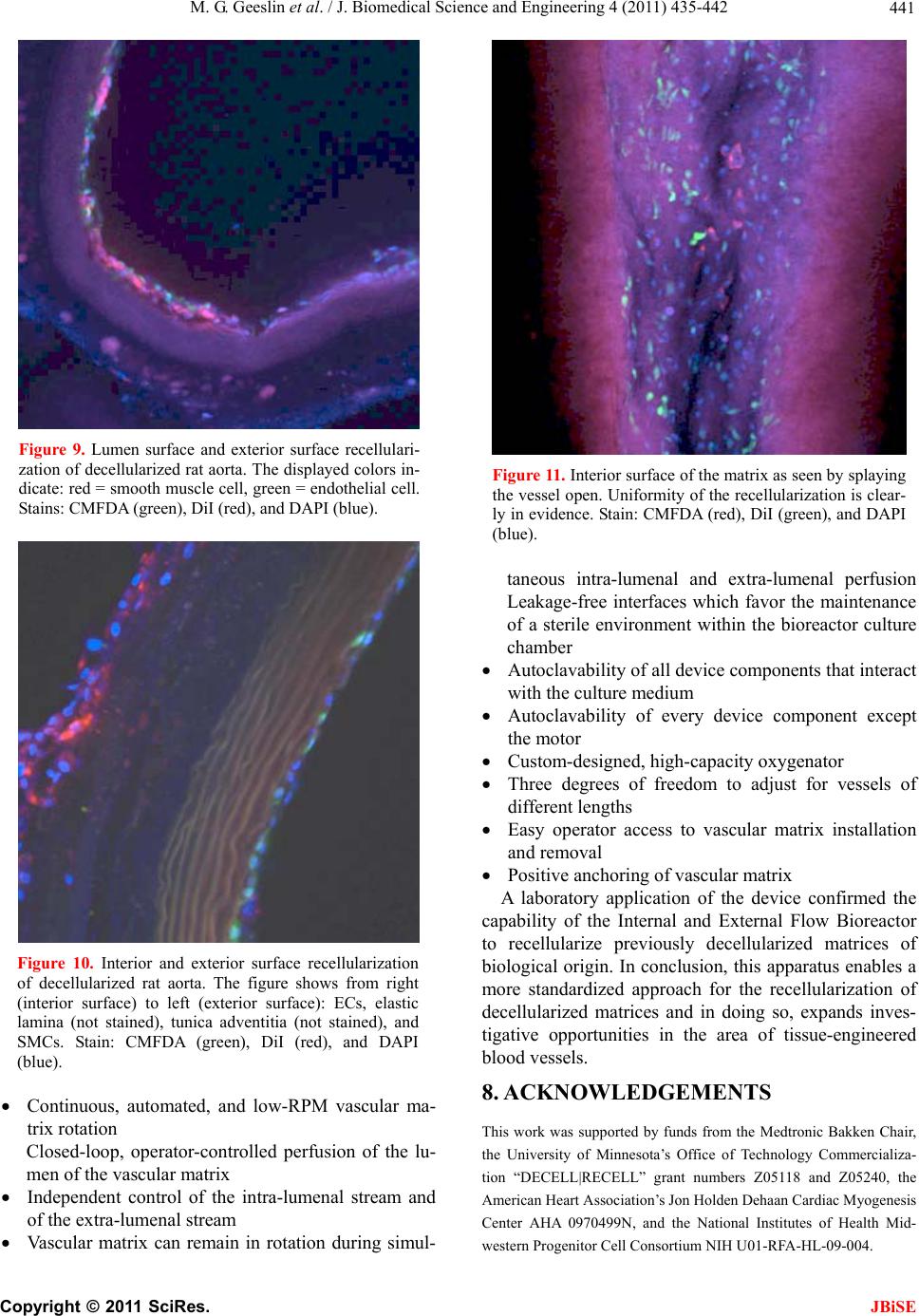 M. G. Geeslin et al. / J. Biomedical Science and Engineering 4 (2011) 435-442 Copyright © 2011 SciRes. JBiSE 441 Figure 9. Lumen surface and exterior surface recellulari- zation of decellularized rat aorta. The displayed colors in- dicate: red = smooth muscle cell, green = endothelial cell. Stains: CMFDA (green), DiI (red), and DAPI (blue). Figure 10. Interior and exterior surface recellularization of decellularized rat aorta. The figure shows from right (interior surface) to left (exterior surface): ECs, elastic lamina (not stained), tunica adventitia (not stained), and SMCs. Stain: CMFDA (green), DiI (red), and DAPI (blue). Continuous, automated, and low-RPM vascular ma- trix rotation Closed-loop, operator-controlled perfusion of the lu- men of the vascular matrix Independent control of the intra-lumenal stream and of the extra-lumenal stream Vascular matrix can remain in rotation during simul- Figure 11. Interior surface of the matrix as seen by splaying the vessel open. Uniformity of the recellularization is clear- ly in evidence. Stain: CMFDA (red), DiI (green), and DAPI (blue). taneous intra-lumenal and extra-lumenal perfusion Leakage-free interfaces which favor the maintenance of a sterile environment within the bioreactor culture chamber Autoclavability of all device components that interact with the culture medium Autoclavability of every device component except the motor Custom-desig n e d, hi g h -capacity oxygenato r Three degrees of freedom to adjust for vessels of different lengths Easy operator access to vascular matrix installation and removal Positive anchoring of vascular matrix A laboratory application of the device confirmed the capability of the Internal and External Flow Bioreactor to recellularize previously decellularized matrices of biological origin. In conclusion, this apparatus enables a more standardized approach for the recellularization of decellularized matrices and in doing so, expands inves- tigative opportunities in the area of tissue-engineered blood vessels. 8. ACKNOWLEDGEMENTS This work was supported by funds from the Medtronic Bakken Chair, the University of Minnesota’s Office of Technology Commercializa- tion “DECELL|RECELL” grant numbers Z05118 and Z05240, the American Heart Association’s Jon Holden Dehaan Cardiac Myogenesis Center AHA 0970499N, and the National Institutes of Health Mid- western Progenitor Cell Consortium NIH U01-RFA-HL-09-004. 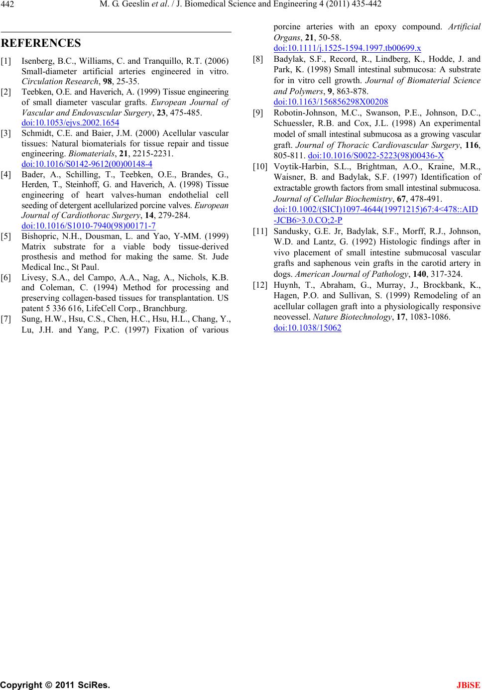 M. G. Geeslin et al. / J. Biomedical Science and Engineering 4 (2011) 435-442 Copyright © 2011 SciRes. JBiSE 442 REFERENCES [1] Isenberg, B.C., Williams, C. and Tranquillo, R.T. (2006) Small-diameter artificial arteries engineered in vitro. Circulation Research, 98, 25-35. [2] Teebken, O.E. and Haverich, A. (1999) Tissue en gineering of small diameter vascular grafts. European Journal of Vascular and Endovascular Surgery, 23, 475-485. doi:10.1053/ejvs.2002.1 654 [3] Schmidt, C.E. and Baier, J.M. (2000) Acellular vascular tissues: Natural biomaterials for tissue repair and tissue engineering. Biomaterials, 21, 2215-2231. doi:10.1016/S0142-9612 (00)00148-4 [4] Bader, A., Schilling, T., Teebken, O.E., Brandes, G., Herden, T., Steinhoff, G. and Haverich, A. (1998) Tissue engineering of heart valves-human endothelial cell seeding of detergent acellularized porcine valves. European Journal of Cardiothorac Surgery, 14, 279-284. doi:10.1016/S1010-7940(98)00171-7 [5] Bishopric, N.H., Dousman, L. and Yao, Y-MM. (1999) Matrix substrate for a viable body tissue-derived prosthesis and method for making the same. St. Jude Medical Inc., St Paul. [6] Livesy, S.A., del Campo, A.A., Nag, A., Nichols, K.B. and Coleman, C. (1994) Method for processing and preserving collagen-based tissues for transplantation. US patent 5 336 616, LifeCell Corp., Branchburg. [7] Sung, H.W., Hsu, C.S., Chen, H.C., Hsu, H.L., Chang, Y., Lu, J.H. and Yang, P.C. (1997) Fixation of various porcine arteries with an epoxy compound. Artificial Organs, 21, 50-58. doi:10.1111/j.1525-1594.1997.tb00699.x [8] Badylak, S.F., Record, R., Lindberg, K., Hodde, J. and Park, K. (1998) Small intestinal submucosa: A substrate for in vitro cell growth. Journal of Biomaterial Science and Polymers, 9, 863-878. doi:10.1163/156856298X00208 [9] Robotin-Johnson, M.C., Swanson, P.E., Johnson, D.C., Schuessler, R.B. and Cox, J.L. (1998) An experimental model of small intestinal submucosa as a growing vascular graft. Journal of Thoracic Cardiovascular Surgery, 116, 805-811. doi:10.1016/S0022-5223(98)00436-X [10] Voytik-Harbin, S.L., Brightman, A.O., Kraine, M.R., Waisner, B. and Badylak, S.F. (1997) Identification of extractable growth factors from small intestinal submucosa. Journal of Cellular Biochemistry, 67, 478-491. doi:10.1002/(SICI)1097-4644(19971215)67:4<478::AID -JCB6>3.0.CO;2-P [11] Sandusky, G.E. Jr, Badylak, S.F., Morff, R.J., Johnson, W.D. and Lantz, G. (1992) Histologic findings after in vivo placement of small intestine submucosal vascular grafts and saphenous vein grafts in the carotid artery in dogs. American Journal of Pathology, 140, 317-324. [12] Huynh, T., Abraham, G., Murray, J., Brockbank, K., Hagen, P.O. and Sullivan, S. (1999) Remodeling of an acellular collagen graft into a physiologically responsive neovessel. Nature Biotechnology, 17, 1083-1086. doi:10.1038/15062 |