Journal of Power and Energy Engineering, 2015, 3, 332-341
Published Online April 2015 in SciRes. http://www.scirp.org/journal/jpee
http://dx.doi.org/10.4236/jpee.2015.34045
How to cite this paper: Gong, Y., et al. (2015) Advanced Analysis of HVDC Electrodes Interference on Neighboring Pipelines.
Journal of Power and Energy Engineering, 3, 332-341. http://dx.doi.org/10.4236/jpee.2015.34045
Advanced Analysis of HVDC Electrodes
Interference on Neighboring Pipelines
Yu Gong1, Chunlin Xue2, Zhilei Yuan2, Yexu Li3, Farid Paul Dawalibi3
1China Southern Power Grid, Guangzhou, China
2Huadong Power Design Institute, Shanghai, China
3Safe Engineering Services & Technologies ltd., Laval, Quebec, Canada
Email: yexu.li@sestech.com, info@seschina.cn
Received February 2015
Abstract
This paper focuses on adv anc ed analysis techniques and design considerations of DC interference
generated by HVDC electr odes during normal bipolar and temporary monopolar operations on
neighboring metallic utilities, with a special emphasis on bur ied gas and oil pipelines. This study
examines the level of pipeline corr osi on, th e safety status in the vicinity of exposed appurtenances
and the impact of DC interference on the integrity of insulating flanges and impressed current ca-
thodic protection (ICCP) systems. Computation results obtained for different soil models show
that different soils can lead to completely different DC interference effects. The results and con-
clusions presented here can be used as a reference to analyze the severity of DC interference on
pipelines due to proximate HVDC electrodes .
Keywords
HVDC Electrode, DC Interference, P ipe-to-Soil Potential, Polarization Potential, Insulating Joint
(Flanges), Rectifier, Touch Voltage, Corrosion, Safety, Impressed Current Cathodic Protection
1. Introduction
HVDC networks have been widely implemented in China in recent years. HVDC has proved to be well suited to
specific applications, including long-distance power transmission, relatively long cable interconnections, inter-
connections between large isolated HVAC systems, and asynchronous tie-lines between HVAC systems. During
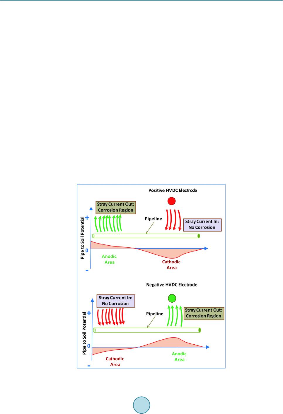
normal bipolar operations and particularly during temporary monopolar operations of the HVDC lines, DC cur-
rents injected into the soil result in an electric field that can introduc e excessive currents and voltages in nearby
metallic utilities, such as pipelines. Consequently, such current can cause or accelerate DC corrosion, damage
rectifiers and insulating flanges or joints and can threaten the safety of per s onne l working at valve and test sta-
tions as well as along the pipe. Due to the significant increase of HVDC systems, the con cerns on their possible
adverse impact on the environment have accelerated the need for accurate approaches to analyze HVDC adverse
effects on neighb ori ng buried metallic utilities and development of appropriate effective and economical mitiga-
tion measures.
This paper discusses recent advances and new developments achieved in the analysis of electromagnetic in-
Y. Gong et al.
333
terference generated by HVDC ground electrodes on neighboring metallic utilities, with a particular emphasis on
buried pipelines. This study is based on a realistic case and has been carried out using a computer model that re-
produces accurately the existing installations. The study includes comparisons between field measurements and
computed results in order to validate the computation method and computer models that were developed to de-
scribe accurately the existing system. It examines the level of pipeline corrosion, the safety status in the vicinity
of exposed appurtenances and the impact of DC interference on the integrity of insulating flanges and impressed
current cathodic protection (ICCP) systems. A future paper will deal with advanced mitigation measures to re-
duce the interference level to acceptable values following various design standards and criteria.
2. HVDC Electrode Interference Effects on Pipelines and Design Standards
HVDC systems may operate in such a manner that continuous (normal operation) or periodic (monopolar opera-
tion) direct current follows an earth path between HVDC system terminals. During such operations, a portion of
the DC current that is flowing between the two HVDC electrodes is captured by the pipelines and associated
grounding systems located in zones where the earth potentials are high and are discharged back to soil at loca-
tions where the earth potentials are lower. More precisely, a pipeline may collect, conduct, or discharge a por-
tion of this current depending on the location of the pipeline and the polarity of the HVDC ground electrode.
When the electrode near the pipeline is operating in positive mode, the current from the electrode is collected by
the pipeline in the region located in the vicinity of the electrode. The current is then discharged from the pipeline
at locations remote from the electrode; resulting in corrosion at these points. When the HVDC electrode near the
pipeline is operating in negative mode, the current is discharged from the pipeline in the vicinity of the electrode
and collected in the area far from the electrode. In this case, corrosion occurs near the electrode. In addition,
coating damage due to disbonding can also occur if the pipeline is polarized negatively b eyon d a safe level as a
result of excessive current collection. Figure 1 illustrates this DC interference mechanism due to the operation
of an HVDC electrode.
Figure 1. Mechanism of HVDC electrode interference.
Y. Gong et al.
334
The European Committee for Electrotechnical Standardization BS/EN50162-2004 [1] and Chinese National
Standard GB/T 21447-2008 [2] state that: 1) Protective measures must be applied if the pipe leakage current
densi ty is more than 1 μA/cm2 or the cumulative corrosion amount (thickness) affects the safe operation; 2) DC
interference exists if the pipe-to-soil potential (polarization potential) is higher than 20 mV positive shift to the
pipe natural potential (galvanic series potential) or the DC soil potential gradient near the pipe is greater than 0.5
mV/m. When the pipe-to-soil potential is higher than 100 mV positive shift to the pipe natural potential (gal-
vanic series potential), protective measures must be applied; 3) For a new pipeline, if a pipeline route is in the
zones where the DC soil potential gradient is greater than 2.5 mV/m, the pipeline may be subject to DC interfe-
rence and therefore must be evaluated. Protective measures must be applied to mitigate the excessive DC vol-
tages and currents.
The National Association of Corrosion Engineers (NACE) Standard [3] states that the protection criterion for
corrosion is a negative (cathodic) voltage of at least 0.85 V with respect to a saturated copper/copper sulfate
electrode. Determination of this voltage is to be made after the polarization has been achieved with the protec-
tive current applied. The generally accepted value below which coating damage due to disbonding may become
significant is 1.5 V.
The primary concern of the personnel safety is to satisfy ANSI/IEEE Standard 80 safety criteria at above-
ground pipeline appurtenances.
3. Measured vs. Computed Interference Levels
The system described in this section will be used as our example for most of the following discussions. The
computer model, including a 609.5 mm diameter pipeline and the three nearby HVDC ground electrodes, that
were under different operation modes, is shown in Figure 2.
The studied pipeline covers a distance of over 270 km. The closet point of the pipeline is about 7 km away
from the HVDC electrode operating in monpolar mode. The soil was measured and analyzed and was found to
have the four-l ayer structure as shown in Table 1. The injected current into the monpolar HVDC ground elec-
trode is 3232 A while the unbalanced currents into the soil for the other two electrodes that are under normal
operation are 61 A and 18 A, respectively. The pipeline coating resistance is assumed to be 100,000 ohm-m2.
The pipe-to-soil potentials at various locations along the pipeline were measured. The results of the measured
and computer simulation are shown in Figure 3. As it can be seen, the theoretical computing results (the blue
curve), compared with the measured results (the orange dots), agree with each other very well. This conductive
coupling between the HVDC electrodes and pipeline results in soil currents collected then discharged by the
pipeline. The computer model and computation method are validated.
Figure 2 . Top view of the studied network.
Y. Gong et al.
335
Table 1. Existing soil model structure.
Depth (m) Resistivity (ohm-m)
0 ~ 2 200
2 ~ 10 500
10 ~ 30 200
30 ~ 300 1000
>300 3500
Figure 3. Computed and measured DC interference levels.
4. Pipeline Corrosion Analysis
Leakage current density, pipe-to-soil potential, electric field gradient outside the pipe and current density across
a 1 cm2 holiday are important quantities when a pipe is assessed for its corrosion activity status. Considering the
dc voltage drop caused by the pipeline conductor longitude resistance and knowing that the three electrodes are
operating in positive mode, the pipeline status is examined based on the soil structure shown in Table 1. The
resulting pipeline leakage current density is displayed Figure 4. This figure shows that when the monopolar op-
eration electrode is positive, some current tends to be collected by the pipeline at points near the electrode. This
current is carried away towards both ends of the pipeline, where it is discharged progressively.
The pipe-to-soil potentials and the electric field gradient outside the pipe are plotted in Figure 5 and Figure 6,
respectively. Clearly, corrosion occurs seriously along most, if not the entire length of the pipeline, if no mitiga-
tion is applied or if the cathodic protection system is not adjusted accordingly. Furthermore, coating disbanding
may occur at the south end locations because pipe-to-soil potentials remain belo w the 1.5 V limit. The maxi-
mum electric field gradient is about 93.7 mV/m.
The current density in coating defects (referred to as holidays) is one of the key parameters used to evaluate
the corrosion rate. The calculation of coating potential from the coating impedance and radial leakage current
density, indicates that the holiday current can be estimated fairly accurately along the entire pipeline based on
the coating stress voltage, assuming that there are enough grounds along the pipeline length (including its im-
perfect coating) to establish the external pipeline potential (which is the case in our model). In this case, a small
holiday introduces only a small perturbation to the external potential. The holiday current is then estimated as
the ratio of the coating potential differenceto the product of the holiday resistance by the holiday base area.
The holiday current through a 1 cm2 defect is shown in Figure 7. The maximum current through such defect is
14.61 mA. Consequently, for a 1 cm2 small defect occurring anywhere along pipeline perforation time may occur
in about 39 days! This estimate is based on the knowledge that each ampere of current discharging continuously
Y. Gong et al.
336
Figure 4. Le akage current along the pipeline.
0100000 200000 300000
Distance from Origin of Profile (m)
- 100
0
100
200
Coating Stress Voltage <Real Part> [Near] (Volts)
Figure 5. P ip e-to -soil potential.
Y. Gong et al.
337
050000 100000 150000200000 250000
Distance from Origin of Profile (m)
0.000
0.050
0.100
Electric Field Total Magn. (V/M)
Figure 6. Electric field outside the pipe.
Figure 7. Leakage current along the pipeline through a one (1) cm2 holiday.
from one location on a ferrous structure remove approximately 9.1 kg of iron in a years ti me [4]. Since the pipe
wall thickness is 1.84 cm, in the absence of any mitigation measures and cathodic protection system, the pipe-
line fast perforation time is about 39 days.
Mitigation measures aimed at reducing safety hazards and DC interference levels must be designed if the in-
terference level is high. Presently, there are a few available techniques, such as increasing separation distance
between the electrode and the pipeline, adding insulating flanges at appropriate locations, installing lumped
concentrated grounds or continuous mitigation wires, etc. Regardless of the method used, however, it is crucial
that accurate computer models be developed, taking the soil structure into account. Mitigation techniques and
their efficiency will be discussed in a subsequent paper.
Y. Gong et al.
338
5. Safety at Valve and Testing Stations
Touch and step voltages should be evaluated for personnel safety at valve and testing stations. In order to con-
sider all elements associated with the pipeline, a full computer model of the electrode and pipeline network sys-
tem, including valve grounding grids, insulting flanges, anode beds and rectifiers was built.
Various cases have been analyzed and touch and step voltages for all stations have been examined. However,
in this paper, only the results for a typical case are reported to illustrate the HVDC conductive coupling level at
valve stations along the pipe.
Figure 8 shows the touch voltages to the pipe, the touch voltages to the conductors of the valve grid above-
ground and step voltages at the stations. The maximum computed station touch voltage is 47.9 V and it occurs at
the station that is close to the monopolar HVDC electrode ground. This value was considered below the touch
voltage safe design limit required at this restricted access location for this project. The maximum step is only
0.04 V, well below the safe design limit required in this project.
6. Integrity of Insulating Flanges and ICCP Systems
To ensure the effectiveness of cathodic protection, rectifier stations are built along pipelines. Furthermore hy-
draulic valve stations are a very important part of the pipeline system. In case of an emergency, it automatic
shuts-off the valve, cuts off the downstream flow of gas or oil to prevent a catastrophic leakage. Insulating joints
at a valve station separate the pipeline and its grounding systems. These are essentially electrically isolated from
one another in order to prevent unnecessary leakage of the cathodic protection current. However, under HVDC
electrode monopolar operations, the transferred voltages across the insulated joints of the pipeline network can
be large enough to activate the lightning protectors or breakdown the insulating flanges. Consequently, damage
to the integrity of the pipeline may occur under normal operations.
To evaluate the impact of the HVDC electrode operations on the insulating flanges correctly, the voltages
across the insulating joints at all stations was carried out. The maximum voltage across the insulating joint in our
studied system was about 100 V. The DC impulse breakdown voltage of the insulating joints is on the order of
1000 V. Therefore, all insulating joints are not subject to excessive stress voltages and will remain in good
working conditions.
Gas and oil hazardous product pipelines are routinely protected by a coating supplemented with cathodic pro-
tection. An ICCP (impressed current cathodic protection) system for a pipeline consists of a DC power source,
Figure 8. Maximum touch and step voltages at aboveground appurtenances.
Y. Gong et al.
339
often an AC powered transformer rectifier and an anode, or array of anodes buried in the ground. The DC power
source would typically need a constant DC output of a specific current and voltage, depending on several factors,
such as the size of the pipeline and coating quality. The positive DC output terminal is connected via cables to
the anode array, while another cable connects the negative terminal of the rectifier to the pipeline, preferably
through junction boxes to allow measurements to be taken. The rectifier stack is comprised of silicon diodes in
series in a bridge circuit. The diodes can be damaged due to switching surges or large steady state DC or AC
gradients in the soil during monopolar operation.
There are four ICCPs along the studied pipeline. The systems, including the anode arrays and the cables, are
modeled as is and the voltages on the rectifiers are examined. The results are listed in Table 2. They appear to
be all below the rectifier diodes breakdown voltage which is typically about a few hundred volts.
7. Effects of Soil Structure
The magnitude of HVDC transferred ground potential rise is strongly influenced by the soil structure. It de-
creases with increasing distance away from the HVDC electrode, but the rate of decrease depends upon the soil
struc ture. Due to its key importance, this section demonstrates the influence of the soil structure on the predicted
DC conductive levels. Three types of soil structures are examined based on the same network shown in Figure 1:
A 100 Ω-m uniform soil (Soil #1), a two-layer soil consisting of a 2 m thick, 10 Ω-m top layer overlying a 2000
-m infinitely thick layer (Soil #2) and a two-layer soil similar to the preceding one except for the layer resis-
tivities that are reversed (Soil #3). Figure 9 shows the pipe-to-soil potentials due to the transferred potentials
through the soil (conductive coupling effects) for the three soil models. Fig ure 10 plots the pipe-to-soil potential
as a percentage of the GPR of the HVDC electrode that is under monopolar operation.
Table 2. Voltages across rectifiers.
Rectifier Anode GPR (V) Pipe GPR (V) Voltage across Rectifier (V)
#1 17.2 21. 5 4 .3
#2 121.8 72.5 4 9. 3
#3 27.8 53. 3 2 5. 5
#4 20.5 49. 7 2 9. 2
Figure 9. P ip e-to -soil potentials in different soil structures.
Y. Gong et al.
340
Figure 10. P ip e-to -soil potentials as a percentage of HVDC electrode GPR in different
soil structures.
Figure 9 shows clearly that soil structure characteristics have a significant impact on the level of coupling
between the HVDC ground and the pipe. It is understandable that the low-over-high resistivity soil type (Soil #2)
will generate the highest conductive coupling level. We also note that the pipe-to-soil potentials in Soil #1 and
Soil #3 that have the same bottom layer soil resistivity appears to provide similar interference levels, or to be
insensitive to the top layer: This is due to the relatively small depth (compared with the overall size of the sys-
tem), i.e ., a 2 m thickness of the top layer, of the soil resistivity variations. This underscores the need and im-
portance to know soil resistivities to considerable depths to predict the performance of such a system.
Figure 10 reveals an interesting result. Although the actual interference levels vary dramatically with the
change of the soil resistivity (compare Soil #1 and Soil #2), the coupling factor (ratio of the maximum pipe-
to-soil potential to HVDC electrode GPR) appears to be much less sensitive to the soil structure. In this case,
they all lie between 2% to 3%. However, it is important to point out the conclusion can be very different if the
pipe is much closer to the electrode and the contrast ratio of soil resistivity becomes lager. Indeed, if we consider
the limiting case of an almost metallic top layer soil and plastic bottom layer, we would naturally conclude that
the HVDC GPR will transfer 100% to any other location (e.g., the pipeline).
On the other hand, if the bottom layer is metallic and the top layer is very resistive, then the injected HVDC
current would naturally travel vertically to the deep soil and will drop rapidly along the horizontal direction.
8. Conclusions
Detailed analysis of HVDC ground current effects on neighboring metallic utilities is an absolute requirement.
Accurate models of HVDC ground electrodes and buried metallic pipelines in complex soil structures must be
built to compute leakage currents, potentials, and evaluate the interference levels for safety assessment and cor-
rosion rates .This paper discussed and demonstrated advanced methods for evaluating and analyzing electro-
magnetic interference caused by HVDC electrodes. The study that is described in this paper is based on a realis-
tic case and includes comparisons between field measurements and computed results that validate the computa-
tion method and computer models that were developed to describe accurately the existing system.
The resulting computations not only describe the interference levels in the vicinity of a ground electrode, but
also demonstrate how the soil structure influences the predicted DC interference levels. It is critical to model the
system as built in order to provide accurate data to determine the necessary mitigation required to avoid pipeline
damage and to ensure personnel safety and the integrity of the equipment.
The effectiveness of various mitigation measures that reduce the DC interference level to acceptable values
will be discussed in a future paper.
0.0
0.5
1.0
1.5
2.0
2.5
3.0
3.5
050100 150 200 250 300
Pipe-to-Soil Potential % Electrode GPR (V)
Distance along the pipeline starting from the north (km)
Y. Gong et al.
341
References
[1] BS /E N501 62 -2004 (2005) Protection against Corrosion by Stray Current from Direct Current Systems. Brit-
ish-Adopted European Standard.
[2] GB/T21447-2008 (20 08) Specification for External Corrosion Control for Steel Pipeline. Chinese National Standar d.
[3] NACE SP0169-2013 (2013) Control of External Corrosion on Underground or Submerged Metallic Piping Systems.
NACE.
[4] P eabod y, A.W. and Siegfried, C. G. (1974) Corrosion Control Problems and Personnel Hazard Control Problems
Caused by HVDC and HVAC Transmission Systems on Non-Associated Underground Facilities. CIGRE International
Conference on Large High Voltage Electric Systems.