 Journal of Power and Energy Engineering, 2015, 3, 232-239 Published Online April 2015 in SciRes. http://www.scirp.org/journal/jpee http://dx.doi.org/10.4236/jpee.2015.34032 How to cite this paper: Zheng, R., Li, G. and Liang, J. ( 2015) Capability of TCSC on SSR Mitigation. Journal of Power and Energy Engineering, 3, 232-239. http://dx.doi.org/10.4236/jpee.2015.34032 Capability of TCSC on SSR Mitigation Rui Zheng, Gen Li, Jun Liang School of Engineering, Card iff U nive rsi ty , Car dif f, UK Email: Zhengr4@cardiff.ac.uk Received Dec emb er 2014 Abstract TCSC (Thyristor-C ontrol le d Series Co mpens ator) has been u sed in mod e rn p owe r sy stems to in- crease p owe r transfer and sys tem stabili ty. Bes ides, due to its controllable feature, TCSC has been used to w ork as a solution to sub-sy nchronou s r eson ance (S SR) p roble ms. H owever, it is n ot c le ar so far whether TCSC’s inheren t cha ra cte ris tic c an av oid SSR and its effec tive ness for SSR d am pi n g. In th is pap er, an equ ivale nt ci rcuit of TCSC is used to bett er unde rstand how TCSC performs at sub-synchron ous fr equen cy ranges . Therefo re, interac tions of TCSC behaviors and SSR compo- nents c an be vi ewed indi vidual ly. The effect s of TCSC opera ti on interf ered by sub -synch ronous compone nts are discu ssed . Results sho w that TCSC h as th e cap ab il i ty to damp SSR, but this cap a- bility can be dete rio ra ted if TCSC firing logic canno t be effectively m aintai ned. Keywords TCSC, SSR, Frequency Resp onse 1. Introduction TCSC (Thyristor Controller Series Compensator) is one of the FACTS (Flexible AC Transmission System) de- vices that have been proved to be practical in modern power systems. The benefits of TCSC devices are: in- creasing power cap a bility; improving power stability and mitigating SSR (sub-synchronous resonance) pheno- mena. The first TCSC project wa s commissioned in 1992, the Kayenta substation, in the USA [1]. Other t ypical TCSC projects include the Stode project [2] and Yimin-Fengtun TCSC project [3]. Recently, the UK National Grid has decided to install a TCSC device to increase the stability of Scottish-England transmission system as a large number of win d power generations are located in Scotland [4]. This dr aws a ttention from both industry and academic researchers again. SSR is a drawback of series compensators. The reason for SSR occurrence is that electrical frequency co-ordinates with the nature frequency of mechanical shaft s system [5]. When SSR happens, it can cause dam- ages to turbine shafts and must be avoided. Since it is impossible to determine the mechanical sha ft masses, the solutions to SSR problems are mos tly located in the electrical syst ems. Conventional solutions to SSR are using filters or by-pass circuit breakers. The filters are installed at the ge- nerator side or compensator side, and block certain frequency which is recognized through analysis into the sys- tem. This method does not suit a fast-varying system as it requires numerous calculations when new generation is inserted. The by-pass circuit breakers are disable series compensators at the cost of system stability problems when SSR is observed. 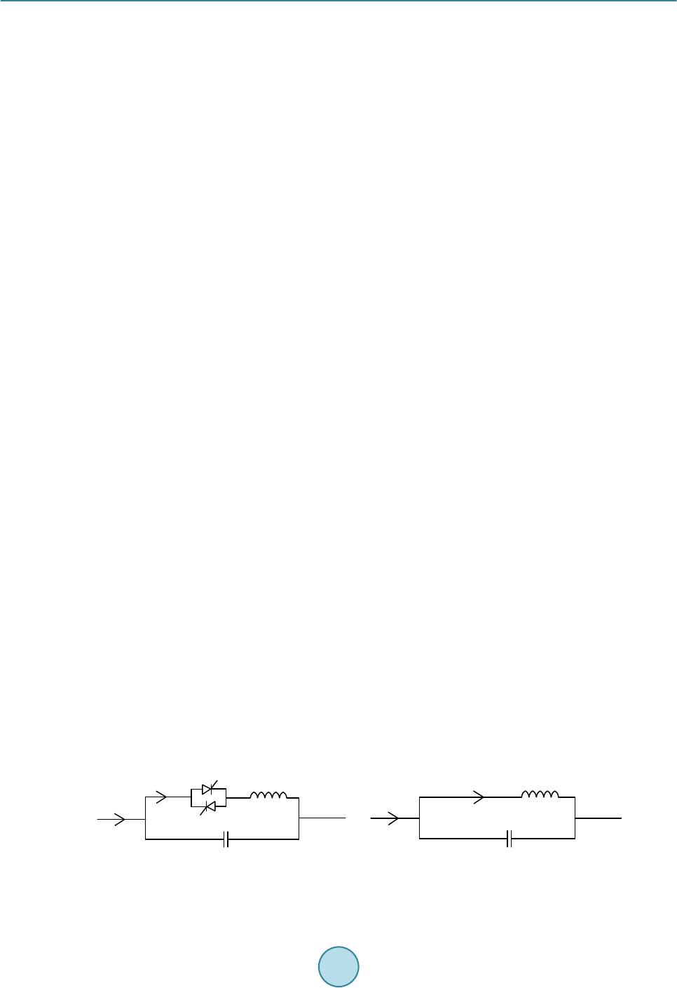 R. Zheng et al. TCSC, as a controllable device, enables application of low-level control strategy to regulate TCSC characte- ristic to d amp SSR problems. The 220 kV Kayent a substation [1] uses TCSC equipped with closed -loop current controller to help solve S SR p roblems. In the Stode project [2], SVR (Synchronous V oltag e Reversal) scheme is applied to maintain TCSC apparent reactance hence SSR problem is solved. It is also sh own that TCSC behaved inductive in most sub-synchronous frequency ranges thus SSR cannot occur. However, as TCSC characteristic is related to its firin g scheme, it cannot be distingu ished whether it is TCS C ’s inherent characteristic or extra con- troller that mitigates SSR. Some efforts have been done to investigate TCSC characteristics. Paper [6] researched on TCS C ’s damping against SSR. By using a complex torque coefficient approach, system electrical damping characteristics within sub-synchronous frequency ranges based on different combinations of TCSC and FSC are obtained. It was indi- cated that TCSC cannot bring in additional damping but it mo ved damping at some frequencies to other fre- quencies. Therefore, in so me cases, TCSC could offer better damping than FSC but in some cases it becomes a wor s e option. This idea was proposed but not enough exp lanation is given. This paper further analyzed this idea in [6] and aims to figu r e out the interactio n between the dynamic beha- viors of TCSC and SSR phenomena. A method to predict TCSC’s damping SSR performance is given by testing whether an equivalent circuit is performing inductive or capacitive at concerned frequency. The occurrence of inductive or capacitive behavior is der iv ed during the intera ction of TCSC dynamic and SSR, and is used to ex- plain why TCSC can worsen or improve SSR damping performance. 2. Principle of TCSC Operation 2.1. Triggering of TCSC TCSC consists of a TCR (Thyristor-controlled Reactor) in parallel with a fixed capacitor. By changing the in- stants that thyristors are fire d , the current flowing through TCR will vary thus the apparent reactance of TCR and TCSC device could be controlled. The typical single-line diagram of TCSC is shown in Figure 1(a). Also, since the TCR reactance is fix e d in steady state, the TCR is approximated to an equivalent inductor as shown in Figure 1(b). The firing instants are defined using a variable, firing angle . This can be transformed into electrical degree fro m fundamental cycle time. By definition, the start point of a firi ng angle is determined by the voltage zero-crossi ng points. However, in practical TCSC projects, as capacitor voltage is less stable than line current, therefore line current is preferable as a reliable input to determine the firing instants. Since TCSC behaves capa- citive in normal operation, the line current leads 90˚ ahead of capacitor voltage . Thus, a newl y formed fir i n g angle is de fi ned as (1) whe r e denotes the new firin g angle starts from current zero-crossing points. Only capac itive conditions are considered throughout this paper. When a TCSC device is fired under steady state conditions, the typical wav e forms of its inductor current , capacitor voltage and line current are shown in Figur e 2. The synchronization bet ween current and thyristor triggering pulses is shown in Figure 2. A practical ap- proach is to detect the zero-crossing points of current . Once a zero-point is detected, this instant is recorded as a reference, e.g. . The desired firin g an gle is transformed into time dela y and then a pplied onto the in- stant . A fte r certain time delay, a pulse is generated and wi l l be sent to thyristor to trigger the current conduc- tion. The trigge ring pulses are in sign with capacitor voltage at that instant. In Figure 2, pulse “a” is generated (a) (b ) Figure 1. Schematic diagrams of TCSC and its equivalent circuit. (a) Schematic diagram of TCSC ; (b) Equivalent circuit of TCSC . 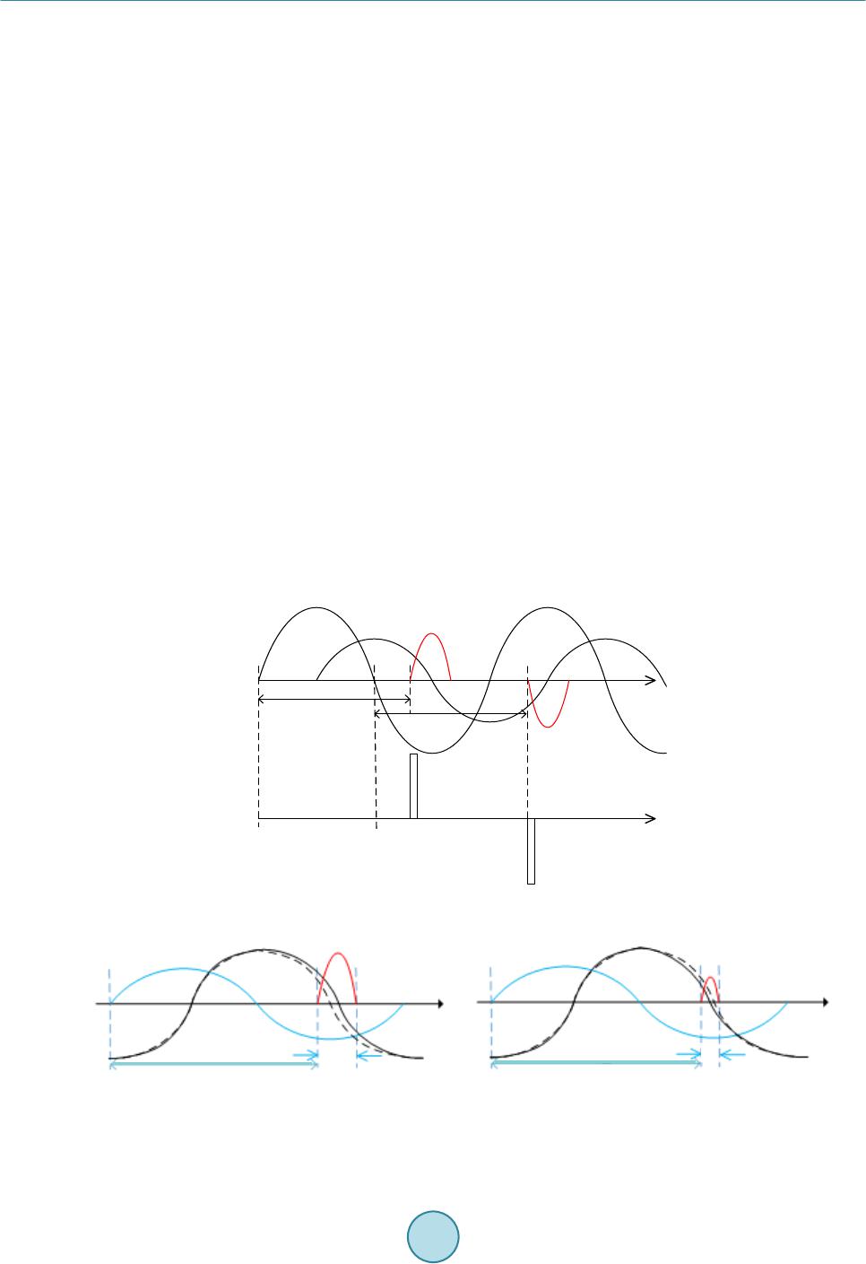 R. Zheng et al. when capacitor voltage is positive, thus it is used to trigger thyristor “a”. In this waythyristors are fired with ac- cordance to line current and selected firing angles. This procedure is repeated to maintain TCSC triggering syn- chronization. 2.2. TCSC Dynamics Considering Impacts of SSR TCSC perfor mance depends on thyristor firing scheme, the interference of sub-synchronous components in ca- pacitor voltage can cause TCSC behavior varied if the firi ng scheme is not regulated with accordance to sub- synchronous components. Figure 3 shows a simple example of the interruption of sub-synchronous voltages when TCSC is fir e d with constant firing angle. In reality, induced sub-synchronous components are quite small (only around 1% in magnitude co mpared wit h fundamental component), therefore, most models in previous studies assume that TCSC on/off switching is not affected. However, this initial small difference can be amplified if no external controllers are installed, and the synchronization of TCSC triggering is lost. In Figure 3, with the penetration of sub-synchronous capacitor voltage component, the frequency of newl y -fo r m ed voltage is slightly changed, thus the half-cycle time between two zero-crossi ng points is different. If the firing logic takes constant delay (firing angle) fro m the last current zero-crossi ng point, the thyristor conducting time is varied. The first half-cycle of the newly-fo rme d capacitor voltage (solid line), as shown in Figure 3(a) , is in- creased due to penetration of sub-synchronous components. This results in longe r thyristo r conducting interval, hence the inductor current is increased compared with that in Figure 2. On the contrary, in Figure 3(b), the fir st cyc le of capacitor volta ge is reduced, thus the inductor current . Note that the sub-synchronous voltage that induced in the circuit is quite small in magnitude compared with fundamental component, i.e. around only 1%. Thus the effective value of capacitor voltage is almost constant. But the inductor current is more sensitive to these changes. Considering the half cycle in Figure 3, the apparent reactance of TCR is decreased due to the i ncreasin g and decr easing . In the second half cycle, the thyristor conducting time is shorten hence corresponding is decreasing. This results in larger . As TCSC is actually a parallel circuit of TCR and fixed capacitor, if varies, the TCSC apparent reactance is changed as well. This α i IVc α i ... ... a b t0t0 + π t0 + 2π I L Figure 2. Typical wav ef orms of inductor current , capacitor voltage and line current . (a) (b) Figure 3. Waveforms of inductor current , capacitor voltage and li n e current with sub-syn - chronous voltage components: (a) First half cycle voltage increased; (b) fi r s t half c ycle decreased.  R. Zheng et al. phenomena repeats until the sub-synchronous components are full y damped, thus is observed to be os- cillating. 2.3. The Equivale n t Circuit of TCSC As the TCSC is operated steadily, , and are all constant. Considering TCSC performance within each half cycle, can be derived using the effec t iv e value of and . As contains only fund a- mental component and its odd order harmonics, Fourier Transform can be used to obtain magnitudes of each component, thus can be written as: (2) whe r e denotes the magnitude of kth order harmonic and k is odd integer. Then the effective value of , denoted by , is given by: (3) Thus the equivalent inductance of TCR, d enoted by is given as: 2 ,fund ,sub,fund EQ 0 ,eff,eff 2 cc c LL VV V LII ω + = ≈ × (4) whereas is the sub-synchronous voltage that is around only 1% of , thus can be ignored. 3. Characteristic of the Equivalent Circuit As the approximation takes fixed inductor and capacitor as its components, the non-linear characteristic caused by TCSC switching can be ignored. Therefore, the frequency response of the paralleled circuit is developed as follow: ( ) EQ ,EQ EQ 2 ,EQ EQ EQ 1 11 CL CL jL X XjL jC ZXX LC jL jC ωω ω ωω ωω ∗ ∗ = == +− + (5) Assign , thus the boundary can be derived as (6) Equation (6) indicated that it is possible to derive the ind uctive behavior range of the equivalent circui t. Ac- tually, as for a TCSC device, the capacitance is fixed. The TCR apparent reactance varies with different operat- ing points, whic h makes the whole TCSC device to perform diffe r e nt l y at concerned sub-synchronous fre q uen- cies. An example is considered here. The compensator is selected to provide 57% compensation level in FBM sys- tem. As TCSC can be tuned to o ffer around 2 ~ 3 times of the base capacitance, thus the fix capacitor is selected equal to 20% of transmission line reactance, which is 34.01 μF. In this case, from the study of [7], the system suffers torsional mode 1 which is at 15.7 Hz. In order to check the SSR response of the system with different sub-synchronous behaviours, three cases are built to make a critical scenario so that the impacts of inductive or capacitive performance can be studied. The parameters of the three cases are sho wn in Table 1. The frequency responses for these three cases are plotted using (5) in Figure 4. Figure 4 illustrates that the resonant point that divides induc tive region and capacitive region is moved when the para meter of inductor changes. As is derived fro m instantaneous capacitor voltage and TCR current in TCSC device, when begins to oscillate, starts to oscillate as well. When , rises from −88 ohm to −94 ohm capacitive, the frequency behavior at 16 Hz is move d fr o m inductive to capacitive region, denoted by red and black curves in Figure 4. In this way, the circuit cannot remove SSR. On the other hand, if 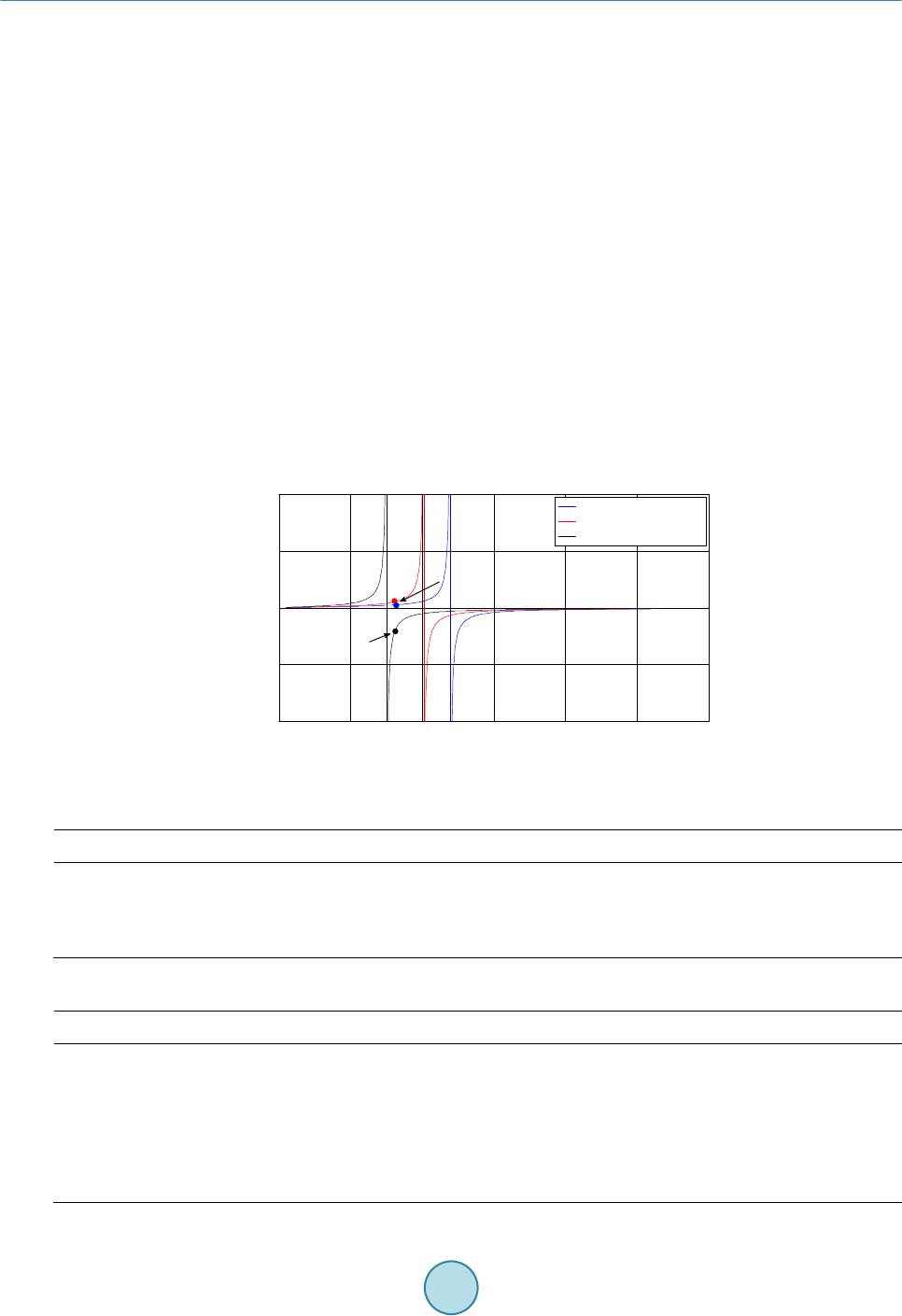 R. Zheng et al. decreases, i.e. fro m −88 ohm to −83 ohm capacitive, the behavior at 16 Hz is still inductive and cor- responding sub-synchronous component can be damped. As the equivalent circuit is derived fro m impedance response of TCSC device, the theory applies for TCSC as well. 4. Simulations and Results 4.1. Paramet e rs The ex ample case considers FBM system wit h a compensa tion level of 57%. The compensator is provided by TCSC or its equivalent circuit only. Table 2 gives the parameters of TCSC and the equivalent circuit parame- ters. 4.2. Simulation Results and Ana lysis Figure 5 gives the LPA-LP B torque in the FBM s yst em operated under 57% compensation level. It is shown that the equivalent c ircuit of TCSC s hows good damping performance against SSR phenomena. In Figure 5, the torque oscillates at around 0.5 p.u. when fa ul t is applied at 4 sec and converges wit h time past. This indicates that the equivalent circuit can damp the 16 Hz component due to its inductive behavior at that frequency whic h is expected using the result s h own in Figure 4. Install TCSC device and remove the equivalent circuit, tuning the firing angle to maintain the same compen- sation level, the simulation result is shown in Figure 6. Figure 4. Frequency response of three cases. Table 1. Thre e combinations of parameter. The equivalent circuit TCS C Case 1 Case 2 Case 3 Table 2. TC S C and its equivalent circuit parameters. TCSC Th e Equivalent ci r cu it of TC S C Inductance 23 mH 1821 mH Capacitance 34.01 μF 34.01 μF Firing angle 163.5˚ N/A TCSC ap pa ren t rea ct an c e at 60 Hz −88 Ω −88 Ω Compensation level 57% 57% 010 20 30 40 5060 -1 -0.5 0 0.5 1x 10⁴ Frequency (Hz) React ance (ohm) Case 1, Leq=3300 mH Case 2, Leq=1821 mH Case 3, Leq=1300 mH Inductive Capacitive 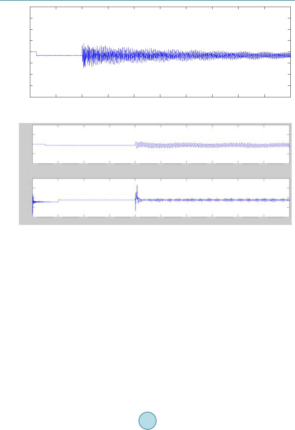 R. Zheng et al. Figure 5. LP A-LPB torque withequivalent circuit of TCSC . TCSC apparent r eactan ce ( - 1 * ohm) Figure 6. LPA-LPB torque (upper) and TCS C apparent reactance with closed-loop triggering logic (lower). In Figure 6, the torque gets oscillated at fir st around 0.5 p.u. and starts to damp after fault cleara nce. The TCSC reactance plot sho ws that the impedance controller is maintaining at reference level while a s mall oscilla- tion due to PI controller can be observed. The above results show that TCSC can damp SSR problems when its corresponding sub-synchronous beha- vior is inductive and its charac te ristic is maintained. This is theoretically derived using the frequency respo nse of the equivalent cir c uit. Therefore, it is necessary to validate whether a capacitive behavior would amplify SSR problems. 5. Validation and Results When TCSC reactance starts to oscillate using open-loop scheme, the possible reactance oscillation range can be various. As shown in Figure 4, under some conditions, the behavior at 16 Hz may turn into capacitive. Consider case 3 in whic h the equivalent reactance is selected to be −83 ohm, as sho wn in Table 3. As shown in Figure 4, the circuit behaves capacitive at 16 Hz, hence the circuit is expected to amplify SSR problem. The simulation result is s hown in Figure 7. Figure 7 shows that the LP A -LP B torque gets oscillated as faul t is applied. This oscillatio n increases very fast to 15 p.u. in 2 seconds. This indicates that capacitive behavior cannot solve SSR problems but a mplify the sub-synchronous components to result in further oscillatio n. Equip T CSC into system to replace the equivalent L-C cir c uit, and change firing angle to make TCSC fund a- mental reactance equal to −83 ohm. From the previous analysis, the sub-synchronous behavior at 16 Hz is capa- citive in this case. Simulation result is shown in Figure 8. 0246810 12 14 16 18 20 -4 -3 -2 -1 0 1 2 3 4 time (sec) LPA-LPB torque (p.u.)  R. Zheng et al. Table 3. Parameters of the equivalent circuit of TCSC. Inductance 3000 mH Capacitance 34.01 μF TCSC apparen t rea ctan ce at 60 H z 83 Ω Compen sation level 51% Figure 7. LP A-LP B torque withequivalent circuit of TCS C. Figure 8. LP A-LPB torque (upper) and apparent reactance response of TCSC with closed-loop controller (lower). Figure 8 shows that even TCS C d evice can not solve SSR problems under this operating condition. However, compared with the equivalent circuit in Figure 7, the torque oscillation amplitude remains much lower, whi c h is 0.5 p.u. at 4 sec to 2 p.u. at 20 sec. This difference between TCSC and equivalent circu its performance indicate that similar sub-synchronous behaviors, either inductive or capacitive. However, the acti ve regulatin g characte- ristic of TCSC has b etter impacts than the equivalent circuit in damping SSR problems. The results validate the relationships between inductive or capacitve sub-synchronous behaviors and corres- ponding SSR damping performances. It is indicated that SSR can be solved if a circuit provides inductive beha- vior at concerned frequency, while capacitive behavior will amplify SSR problems. 6. Conclusion The frequency response of the equivale nt circuit is obtained and it illustrates that the circuit can damp SSR at 012345678910 -40 -30 -20 -10 0 10 20 30 40 time (sec) LPA-LPB torque (p.u.) 0246810 1214 161820 -4 -2 0 2 4 time (sec) LPA-LPB torque (p.u.) 02468 101214161820 0 50 100 time (sec) TCSC a pp a rent rea tance (*-1 oh m)  R. Zheng et al. concerned sub-synchronous frequency if corresponding behavior is inductive. This sub-synchronous behavior wil l be mov ed if the equivalent inductance is varied, which is related to dynami c of TCR. TCSC impedance sta- bility is related to its SSR damping performance, as long as its sub-synchronous behaviors at concerned fre- quency are inductive. However, it is also noted that the dynamic of TCSC may sometimes turn its behavior into capacitive, which will lead to a SSR failure. Therefore, a proper controller to limit the output of TCSC apparent reactance or other variables is helpful to improve SSR performance. The capacitive sub-synchronous behavior has been validated to be amplifying SSR problems, but the comparison between TCSC and its equivalent circ uit shows that even in the same capacitive conditions, TCSC’s inherent regulating has better impacts on decreasing the slope of oscillations. Acknowledgements The author gratefully ackno wledges Jun Lian g for his advice and guidance throughout thi s research, and Ge n Li for preparing mo st of the figures and plots. Without their help, it is impossible to complete this paper. References [1] Christi, N., Hedin, R., Johnson, R., Krause, P. and Montoya, A. (1991) Powe r System Studies and Modelling for the Kayen ta 230 kV Substation Advanced Series Compensation. International Conference on AC and DC Power Trans- mission, 17-20 September 1991, 33-37. [2] Holmberg, D., Danielsson, M., Halvarsson, P., et al. (1996) The Stodethyristor Controlled Series Capacitor. CIGRE, Paris, 14-105. [3] Lian g , J., Guo , J.B. and Zhou, X.X. (1998) Theory Ana ly s is and Engineering Study of Yimin -Fengtun 500 kV TCSC Transmission System. International Conference on Power System Technology, 1, 377-381. [4] ENSG. Our Electricity Transmission Netwo r k : A Vision for 2020. https://www.gov.uk/government/uploads/system/uploads/attachment_data/file/48274/4263-ensgFull.pdf [5] Subsynchronous Resonance Working Group (1980) Proposed Terms and Definitions for Subsynchronous Oscillations. IEEE Transactions on Power Apparatus and Systems, PAS-99. [6] Wu, X. and Jiang, P. (2010) Borrow Damping Phenomena of TCS C to Sub-Synchronous Resonance. Power System Protection and Control, 38. [7] IEEE Subsynchronous Resonance Task Force of the Dynamic System Performance Working Group Power System En- gineering Committee (1977) F ir st Benchmark Model For Computer Simulation of Subsynchronous Resonance. IEEE Transactions on Power Apparatus and Systems, PAS-96.
|