 Journal of Power and Energy Engineering, 2015, 3, 170-177 Published Online April 2015 in SciRes. http://www.scirp.org/journal/jpee http://dx.doi.org/10.4236/jpee.2015.34024 How to cite this paper: Su, H.-Y., Chen, Y.-C. and Lin, J.-C. (2015) Online Maximum Loadability Monitoring Scheme for Smart Grid. Journal of Power and Energy Engineering, 3, 170-177. http://dx.doi.org/10.4236/jpee.2015.34024 Online Maximum Loadability Monitoring Scheme for Smart Grid Heng-Yi Su1, Yi-Chung Chen2, Jia-Chuan Lin3 1Department of Electrical Engineering, Feng Chia University (FCU), Taichung, Taiwan 2Department of Information Engineering and Computer Science, Feng Chia University (FCU), Taichung, Taiwan 3Department of Automatic Control Engineering, Feng Chia University (FCU), Taichung, Taiwan Email: hengyisu@fcu.edu.tw Received January 2015 Abstract This paper presents an algorithm based on Thevenin equivalent network for voltage stability evaluation. The proposed algorithm provides a technique for online predicting the largest possi- ble margin to voltage collapse of an electrical power system. An online maximum loadability de- termination algorithm is developed by transforming the impedance margin, obtained from the Thevenin equivalent network, into the loading margin at each of the load buses in a power system. Furthermore, the proposed algorithm also takes system load trends into account for practical ap- plications. The effectiveness of the proposed algorithm is tested on the IEEE 14 and 57 bus test systems. Simulation results have shown that the proposed algorithm is useful and practical for on- line voltage instability monitoring. Keywords Maximum Lodability, Online Monitoring, Smart Grid, Thevenin Equivalent, Voltage Stability 1. Introduction Many power system blackouts throughout the world have been mainly caused by the phenomenon of voltage in- stability. These voltage collapse problems have threatened power system reliability and security. In recent years, voltage stability is a serious concern in power system operation. Several methods for voltage stability analysis techniques are discussed in [1] [2]. When power systems are operated closer to their maximum loading condi- tions, there is a necessity to release tension of the transmission network. Nevertheless, maximum loading of a power system is not a fixed quantity. Various factors which can vary with time, such as: transmission network topology, generation status, load patterns, the availability of reactive power reserves, and their locations will all impact such a quantity [3] [4]. As a result, it is critical that system operators use the information of the current operating point to estimate the distance of power system state to the voltage collapse point. For power system planning and operation, the conventional P-V curves are widely used to determine the loading margin within voltage stability limit. The P-V curve is generated by executing a large number of load- flow analysis. To overcome the uncertainty of the load-flow convergence, the continuation power flow (CPFLOW)  H.-Y. Su et al. based methods were proposed in [5] [6]. Owing to the CPFLOW based methods are usually time-consuming for a large-scale power system; they may not be appropriate for online application, so alternative approaches are needed. The methods proposed in [7]-[10] are called the local methods based on tracking the Thevenin equivalent pa- rameters by local voltage and current phasor measurements. The central principle of the local method is that: when voltage collapse occurs at a load bus, both the Thevenin equivalent impedance and the load impedance have the same value. Thus, tracking the impedance margin, the difference between the Thevenin equivalent im- pedance and the load impedance, is essential for this kind of method. However, using this approach to determine voltage stability, only the impedance-based margin can be obtained. Instead of the margin in terms of the im- pedance, the loading margin of a power system is more helpful for system operators and planners. In order to identify voltage instability and to predict the maximum loadability of a power system, an algo- rithm which is more efficient and practical is proposed in this paper. The remainder of this paper is organized as follows: Section 2 gives a brief introduction for the local method based on Thevenin equivalent network. Section 3 describes the organization of the proposed algorithm for online power system voltage stability analysis. Simu- lation results on standard IEEE benchmark systems are illustrated in section 4. Conclusion is provided in Sec- tion 5. 2. Basic Concept of the Thevenin Equivalent Network Method In this section, we review the basic concept of the local method proposed in [7] for voltage security evaluation. Such an approach is based on an estimated Thevenin equivalent network behind a load bus. Let us begin with a load at the ith bus connected to a complex power system, which can be simplified into a two-terminal Thevenin equivalent network as shown in Figure 1. The rest of the power system is treated as the Thevenin equivalent network consisting of the Thevenin equivalent voltage behind the Thevenin equivalent im- pedance. Also, let thithi i thithi i LiLi i EE ZZ ZZ β α θ = ∠ = ∠ = ∠ (1) Be the symbol of the Thevenin equivalent voltage, the Thevenin equivalent impedance, and the load im- ped- ance in phasor representation at bus, respectively. Applying Kirchoff’s voltage law to the electrical circuit in Figure 1, then is given by (2) where and correspond to the voltage and current phasors of the load at bus. For a given load power factor, the load power at bus i can be expressed as ( ) 2 22 cos 2 cos Li thii i thiLi thiiiLi ZE PZ ZZZ θ αθ =+ −+ (3) Suppose that the load at bus i is to be increased up to a point at which the maximum power transfer occurs. At this point, the electrical circuit in Figure 1 satisfies the following conditions: ( ) thi ii thi Li EV V ZZ ∗ −= = (4) In other words, as voltage collapse takes place at bus i, is equivalent to . That is, the critical point at voltage collapse is also the point in which the maximum available power can be delivered to the load. Thus, and play important roles in voltage instability monitoring with conditions below: St a b le Unstable Li thi Li thi ZZ ZZ >⇒ ≤⇒ (5) To illustrate the previous paragraph, Figure 2 diagrams the relationship between and in the 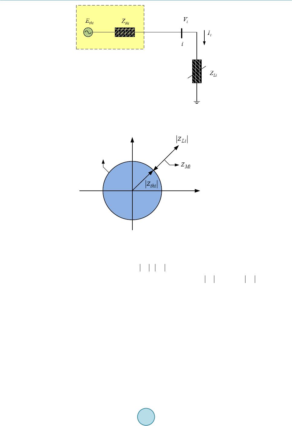 H.-Y. Su et al. Figure 1. Thevenin equivalent network at bus i. R jX Voltage Stability Boundary Figure 2. Representation of impedance margin in R-X plane. impedance plane (R-X plane), in which the impedance margin at bus i, denoted by , is defined to be. (6) In the context of the preceding discussion, at the voltage-collapse point, equals to , which means ZMi closes to zero when voltage collapses at bus i. Based on the concepts described above, several impedance-based indices have been proposed in the works of [7]-[10]. Even though these indices can be adopted to identify whether or not the current operating condition of a power system is stable, information about the maximum available power that a system can be delivered to the load cannot be obtained by those impedance-based methods. In fact, the specific value like maximum loadability or loading margin of a power system is more useful to system operators and planners. 3. The Proposed Algorithm This section presents an algorithm that can estimate the loading margin corresponding to the current operating point. The main idea of the proposed algorithm is to transform the impedance margin, obtained from the The- venin equivalent network, into the loading margin at each of the load buses. In addition, load changes at the in- dividual buses are considered as well. Suppose that the voltage phasor Vi and current phasor Ii are available at load bus , the complex load variation at bus i can be measured by  H.-Y. Su et al. ( )( )() ( )( )()() 1 11 i ii ii ii SkSk Sk VkIkVkI k ∗∗ ∆ =−− =⋅− −⋅− (7) where the letter k represents the kth sampling point. Indeed, the complex load variation can have significantly effects on the load impedance and the Thevenin equivalent parameters, which means the impedance margin is involved as well. Solving for requires and . To find , consider the loads at bus vary li- nearly. The changes of complex load powers can be transformed into the changes of load impedances. As a consequence, at the sampling point k can be computed by (8) To compute , consider the Thevenin equivalent network in Figure 1. Since the local voltage and current phasors are available, the Thevenin equivalent parameters can be computed by the methods proposed in [7]-[10], i.e. can be obtained. With and , ZMi can be computed by Equation (6). We are now finished with the impedance mar- gin involving the load change, so the next step is to transform the calculated impedance margin into the corres- ponding loading margin. In the following, we develop an algorithm that can formulate the transformation between the impedance mar- gin and the load margin at each of the load buses. The technique that we use to derive such an algorithm is called linear fractional transformation with matrix method [11]. To illustrate the algorithm, start by increasing the load at bus i in Figure 1. The trajectory of and at bus i is plotted in Figure 3. It can be seen that is equal to when the maximum deliverable power is reached. From Figure 3, the load margin at bus i, denoted by PMi, is defined to be (9) where and are the current operating value of real power and the maximum deliverable power at bus i, respectively. Suppose that there exists a transformation T such that . In this case, T is called the transforma- tion between ZMi and PMi, and such a T can be expressed as the form of linear fractional transformation ( ) Mi Mi MiMi aZ b P TZcZ d ×+ == ×+ (10) where a, b, c, and d are all complex numbers. Furthermore, T can be presented by a matrix form as (11) If a, b, c, and d in Equation (11) are known, ZMi can be transformed into PMi accordingly. Figure 3. Trajectory of |ZLi| and |Zthi| as load increases .  H.-Y. Su et al. Figure 4 illustrates the overall transformation diagram between ZMi and PMi. Since T cannot be obtained di- rectly, T1 and T2 are required to gain T. The relationship between T1, T2, and T is (12) As long as T1 and T2 are found, T can be solved by Equation (12). In solving T1 and T2, two helpful parame- ters must be defined in advance. First, define the voltage stability index at bus i to be (13) Then, define r as the ratio of ZMi and (14) Solving for r by the definitions of ZMi and and after some manipulations gives ( ) 21 cos Li thiii Mi ZZ rZ αθ +− = (15) Clearly, whenever ZLi and Zthi are known, r is also achieved. Now T1, T2, and T in Figure 4 can be derived by means of linear fractional transformation with matrix method. According to Figure 4, , so T1 can be expressed as ( ) 1 021 cos 10 Li thiii ZZ T αθ +− = (16) Similarly, T2 can be found by (17) Since , this equation gives () 0 0 021cos i Mi Li thiii PZ TZZ αθ × = +− (18) With this approach to computing T, for , PMi can be found by taking each of ZMi into Equation (18). Notice, due to ZMi with Si considered, which implies that the actual load increase direction is also contained in the computed PMi. Impedance MarginPower Margin Figure 4. Transformation diagram between ZMi and PMi.  H.-Y. Su et al. As stressed earlier, a load increase direction has a lot to do with a load margin estimation. Consequently, for the system load margin, denoted by PSM, can be expressed as the sum of PMi estimated at each of the load buses. (19) 4. Simulation Results The proposed method is applied to two sample power systems: IEEE 14-bus and IEEE 57-bus power systems. The programs are coded in MATLAB and implemented on a PC which has a CPU with Intel® Core™ i5 1.8 GHz and a memory with 8 GB. To demonstrate the robustness of the proposed method, the simulations are conducted in different cases, in- cluding various system and load conditions. Moreover, in this paper the simulation results obtained are all com- pared with those found by the conventional CPFLOW method which results are considered as the exact values. More details are presented and discussed as follows. 4.1. IEEE 14-Bus System The first test system is concerned with the IEEE 14-bus test system which is composed of 20 branches, 5 gene- rators, and 9 loads [12]. Two kinds of load patterns, the single load bus variation and multiple load bus variation, are considered. In addition, bar charts are employed to demonstrate the simulation results. In this study, a lot of test cases on the IEEE 14-bus system have been studied. The selected simulation results are illustrated in Figure 5. The maximum loadability value of the selected cases are plotted on the Y-axis of the figure; the bars in left-slanted lines represent the results obtained by the proposed method and the bars with criss-cross lines denote the exact values. As Figure 5 shows, the proposed method is able to provide the results with acceptable accuracy. 4.2. IEEE 57-Bus System The IEEE 57-bus system is also used as a test model to demonstrate the applicability of the proposed method to bulk power systems. This simulated system consists of 80 branches, 7 generators, and 42 loads [12]. In order to evaluate the performance of the proposed method, we have studied a lot of test cases. These include different load levels and load patterns. The selected simulation results among those cases are shown in Figure 6. From the shown figure, it is clearly seen that the errors of the proposed method are within a relatively small range. Fig ure 5. Performance evaluation of the proposed method under the test cases for the IEEE 14-bus system.  H.-Y. Su et al. Fig ure 6. Performance evaluation of the proposed method under the test cases for the IEEE 57-bus system. 5. Conclusion In this paper, a new approach to monitor and identify voltage instability of a power system is presented. Specif- ically, an on line loading margin estimation algorithm with load changes considered is developed. Moreover, the proposed algorithm is a simple, fast, and stable t e chnique that can be applied in the field of online applications. Due to the advent of the method, the proposed algorithm can achieve an excellent performance for the determi- nation of maximum lodability of the transmission network. In this study, we have run a great deal of simulations on two standard IEEE benchmark systems, and satisfaction is within the results. Acknowledgements This work was supported by the Ministry of Science and Technology of Taiwan, R.O.C., under Contracts MOST 103-2221-E-035-101 and MOST 103-2218-E-035-018. References [1] Schluet er, R.A. (1998) A Voltage Stability Security Assessment Method. IEEE Transactions on Power System, 13, 1423-1438. http://dx.doi.org/10.1109/59.736286 [2] Kundur, P., et al. (2004) Definition and Classification of Power System Stability IEEE/CIGRE Joint Task Force on Stability Terms and Definitions. IEEE Transactions on Power System, 19, 1387-14 01. http://dx.doi.org/10.1109/TPWRS.2004.825981 [3] Van Cutsem, T. and Vournas, C. (1998) Voltage Stability of Electric Power Systems. Kluwer, No rwell, MA. http://dx.doi.org/10.1007/978-0-387-75536 -6 [4] Kundur, P. (1994) Power System Stability and Control. McGraw-Hill, New York. [5] Ajjarapu, V. and Christy, C. (1992 ) The Continuation Power Flow: A Tool for Steady State Voltage Stability Analysis. IEEE Transactions on Power System, 7, 416-423. http://dx.doi.org/10.1109/59.141737 [6] Chiang, H.D., Flueck, A.J., Shah, K.S. and Balu, N. (1995) CPFLOW: A Practical Tool for Tracing Power System Steady-State Stationary Behavior due to Load and Generation Variations. IEEE Transactions on Power System, 10, 623-634. http://dx.doi.org/10.1109/59.387897 [7] Vu, K., Begovic, M.M., Novosel, D. and Saha, M.M. (1999) Use of Local Measurements to Estimate Voltage-Stability Margin . IEEE Transactions on Power System, 14, 1029-10 35 . ht tp:// dx. do i.or g/1 0.11 09 /59 .78 0916 [8] Verbic, G. and Gubina, F. (20 04) A New Concept of Voltage-Collapse Protection Based on Local Phasors. IEEE Transactions on Power Delivery, 19, 576 -581. http://dx.doi.org/10.1109/TPWRD.2004.824763  H.-Y. Su et al. [9] Smon, I., Verbic, G. and Gubina, F. (2006) Local Voltage-Stability Index Using Tllegen’s Theorem. IEEE Transac- tions on Power System, 21, 1267-1275. http://dx.doi.org/10.1109/TPWRS.2006.876702 [10] Corsi, S. and Taranto, G. N . (2008) A Real-Time Voltage Instability Identification Algorithm Based on Local Phasor Measure ments . Transactions on Power System, 23, 1271-1279. http://dx.doi.org/10.1109/TPWRS.2008.922586 [11] Dubrovin, B.A., Fomenko, A.T. and Novikov, S.P. (19 84 ) Modern Geometry—Methods and Applications. Springer- Verlag. http://dx.doi.org/10.1007/978-1-4684-9946-9 [12] Power Systems Test Case Archive, University of Washington College of Engineering. [Online] http://www.ee.washington.edu/re-serach/p stcal/.
|