 Journal of Power and Energy Engineering, 2015, 3, 128-135 Published Online April 2015 in SciRes. http://www.scirp.org/journal/jpee http://dx.doi.org/10.4236/jpee.2015.34019 How to cite this paper: Fu, Y., Huang, L.S. and Zhao, J.J. (2015) Micro -Grid Smooth Switchover Method Based on Controller State Following. Journal of Power and Energy Engineering, 3, 128-135. http://dx.doi.org/10.4236/jpee.2015.34019 Micro-Grid Smooth Switchover Method Based on Controller State Following Yang Fu, Lisha Huang, Jingjing Zhao Shanghai University of Electric Power, Shanghai, China Email: mfudong@126.com, lisa0706@live.cn, jjzhao_sh@163.com Received January 2015 Abstract Micro-grid smooth switchover between different operation modes is important for steady opera- tion and reliable power supply of micro-grid. In order to reduce the transient fluctuation of vol- tage and frequency during switchover, this paper proposed a new switchover method based on controller state following. When transferring to island mode, the control method for inverter of storage device changed from PQ control to V/f control. Before switchover, the output of V/f con- troller is always following the output of PQ controller. So that the sudden change of output is avoided at the moment of switchover. A micro-grid model with photovoltaic and battery is built on DIgSILENT Powe r Factory simulation software, to simulate micro-grid switchover from grid-con- nected mode to island mode. Results show this method can effectively suppress the transient fluc- tuation of voltage and frequency, and reduce the influence of transient process on power grid. This conclusion has important practical significance on micro-grid smooth switchover from grid-con- nected mode to island mode. Keywords Micro-G rid, Smooth Sw itch over, Controller State Following 1. Introduction As fossil fuel supply becomes steadily tighter and electricity demand continues to grow, distributed generation technology based on renewable energy are beginning to attract wide attention. Distributed generation will un- doubtedly be strong complement and effective support to bulk power grids, and be a trend of future power sys- tem development [1] [2]. To give full play to the advantages of distributed power generation technology, one or more distributed power (DG), energy storage device and controllable load form a micro-grid according to cer- tain topological structure. Grid-connected mode is when micro-grid is connected to the main grid and island mode is when micro-grid is isolated from the main grid. Both are normal operation status of micro-grid . Proper control strategy is key to the steady operation of micro-grid [3] [4]. Micro-grid smooth switchover between grid- connected mode and island mode is the emphasis and difficulty of micro-grid control strategy research and is important for steady operation and reliable power supply of micro-grid. At present, many experts and scholars at home and abroad have studied on the smooth switchover control 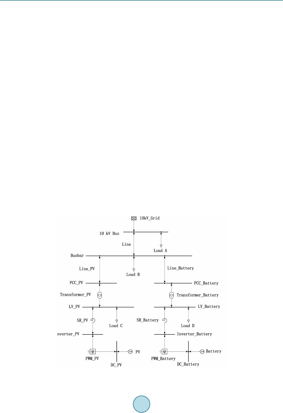 Y. Fu et al. strategy of micr o -grid. In [5] takes the integrated energy storage device composed of super capacitor and battery as the main power supply during the island mode of micro-grid, where proper control of charge and discharge of the integra ted device can realize smooth switchover of micro-grid. In [6] a bi-directional inverter is used to switch the control method of storage device changed from PQ control to V/f control, stabilizing voltage and frequency of micro-grid in island mode and realizing smooth switchover between two operation modes. It is the common smooth switchover strategy. However, this strat egy neglects the non-sync hronization of controller switchover and mode switchover, and will easily cause overshoot current and voltage fluctuation during the switch proce ss. To avoid this situation, a voltage and current weighted control strategy without increasing sys- tem complexity is presented in [7], achieving seamless switchover, but power shortage in the process of switch- over from grid-connected mode to island mode is not considered. In the process of mode switchover especial the switch moment, the non-synchronization of controller switch- over and mode switchover as well as unbalanced power between DGs and loads may lead to large fluctuation of voltage and current, causing ne ga tive impacts on micro-grid stable operation. Moreover, serious consequences like frequency instability and voltage collapse might happen. In order to decrease transi e nt fluctuation of voltage and frequency in the process of switchover, this paper proposed a micro-grid smooth switchover method based on controller state following and built a micro-grid model on DIgSILENT Power Factory simulation software to verify the effectiveness of proposed method. 2. Control Strategy of Micro-Grid 2.1. Micro-Grid Configuration Figure 1 shows the micro-grid configuration of study case. Photovoltaic and battery as distributed generators access to 10 kV grid through inverters and transformers, and supply power to loads in micro-grid. Load C and Load D are linked to low voltage side of 0.4 kV, and are supplied by photovoltaic and battery directly. In grid- connected mode, the control method for inverters of photovoltaic and battery is PQ control and DGs generate rated power. Voltage and frequency of micro-grid is supported by the grid. When micro-grid disconnects from the grid and transfers to island mode, the control method for inverters of battery changes from PQ control to V/f control and that of photovoltaic maintains the same. At the moment, loads in micro-grid are only supplied by DGs and battery provides support of voltage and frequency for micro-grid as main power source. Figure 1. Micro-grid configuration. 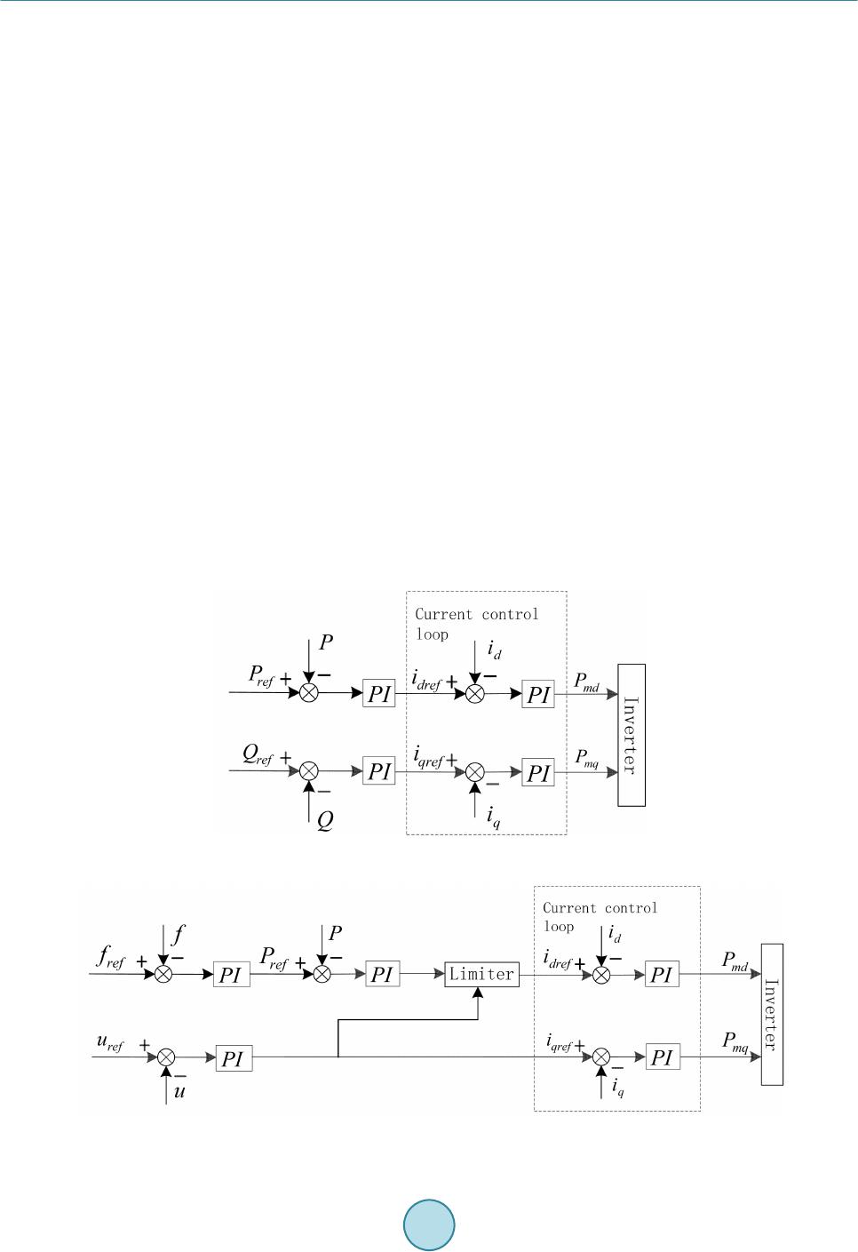 Y. Fu et al. 2.2. Control Modes for DGs PQ control diagram and V/f control diagram are as given in Figure 2 and Figure 3 respectively [8 ]. PQ control takes dual-loop control structure. The internal loop is power control, which ensures power output always track- ing reference power. The inner loop is current PI control, which controls the pulse width modulated signal of inverter. V/f control has a multi-loop feedback control structure including power loop, voltage loop and current loop. The current loop takes d-axis reference current idref and q-axis reference current iqref from power loop and voltage loop respectively. In power loop, the reference active power follows the change of frequency. V/f con- trol can adjust the reference power of DGs according to the voltage and frequency of micro-grid. 3. Method Based on Controller State Following Figure 4 shows the trad ition al switch metho d of the controllers of battery inverter when micro-grid transfers from grid-connected mode into island mode. During grid-connected mode, K1 is closed and K2 is open. The bat- tery takes PQ control mode. When micro-grid disconnects with the grid, K1 opens and K2 closes, so the control mode switches into V/f mode. The generated reference current idref, iqref becomes different .and flows into the current control loop. But this traditional switch method of controllers will lead to great transient fluctuations at switch momentdue to the difference between outputs of two controllers. In grid-connected mode, the PQ con- troller outputs a control signal which flows into the current controlloop, while the output of V/f controller is zero. When transferring into island mode, PQ controller is out of operation and V/f controller takes over it. The input signal of current controlloop instantaneously becomes 0, which leads to the transient fluctuation of voltage and frequency of micro-grid during switchover. To avoid the above situation happens, this paper proposed a new switch method based on controller state fol- lowing, as shown in Figure 5. In grid-connected mode, K1 and K4 are closed while K2 and K3 open. The battery takes PQ control. The difference between out puts of V/f controller and PQ controller is designed as a negative feedback to be put into V/f controller. Through the non -differential control of PI module inside V/f controller, the output of V/f controller always follo ws the output of PQ controller . When the operation mode switches into Figure 2. PQ control diagram. Figure 3 . V/f control diagram. 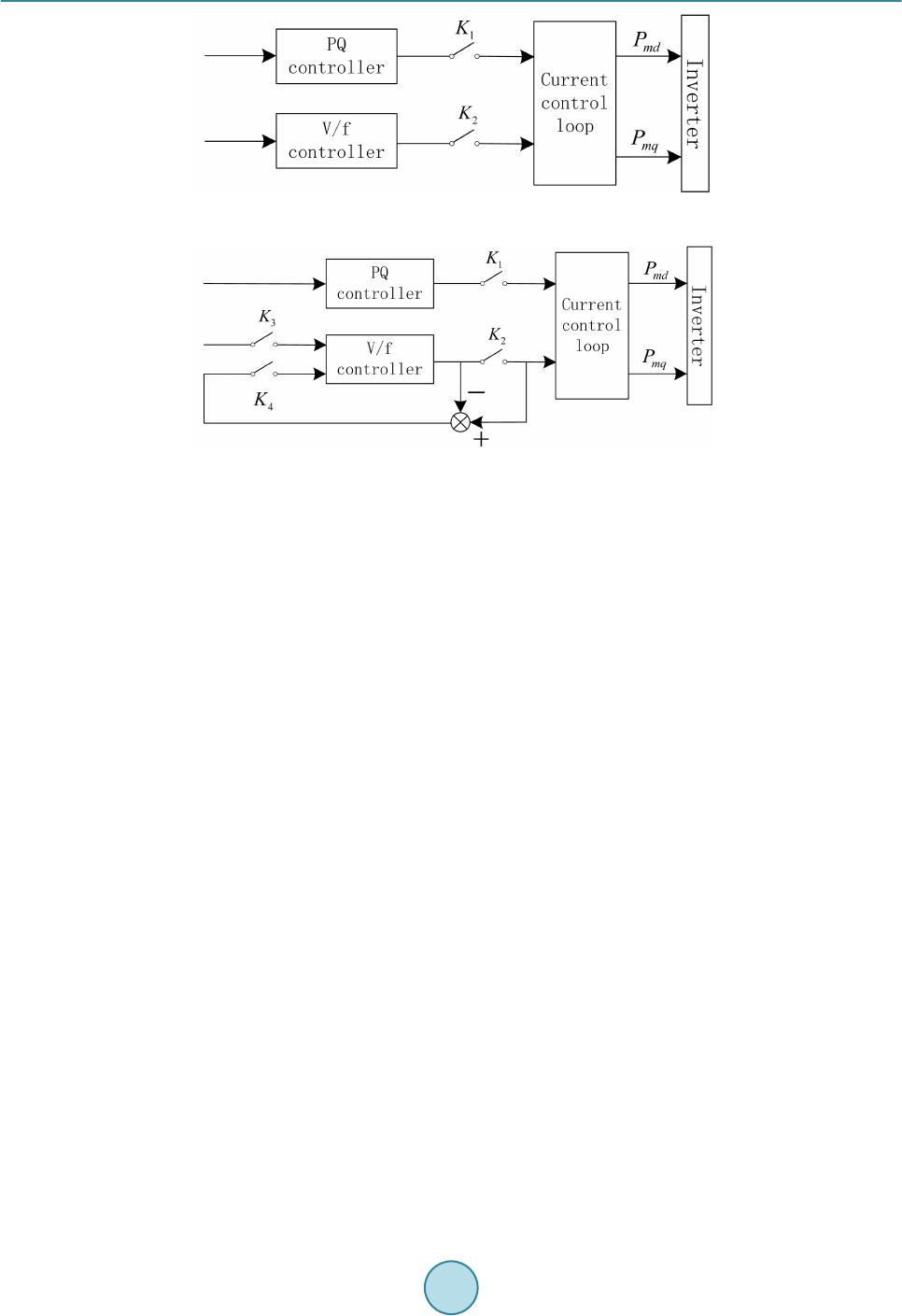 Y. Fu et al. Figure 4. Traditional switch method of controllers. Figure 5. Switch method based on controller state following. island mode, K1 and K4 open and K2 and K3 close. The PQ controller is out of operation and battery takes V/f control. In this way the sudden change of input of current control loop is avoided at switch moment and the smooth switchover of operation mode is realized in micro-grid [9]. 4. Simulation and Analysis The DIgSILENT Power Factory simulation software is used to develop a time-domain simulation model of the study case of Figure 1. DGs’ parameters, loads’ parameters and control parameters of control models are given in Appendix. At initial state when t = 0 - 1 s, micro-grid connects with grid. At t = 1 s, disconnection occurs between micro-grid and grid. Micro-grid comes into island mode. 4.1. Steady State Process Table 1 shows the power flow distribution of micro-grid under grid-connected mode and island mode. It can be seen from Table 1, when micro-grid is in grid-connected mode, Both DGs and the distribution grid offered power to the loads, and the DGs generated rated power. The active power produced by DG sonly can’t meet the demand of loads, so the rest part was supplied by the grid. The grid delivered 0.5 MW active power to the micro-grid, the extra 0.5 Mvar reactive power produced by DG was transmitted to the grid through the con- nection. At this moment, the grid worked to keep the power balance in the micro-grid and maintain the stability of voltage and frequency of micro-gri d . After the operation mode switched into the island mode, micro-grid and the grid were disconnected, and there was no longer any power exchange between the grid and micro-grid. The control mode of battery inverter was changed from PQ control to V/f control to adjust the active and reactive power output as the goal to keep the grid voltage and frequency stabile. Then the active power output of the bat- tery increased from 2 MW to 2.5 MW, reactive power declined from 0.5 Mvar to zero. Meanwhile, micro-grid still kept its balance state of power. The simulation result of power flow in micro-grid is the same with or without the proposed control method of smooth switchover, and the method based on the controller state followi ng has no impact on the steady process of micro-gri d . 4.2. Transient Process The comparison of power output curves of PV and battery before and after the control method improvement are  Y. Fu et al. Table 1. Power flow distribution of micro-grid under grid-connected mode and island mode. Operation Mod e Gr i d -connected mode Island mode Active power/MW Reactive power/Mvar Active power/MW Reactive power/Mvar Source PV 2 0.5 2 0.5 Battery 2 0.5 2.5 0 Gri d 0.5 −0.5 0 0 Power Production 4.5 0.5 4.5 0.5 Load A −1.5 −0.2 −1.5 −0.2 B −1 −0.1 −1 −0.1 C −1 −0.1 −1 −0.1 D −1 −0.1 −1 −0.1 Power Comsumption −4.5 −0.5 −4.5 −0.5 shown in Figure 6 and Figure 7. In order to see the frequency change clearly, the abscissa was shorten scope in the graph to amplify the curve for better observation. It is shown in Figure 6 and Figure 7, before the improvement, the fluctuation of output power of PV and bat- tery is more severe than after, especially at the mode switch moment. After taking the smooth switch control method based on controller state following, the power output of DGs change less, but the steady-state power remains the same in island mode. The improvement sup p r e sse s the transient fluctuation during switching process which may lead to negative effect on the equipment in the micro-gri d. There is a close connection be- tween DG power fluctuations and the fluctuation of micro-grid voltage and frequency, therefore the improve- ment of control method also has a good effect on the improvement of the stability of voltage and frequency. The comparison of micro-grid voltage and frequency curves before and after the control method improvement are shown in Figure 8. From Figure 8 it can be seen that, before the improvement of control method, there appeared transient fluctu- ations of both voltage and frequency in the micro-grid, the maximum voltage range is more than 15%, the fre- quency range is up to 4%. After a short wave, the inverter of the battery takes V/f control to stabilize the voltage and frequency, and adjust the active reactive power output to keep balance of power within the micro-grid. When comes into steady state of island operation, micro-grid voltage and frequency are back to normal. There- fore, although there is a certain power deficiency, the grid still has the ability to keep stable voltage and fre- quency after island. However the fluctuations of voltage and frequency are too bigger to pose a threat to the safety of equipment within the micro-grid, and will affect the stable operation of the micro-grid. After the im- provement, the smooth switch control method based on controller state following reduces the voltage and fre- quency fluctuations. the lowest point of voltage and frequency are picked up. The maximum scope of voltage fluctuation is reduced from 15% to about 2%, while the maximum frequency fluctuations is reduced from 4% to less than 1%. This leads to great improvement on the transient process of micro-grid significantl y. In addition, the duration of frequency fluctuation is reduced after the improvement, and this is helpful to the transient stabil- ity of the micro grid. 5. Conclusions This paper proposed a new control strategy for smooth sw i t c ho ver of micro-grid based on controller state fol- lowing. By analysis of simulation results, conclusions are given as follows: 1) V/f control of battery has ability to keep steady voltage and frequency of micro-grid in island mode, but traditional way of switchover of controllers has negative influence on stability of micro-grid during switchover pro c ess. 2) Micro-grid smooth switchover method based on controller state following can smooth active and reactive output of DGs at switch moment and enhance stability of voltage and frequency of micro-grid. 3) The proposed method can effectively suppress the transient fluctuation of voltage and frequency, and re- duce the transient time to diminish impact on micro-grid and improve its stability and reliability. 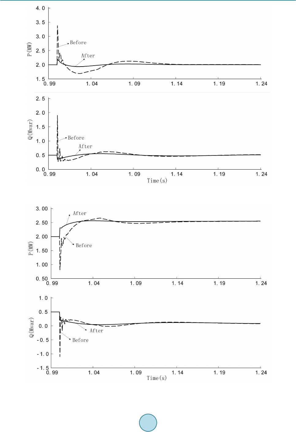 Y. Fu et al. Figure 6. Power output of PV. Figure 7. Power output of battery.  Y. Fu et al. Figure 8. Microgrid voltage and frequency. (a) Micro-grid voltage. (b) Micro-grid frequency. 4) Micro-grid smooth switchover method based on controller state following has no influence on steady state process of micro-grid. Acknowledgements The authors gratefully acknowledge the financial support by Shanghai Green Energy Grid Connected Technol- ogy Engineering Research Center (No. 13DZ2251900) and Shanghai Key Technology R&D Program (No. 13160500800). References [1] Wu , X., Yin, X . G. , Wei, Q., et al. (2013 ) Research on Microgrid and Its Application in China. Energy and Power En- gineer ing, 5, 171-176. http://dx.doi.org/10.4236/epe.2013.54B033 [2] Zhou, X.X., Chen, S.Y. and Lu, Z.X. (2013) Review and Prospect for Power System Development and Related Tech- nologies: A Concept of Three-Generation Power Systems. Proceedings of the CSEE, 33, 1-11. [3] Ari yasi ngh e, M. and Hemapala, K. (2013) Microgrid Test-Beds and Its Control Strategies. Smart Grid and Renewable Energy, 4, 11-17. http://dx.doi.org/10.4236/sgre.2013.41002 [4] Turner, G. , Kelley, P.J. and St orm, L.C. (2014) Design and Active Control of a Microgrid Testbed. IEEE Transactions on Smart Grid, 40, 1432-1436 . [5] Wang, X.H. and Zhang, C.J. (2012) Study of Control Strategy for Seamless Transfer of Grid-Connected Distributed Generation Systems. Transactions of China Electrotechnical Society, 27, 217-222. [6] Yang, Z.G., Wang, C.S. and Che, Y.B. (2009) A Small-Scale Microgrid System with Flexible Modes of Operation. Automation of Electric Power Systems, 33, 89-92. [7] Liu, Z. W., Xia, W.B. and Liu, M.B. (2013) Control Method and Strategy for Smooth Switchover of Micro-Grid Opera- tion Modes Based on Complex Energy Storage. Power System Technology, 27 , 906 -913.  Y. Fu et al. [8] Ren , B.Y., Tong, X.Q., Tian , S., et al. (2010) Research on the Control Strategy of Inverters in the Micro-Gri d. Power and Energy Engineering Conference (APPEEC), Asia -Pacific, Chengdu, 28-31March 20 10 , 1-4. http://dx.doi.org/10.1109/APPEEC.2010.5448341 [9] Zhao, D.M., Zhang, N. and Liu, Y.H. (2013) Synthetical Control Strategy for Smooth Switching between Grid-Connected and Islanded Operation Modes of Microgrid Based on Energy Storage System. Power System Technology, 37, 301- 306. Appendix 1) Reference power of DGs: PV: Pref =2 M W, Qref = 0.5 Mvar Battery: Pref =2 MW, Qref = 0.5 Mvar 2) Constant power of loads: PA=1.5MW,QA=0.2Mvar PB = 1 MW, QB = 0.1 Mvar PC = 1 MW,QC = 0.1 Mvar PD = 1 MW, QD = 0.1 Mvar 3) Parameters of controllers: a) PQ control: PI parameters for Active power loop: KP = 0.5, KI = 0.01 PI parameters for Reactive power loop: KP = 0.5, KI = 0.01 PI parameters for Current control loop: KP = 0.5, KI = 0.02 b) V/f control: PI parameters for Frequency loop: KP = 2, KI = 1 PI parameters for Active power loop: KP = 0.5, KI = 0.01 PI parameters for Voltage loop: KP = 1, KI = 0.005 PI parameters for Current control loop: KP = 0.5, KI = 0.02
|