 Journal of Power and Energy Engineering, 2015, 3, 69-76 Published Online April 2015 in SciRes. http://www.scirp.org/journal/jpee http://dx.doi.org/10.4236/jpee.2015.34011 How to cite this paper: Liang, X.G. and Li, Y.-L. (2015) Predicting Individual Phase Current in Couple Inductor Based Voltage Regulators (VRs). Journal of Power and Energy Engineering, 3, 69-76. http://dx.doi.org/10.4236/jpee.2015.34011 Predicting Individual Phase Current in Couple Inductor Based Voltage Regulators (VRs) Xiaoguo Liang1, Yuan-Liang Li2 1Data Center & Connected System Group (DCSG), Intel Asia Pacific R&D Ltd., Shanghai, China 2Intel Microelectronics Asia LLC, Taiwan Branch Taipei, Taiwan Email: Xiaoguo.liang@intel.com, y.l.li@intel.com Received N ovemb er 2014 Abstract Coupled inductor is one appealing technology to improve transient response and reduce output decoupling significantly in interleaved multi-phase voltage regulators (VRs). One known problem is that there is no mature solution yet to sense the individual phase current accurately in a lossless way for couple inductor based VRs design. This will impact VR some normal function in one phase mode. This paper proposes a new solution to this problem and simulation is conducted to verify effectiveness of the proposal. Keywords Current Sensing, Couple Inductor, Voltage Regulator (VR) 1. Introduction According to the microprocessor’s roadmap, there are several stringent challenges for the future microprocessor voltage regulators (VRs): high output current, low output voltage, high current slew rate and low droop resistance. These challenges require the VRs to have both higher steady state performance and faster transient performance. To improve above issues in today’s multiphase non-coupled VRs, inverse coupled inductor VRs are proposed mainly to improve transient response significantly so that both real estate and cost could be saved on output de- coupling [1] [2]. Some studies also show that inverse coupled inductor could also help improve converter conver- sion efficiency if keeping same transient response as non-coupled multiphase VRs [3] [4]. With all these advan- tages, one known issue for couple inductor based VR design is that there is no good solution yet to accurately sense each individual phase current of VR because of coupling effect between different phases [5]. As shown in Figure 1(a), typically a lossless DCR sensing method is widely adopted in conventional couple inductor based VR design to get total output current information of all the phases with right time constant match. However, as shown in F igure 1(b ), the sensed voltage Vc1 and Vc2 does not exactly conform to individual phase current i1 and i2 [5]. This deviates from the perception that Vc1 and Vc2 should be strictly proportional to i1 and i2. This method can ensure a normal function of VR which depends on total current of multiphase, however, knowing individual 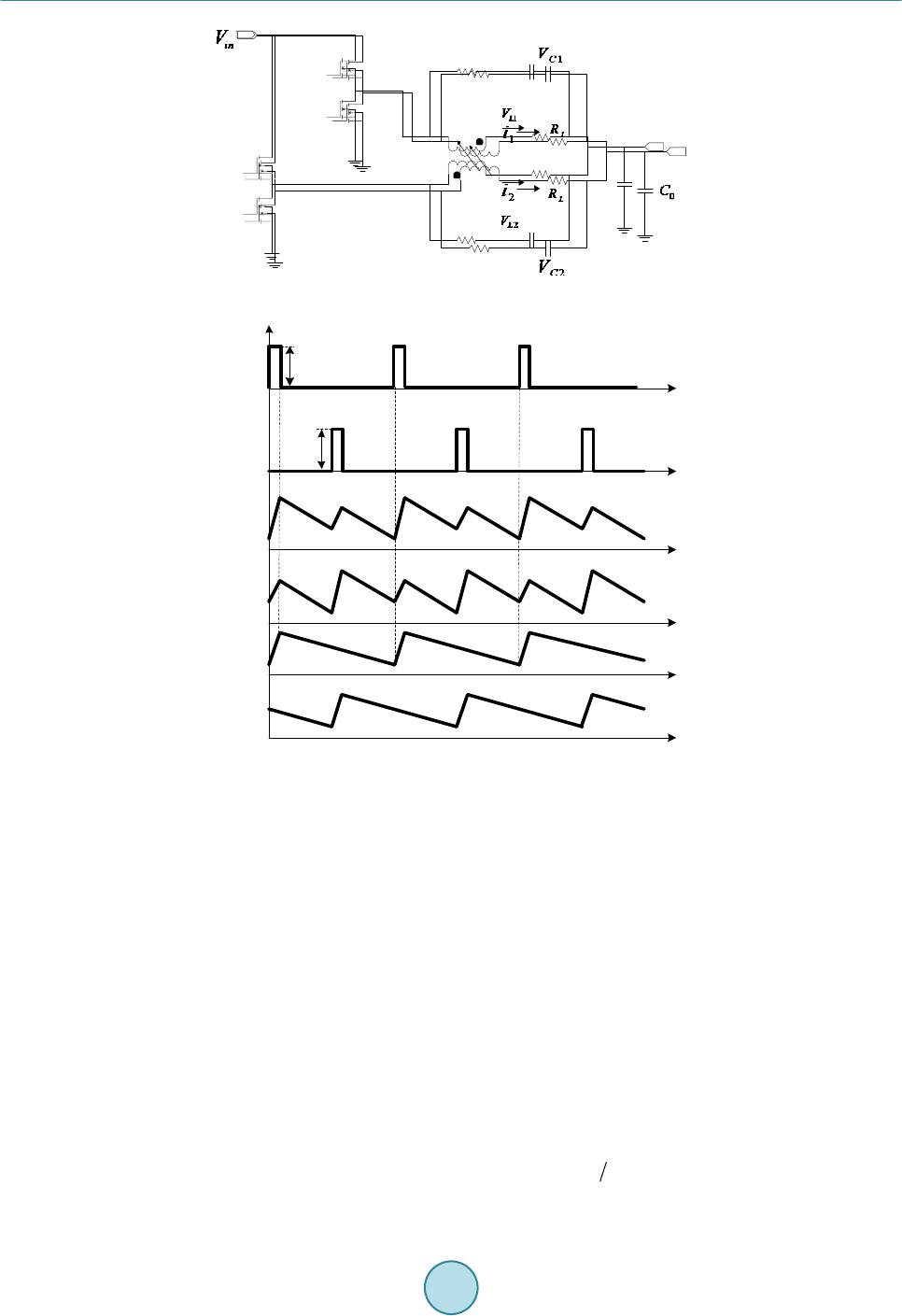 X. G. Liang, Y.-L. Li ph ph 1 1 ph ph 2 2 L L L L M M r r C C r r C C (a) V c1 V c2 i 1 i 2 V ph1 V ph2 T s 2T s DT s V in V in t (b) Figure 1. Traditional 2-phase coupled inductor VR with lossless current sense: (a) circuit; (b) inductor current and sensed voltage at capacitor. phase current is of great importance for phase current balance, power monitor and especial for load line control when VR works under one phase mode (under light load mode). This paper proposes one new method to sense individual phase current of couple inductor based VRs in a loss- less way. Detailed working principle is analyzed and simulation is also conducted to verify the theoretical analy- sis. Even this method is initially proposed for couple inductor application, it’s proved that it’s a universal method which could be applied to both couple inductor and non-couple inductor multiphase buck voltage regulators. 2. Proposed New Current Sensing Method and Its Working Principle 2.1. Proposed Method As shown in F igure 2 and Figure 3, the proposed new current sensing method consists of following ingredients: • One interleaved two-phase coupled inductor VR as shown in Figure 2. it replaces couple inductor in Figure 1 with an equivalent circuit model. Detailed deduction could be found in [5] and is not described here. • For coupled inductor, M is the mutual inductance, L is self inductance, is the leakage inductance and , and k is the coupling coefficient defined as . is DCR of inductor individual winding. 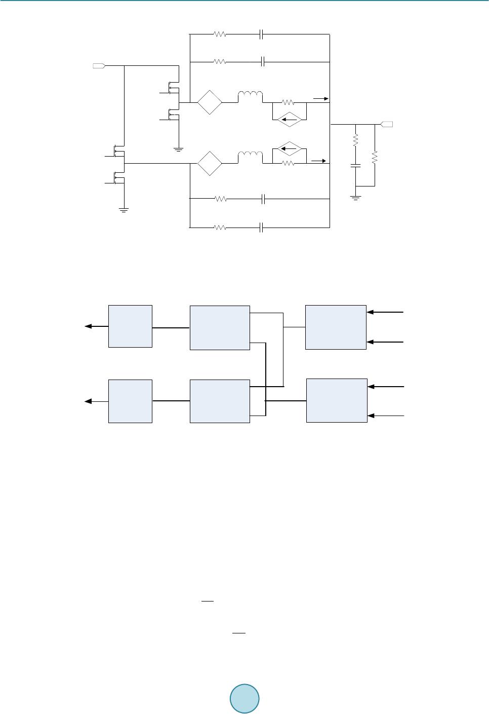 X. G. Liang, Y.-L. Li ph1 ph2 r 1 C 1 r 2 1C V 1L V 2 i 2L V 1 i 2C V + - + - + - + - -+ -+ 2L kV 1L kV k L k L 2 ki 1 ki L R C R 0 R 0 C 0 V in V L R 3C V + - C 2 r 3 C 3 r 4 C 4 + - 4 C V Figure 2. New current sensing for 2-phase coupled inductor VR. + - 4 C V 1 C V 2 C V 3 C V A B A=V c1 +V c2 B=V c3 -V c4 + - Y 1 Y 1 =A+B Y 2 =A-B Y 2 α α I 1 I 2 I 1 =Y 1 * α I 2 =Y 2 * α α α= 1/2R L α= 1/2R L Figure 3. Function diagram to get individual phase current. • Two groups of DCR current sensing networks. Group 1 consists of r1, C1, r2, C2; group 2 consists of r3, C3, r4, C4. There is relationship: , , , . , , and are voltages across C1, C2, C3 and C4 respectively. • Function block including adder, subtracter, proportional amplifier as shown in Figure 3 to get final individual current i1 and i2. The function block could be implemented in either analog or digital way and also could ap- pear in other form/combination so long as it can achieve same mathematic result. 2.2. Working Principle By comparison, proposed method adopts two groups DCR sensing networks instead of one in conventional mul- tiphase buck regulator design. From Figure 2 and Figure 3, following equations could be derived [5]: ( ) 1 12 12 d d Lk LL i vLkvR iki t =−+ + (1) ( ) 2 2 112 d d L LkL i vkvLR kii t =−+ ++ (2)  X. G. Liang, Y.-L. Li where , , and k have same definition as aforementioned. i1 and i2 are individual phase current, and are voltage across L1 and L2 respectively. If transforming Equations (1)-(2) from time-domain to s-do- main, following equations could be obtained: ( )( )( )( )( ) ( ) 11 212L kLL VssL IskVsRIskIs= −++ (3) ( )( )()( )() ( ) 21 212LLkL VskVssLI sRkIsI s =−+ ++ (4) The voltage across C1, C2, C3 and C4 could be represented by Equations (5)-(6): ( )( )( )( ) 12 12 112 2 , 11 LL CC Vs Vs Vs Vs srCsr C = = ++ (5) ( )( )( )( ) 12 34 33 44 , 11 LL CC Vs Vs Vs Vs sr CsrC = = ++ (6) With the fact of: , , , , the relationship of the voltages across the sensing capa- citors can be obtained as: ( )( )( )( ) ( ) 12 12 11 1 11 k CC LL Is IsL VsVs Rs srCR k + += + ++ (7) ( )()( )( ) ( ) 12 34 33 1 11 k CC LL Is IsL VsV sRs sr CRk − −=+ +− (8) If r1 and C1 are selected such that: ( ) ( ) 11 1 1 k LL kL L rC Rk R − = = + (9) Then Equation (7) becomes: ( )()( )( ) ( ) 1 212CC L VsVsRIsIs+= + (10) If r3 and C3 are selected such that: ( ) ( ) 33 1 1 k LL kL L rC Rk R + = = − (11) Then Equation (8) becomes: () ()( )() ( ) 3 412 CC L Vs VsRIsIs −= − (12) In time-domain, (10) and (12) can be expressed as: ( )() ()( ) ( ) ( ) 1 212CC L vtvtRi titAt+ =+= (13) ( )()( )() ( ) ( ) 3 412CC L vtvtRititBt− =−= (14) From (13) and (14), we can get the individual phase current as following: (15) (16) It can be seen that the key to get individual phase current is depended on two steps: first, choose right RC pa- rameters to satisfy Equations (9) and (11); second, derive individual phase current according to Equations (13)- (16). By the way, all above equation derivation is based on couple inductor design with coupling coefficient k. it’s 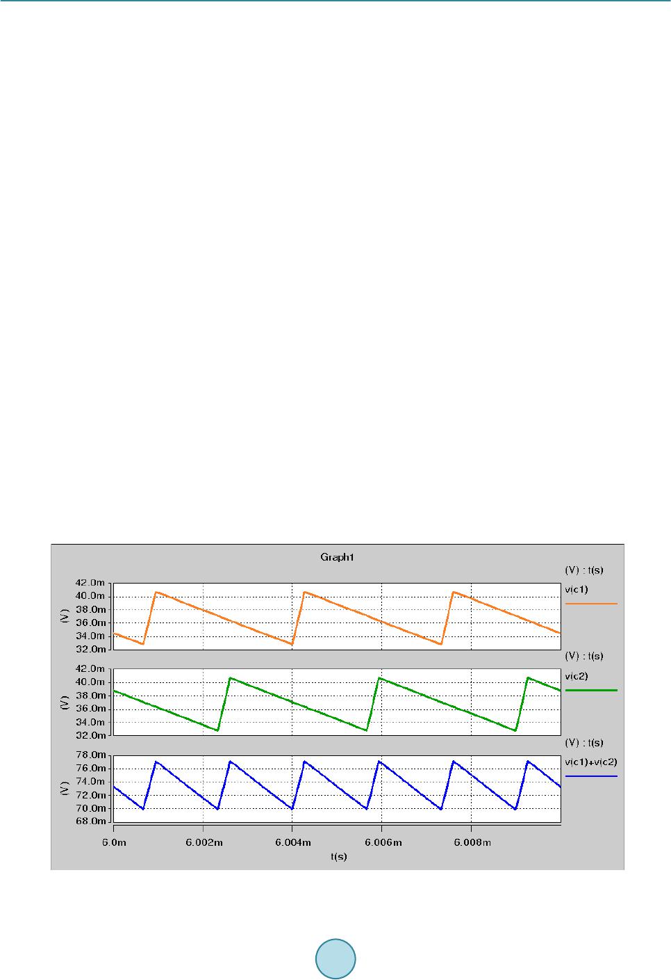 X. G. Liang, Y.-L. Li obvious the condition of k = 0 is corresponded to non-couple inductor design, which indicates this method actual- ly applies to non-couple inductor multiphase VRs as well. 3. Simulation Results Since there is no existed IC solution in industry yet to support the concept verification, simulation is used here as an alternative way to verify the proposed method in this paper. 3.1. For Couple Inductor Design One simulation is conducted for a typical coupled inductor based two-phase interleaved VR design by using Hspice tool. Key parameters are shown as following: Inputvoltage: Vin = 12.6 V; Output voltage: Vo = 1 V; Coupling coefficient: k = 0.6; Self inductance: L = 1 uH; Individual Inductor DCR: RL = 1mohm; Per-phase switching frequency: kHz. Current sense network is designed to satisfy (9) and (11): r1 = r2 = 4 kohm, C1 = C2 = 0.1 uF, r3 = r4 = 4 kohm, C3 = C4 = 0.4 uF. 3.2. Simulation Results Figure 4 shows that voltage across C1 and C2 cannot represent individual phase current i1 and i2, but sum of voltage across C1 and C2 can represent total output current. Figure 5 shows that voltage across C3 and C4 cannot represent individual phase current i1 and i2 either, but (Vc3-Vc4) can represent (i1-i2) according to above analysis even it’s not straightforward yet. As show in Figure 6, i(v1)sim and i(v2)sim are individual phase#1 and phase#2 current directly probed from induc- tors L1 and L2 in simulation circuit which is not feasible to test in practice; i(v1)new and i(v2)new are individual phase#1 and phase#2 current which is obtained by the proposed method. Waveforms for phase#1 and phase#2 current are identical even they are obtained from different way. This verifies the proposed method can accurately predict individual phase current for the couple inductor design. 3.3. For Non-Couple Inductor Design To verify proposed method could be also applied to non-couple inductor design, the other simulation is conducted for a two-phase interleaved VR design with uncoupled inductor (k = 0). Following are key design parameters: Figure 4. [C1 = C2 = 0.1 uF], v(c1), v(c2) and A(t) = v(c1) + v(c2) waveform. 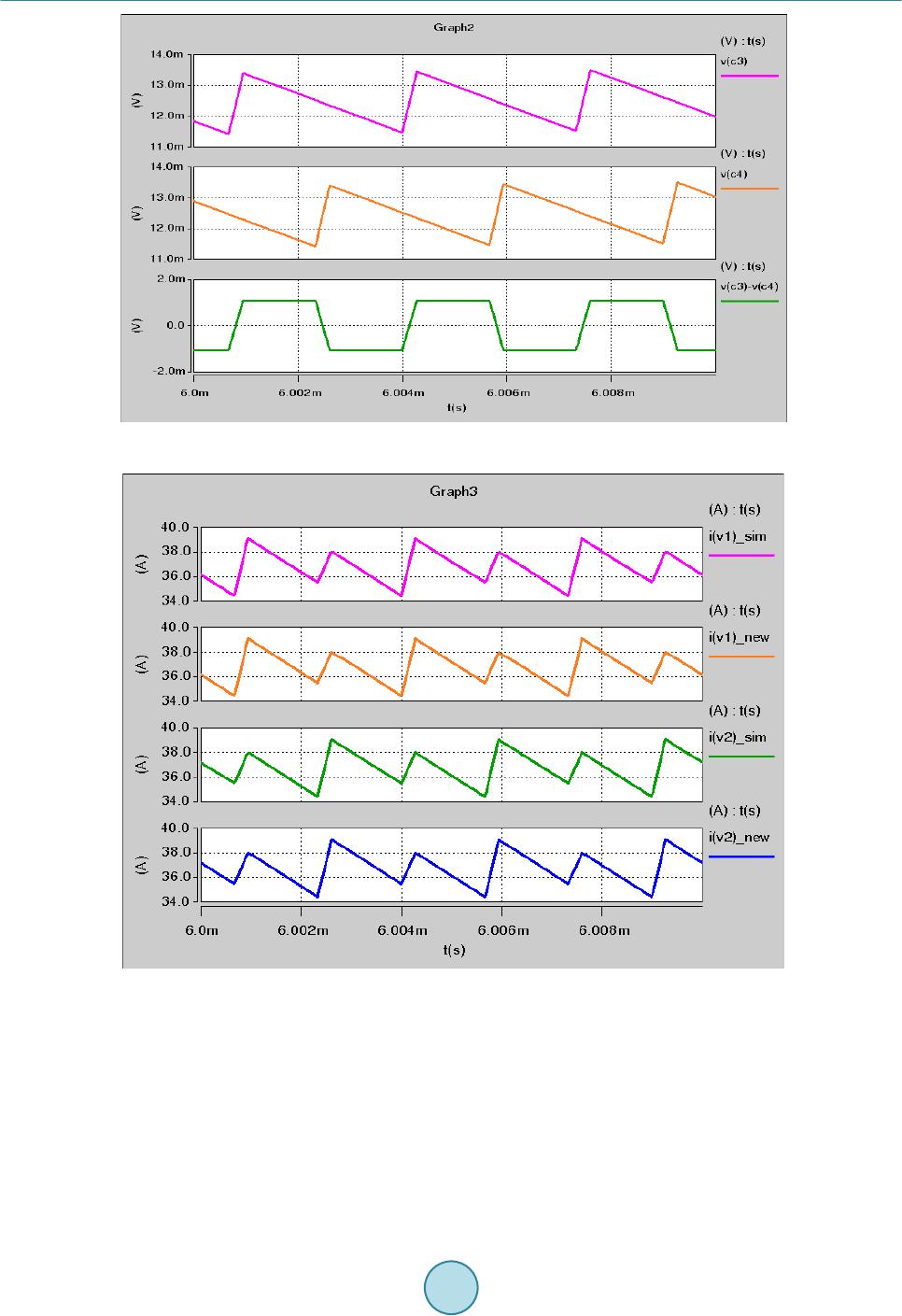 X. G. Liang, Y.-L. Li Figure 5. [C3 = C4 = 0.4 uF], v(c3), v(c4) and B(t) = v(c3) − v(c4) waveform. Figure 6. Probed phase current vs. derived phase current for couple inductor design. Input voltage: Vin = 12.6 V; Output voltage: Vo = 1 V; Coupling coefficient: k = 0; Self inductance: L = 1 uH; Individual Inductor DCR: RL = 1 mohm; Per-phase switching frequency: fsw = 300 kHz. Current sense network parameter is designed to satisfy (9) and (11): r1 = r2 = r3 = r4 = 4 kohm, C1 = C2 = C3 = C4 = 0.25 uF. For non-couple inductor design, two groups of sensing networks are identical, so Vc1 = Vc3, Vc2 = Vc4. Figure 7 shows derived A(t) and B(t) waveforms. Typically, non-couple inductor design only need one group DCR sensing network to get individual phase current since Vc1 and Vc2 could represent actual phase#1 and phase#2 current. Purpose here is just to verify the proposed method can also apply to non-couple inductor design. As shown in Fig ure 8, i(v1)sim and i(v2)si m are individual phase#1 and phase#2 current directly probed from 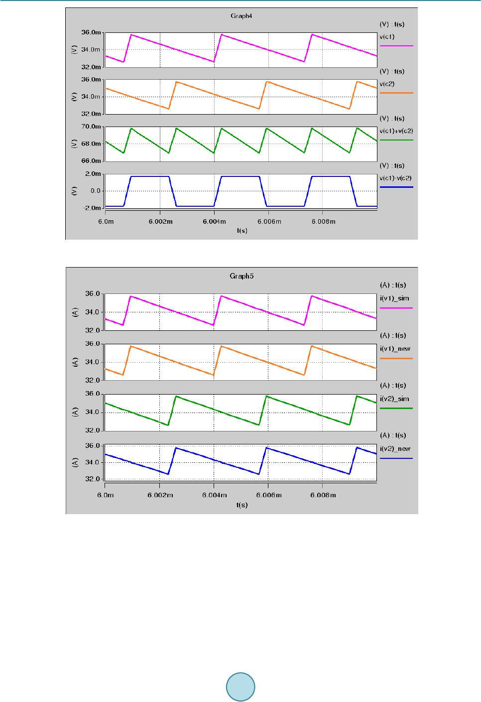 X. G. Liang, Y.-L. Li Fig ure 7. v(c1) = v(c3), v(c2) = v(c4), A(t) = v( c1) + v(c2) and B(t) = v(c1) − v(c2) waveform. Fig ure 8. Probed phase current vs. derived phase current for non-couple inductor design. inductors L1 and L2 in simulation circuit which is not feasible to test in practice; i(v1)new and i(v2)new are individual phase#1 and phase#2 current which is obtained by proposed method. Waveforms for phase#1 and phase#2 cur- rent are identical even they are obtained from different way, which verifies the proposed method can accurately predict individual phase current for non-couple inductor design as well 4. Conclusions One new method is proposed to losslessly sense individual phase current for couple inductor based interleaved multiphase VR design. Working principle is analyzed in detail and simulation is conducted to verify all theoreti-  X. G. Liang, Y.-L. Li cal analysis. It proves that this method is a universal way both for couple and non-couple inductor designs. Acknowledgements The author would like to acknowledge Jason Hu to help finish related simulation to acquire required data. References [1] Dong, Y., Su n, J.L., et al. (2007 ) The Light Load Issue of Coupled Inductor Laptop Voltage Regulators and Its Solu- tions. Proceeding s of 22 nd Annual IEEE Applied Power Electronics Conference, Anaheim, 25 Februar y-1 March 2007, 1581-1587. [2] Dong, Y., Lee, F.C. and Xu, M. (2008) Evaluation of Coupled Inductor Voltage Regulators. Proceedings of 23rd An- nual IEEE Applied Power Electronics Conference and Exposition, Austin, 24-28 Februa r y 2008, 831-837 . [3] Wu, W.K., Lee, N.-C. and Schuellein, G. (2006) Multi-Phase Buck Converter Design with T wo-Phase Coupled Induc- tors. Pro c eedings of 21st Annual IEEE Applied Power Electronics Conference and Exposition, 19-23 March 2006, 487-492. http://dx.doi.org/10.1109/APEC.2006.1620582 [4] Zhu, G.Y., McDonald, B.A. and Wang, K.R. (2009) Modeling and Analysis of Coupled Inductors in Power Converters. Proceedings of 24th Annual IEEE Applied Power Electronics Conference and Exposition, 15-19 February 2009, 83-89. http://dx.doi.org/10.1109/APEC.2009.4802637 [5] Zhu, G.Y. and Wang, K.R. (20 10) Modeling and Design Considerations of Coupled Inductor Converters. Proceedings of 25th Annual IEEE Applied Power Electronics Conference and Exposition, Palm Springs, 21-25 February 2010, 7-13. http://dx.doi.org/10.1109/APEC.2010.5433701
|