 Journal of Power and Energy Engineering, 2015, 3, 41-48 Published Online April 2015 in SciRes. http://www.scirp.org/journal/jpee http://dx.doi.org/10.4236/jpee.2015.34007 How to cite this paper: Zhou, S.J., Qiao, G.Y., He, C., Wang, W.H. and Liu, T.Q. (2015) Research on the Voltage Interaction of Multi-Infeed HVDC System and Interaction Factor. Journal of Power and Energy Engineering, 3, 41-48. http://dx.doi.org/10.4236/jpee.2015.34007 Research on the Voltage Interaction of Multi-Infeed HVDC System and Interaction Factor Shengjun Zhou1, Guangyao Qiao1, Chuan He2*, Wenhui Wang2, Tianqi Liu2 1State Grid Corporation, State Grid Smart Gird Research Institute, Beijing 102200, China 2School of Electrical Engineering and Information, Sichuan University, Chengdu 610065, China Email: *jokerscu@gmail.com Received Dec emb er 2014 Abstract In multi-infeed HVDC system, the interactions and influences between DC systems AC systems are complex as the electrical distances am o ng DC converter stations which are relatively short. Mul- ti-infeed interaction factor (MIIF) can effectively reflect the interaction amo ng DC systems. The paper theoretically analyzes the impact factors of MIIF like the electrical distances between two DC converter stations and the equivalent impedance of the receiving end AC system. By applying the Kirchhoff’s current law on the inverter AC bus, the paper deduces the analytical expressions for MIIF. From the expression, it is clear how the equivalent impedance of AC system and coupling impedance can affect MIIF. PSCAD simulations validate the effectiveness and the cor rectnes s of th e proposed expression and some useful conclusions are drawn. Keywords Multi-Infeed HVDC, Inverter Bus Voltage, Voltage Interaction, Interaction Factor, Equivalent Impedance, Coupling Impedance 1. Introduction With the increase of HVDC transmission lines, AC-DC parallel systems and the structure of multi-infeed DC systems will inevitably occur. A multi-infeed HVDC system is formed while inverter stations of a multi-ter- minal HVDC are connected to the same AC system [1]-[3]. For these types of systems, interactions among AC systems and DC systems can influence the characteristics of each other. The voltage interaction among inverter buses is a subject worthy of further study in a multi -infeed HVDC system. The characteristics of interactions in the multi-infeed HVDC system have great influence on the safe and stable operation of the whole power system [4] [5]. In-depth analysis of the relationship between the voltages of inverter station buses helps us to understand related problems. Multi-infeed interaction factor (MIIF) proposed by CIGRE working group WG B4-41 based on the definition  S. J. Zhou et al. of voltage interaction among converter stations is a very important indicator in multi-infeed HVDC systems [6] [7]. However, present methods of calculating the interaction factors are through simulations [8] [9]. The physi- cal meaning is unclear, and could not explain the internal reasons of interaction among subsystems. This makes the interaction factors lack of foresight [10], and unable to reflect the changes in the system structure and other influencing factors. Therefore, further studies on interactions among converter bus voltages and the analytical expressions of MIIF along with its influence to mult i -infeed HVDC system have important meanings. Reference [11] conducts a deep and detailed study on multi-terminal HVDC based on the multi-infeed short- circuit ratio defined by MIIF. Reference [12] gives the formula to calculate MIIF based on reduced Jacobian matrix of power flow, and also studies the effects of different DC system control methods on MIIF. In [13], the analytical expression of MIIF is derived by impedance matrix of system buses, and considers its influence on commutation failure. In [14], the relationship between MIIF and commutation failure is given through theoreti- cal analysis and proved by simulations. Furthermore, methods and criteria to quickly determine commutation failure are presented. However, for a large system, inverting the admittance matrix may require large number of computations. To overcome the drawbacks mentioned above, the paper analyzes the influences on MIIF like electrical dis- tances between two DC converter stations and the equivalent impedance of the receiving end AC system. And the analytical expression based on system admittance to calculate MIIF is deduced using Kirchhof f’s current law on the inverter AC bus. Theoretical analysis and PSCAD simulations of the analytical expression are given in an extended CIGRE standard HVDC system. 2. Multi-Infeed Interaction Factor Multi-infeed interaction factor (MIIF) was proposed by CIGRE WG B4 Working Group in 2008 as the working guide to measure the interactions among multi-infeed HVDC converter stations [6]. In the indicator, the voltage of inverter bus is chosen as a parameter because it mostly reflects the interaction. The definition of MIIF is: in- duce an approximate 1% step voltage at bus through the artificial switched connection of a shunt reac- tive element. Then observe the voltage change at bus which is shown in Figure 1. Equation (1) de- fines that the ratio of these two voltages is MIIF. (1) 2.1. Range of MIIF As it can be seen from the definition of MIIF, if two buses are infinitely far apart, then MIIF is 0. If two buses are connected to the same AC bus, MIIF equals 1. The range of MIIF is shown in Figure 2. 2.2. The Unsymmetrical Feature of MIIF Generally speaking, , and this will be proven in the next chapter. Large numbers of simulations indicate that the MIIF of a strong AC system to a weak AC system is high and the MIIF of weak AC system to a strong AC system is low. This is so because a 1% voltage drop in converter bus connected to a strong AC sys- tem can cause the voltage of nearby converter buses connected to weak AC systems to drop dramatically, hence Figure 1. Determining the MIIF between two buses.  S. J. Zhou et al. MIIF 01 Busses Infinitely Far Apart The Same Inverter Bus Figure 2. Range of MIIF. weak system,strong system MIIF is high. On the contrary, a 1% voltage drop in converter bus connected to a weak AC system will not influence the voltage of nearby converter buses connected to strong AC systems, hence strong system,weak system MIIF is low. 3. Analytical Expressions of MIIF In order to analyze MIIF of a multi-infeed HVDC system, the paper uses the simplified standard model, as shown in Figure 3. In Figure 3, denotes the effective value of AC power line voltage; denotes the equivalent reac- tance of AC systems; denotes the voltage of converter bus; denotes the ratio of converter transformer; denotes commutation reactance; denotes the line current flow to node in converter unit; denotes the capacitive reactance of reactive power compensation device at inverter buses. Define node as the reference node, and apply Kirch hoff ’s current law on the inverter bus N, we obtain: ( ) 12 1 nnLn fnNn nn IIIII I − +++ ++= (2) whe r e ()( ) 1 11 6 π nn Nn Nn nn nn nn Ln n n fn fn UE IX UU IX II U IX − − − − = − = = = − (3) Take Equation (3) into Equation (2), we get: ( ) 12 1 12 1 6 π nnnnn nn n nnfn Nn nn UUUUUUUUE I X XXXX − − −− −− ++++− = (4) Solve Equation (4 ), ( )( ) 1 1 12 12 12 11 61111 1 π nn nn Nn nnNn nnfn nn nn EU UU UI X XXXX XXXX − − −− =+ +++++ ++++ (5) Defi n e ( ) 12 1 11111 nn Nn nnfn nn YX XXXX − =+ ++++ as the self-admittance of bus N, then Equation (5) can be simplified as: ( ) ( ) 1 1 12 12 1 6 π nn nn nn Nn nnnn EU UU U IY X XXX − − − =+ ++++× (6) From Equation (6), it can be inferred that the voltage of bus j is:  S. J. Zhou et al. Figure 3. A multi-infeed HVDC system. ( )( ) ( ) 1 11 12 12 11 6 π j jj in jj jj Nj jjijnj jj jj E UU UU UU U IY XXXXX XX − −+ −+ =++++++++++× (7) Here we assume a voltage drop at bus i, and within a short time, the voltage of other buses do not change. Therefore, we obtain the voltage change at bus j: ( ) 1 1 1 6 π jii n jjj jj Nj jijnj EUU U U UU IY XX XX − +∆ +∆=+++++× (8) Subtract Equation (7 ) from Equation (8 ), we have, ( ) 1 i j jj ij U UY X − ∆ ∆= × (9) Rearrange Equation ( 9), we get, (10 ) where is the admittance between bus i and bus j, denotes the self-admittance of bus j. So the analytical expression of MIIF is as follows: (11) 4. Theoretical Analysis Take a dual-infeed HVDC system as example. In real systems, it is known that and . So the MIIF of bus 1 and bus 2 are simplified as Equations (12) and (13). 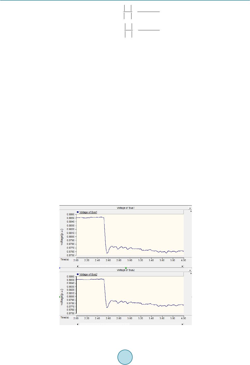 S. J. Zhou et al. 12 2 21 222 12 MIIF N N YX YXX = =+ (12) 12 1 12 111 12 MIIF N N YX YXX = = + (13) From Equation s (12) and (13), it can be seen that MIIF21 is basically not affected by XN1. However MIIF12 is greatly affected by XN1 where MIIF12 increases as XN1 increases. MIIF12 is not influenced by XN2 while MIIF21 is affected by XN2 where MIIF2 1 increases as X2 increases. Both MIIF21 and MIIF12 are influenced by X12 where they both decrease as X12 increases. We then extend the conclusion to multi-infeed HVDC system. MIIFji increases as the equivalent impedance of AC system corresponding to the jth converter station XNj increases. And that means if the equivalent impedance of its corresponding AC system is great, then the inverter bus voltage of this particular converter station can be greatly influenced by other converter stations. Moreover, the influence to this particular converter station by other converter stations increases as their electrical distance decreases. 5. Simulations Based on the CIGRE standard system, we in built a dual-infeed HVDC system. DC inverters are connected to each other through coupling impedance on the inverter buses while rectifiers are independent from each other as shown in Figure 1 The rectifiers use constant current control and inverters use constant extinction angle control. We adopt the initializing parameters of the system from [15] where the equivalent impedance of AC system is and the coupling impedance is . At 2.5 seconds, a three- phase shunt reactor is artificially switched in to cause the voltage of bus 1 to drop about 1%. In order to reduce the influence of ripple wave, we add a FFT module before bus voltages and use the DC output as the effective value of bus voltages. This is case 1 and simulation results are shown in Figure 4. From Figure 4, it can be seen that the voltage of bus 1 drops from 0.9852 p.u. to 0.9755 p.u. while the voltage of bus 2 drops from 0.9851 p.u. to 0.9767 p.u..The MIIF21 is calculated from Equation (1) to be 0.8660. Here we change the equivalent impedance of AC system connected to bus 2 to be , and calcu- late MIIF21. This is case 2. Then we introduce a three-phase shunt reactor at bus 2 to analyze the asymmetrical feature of MIIF. This is case 3. Simulation results of case 2 and case 3 are shown in Figure 5 and Figure 6 re- spectively. Figure 4. Voltage drops in bus 1 and bus 2 of case 1. 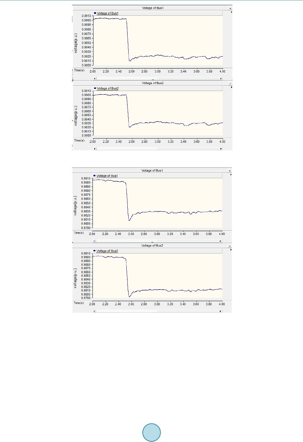 S. J. Zhou et al. Figure 5. Voltage drops in bus 1 and bus 2 of case 2. Figure 6. Voltage drops in bus 1 and bus 2 of case 3. Then based on the original state, we change the coupling impedance to be to analyze the variation of MIIF21. This is case 4 and result is shown in Figure 7. The simulation results and analytical results of MIIF21 with different AC system equivalent impedance z1, z2 and coupling impedance z12 are shown in Table 1. The simulation results and analytical results of MIIF12 are shown in Table 2. As it is shown in Table 1, Table 2 and Figures 4-7, the results of simulation and theoretical calculation are basically the same. MIIF21 increases as the coupling impedance decreases and decreases as the equivalent im- pedance of connected AC system decreases. Similarly, MIIF12 shows the same characteristic. The proposed me- thod to calculate MIIF has approximately 10% error compared to simulation result which can be concluded that it is a fast way to get a relatively accurate value of MIIF and has some worthiness to the study of multi-infeed 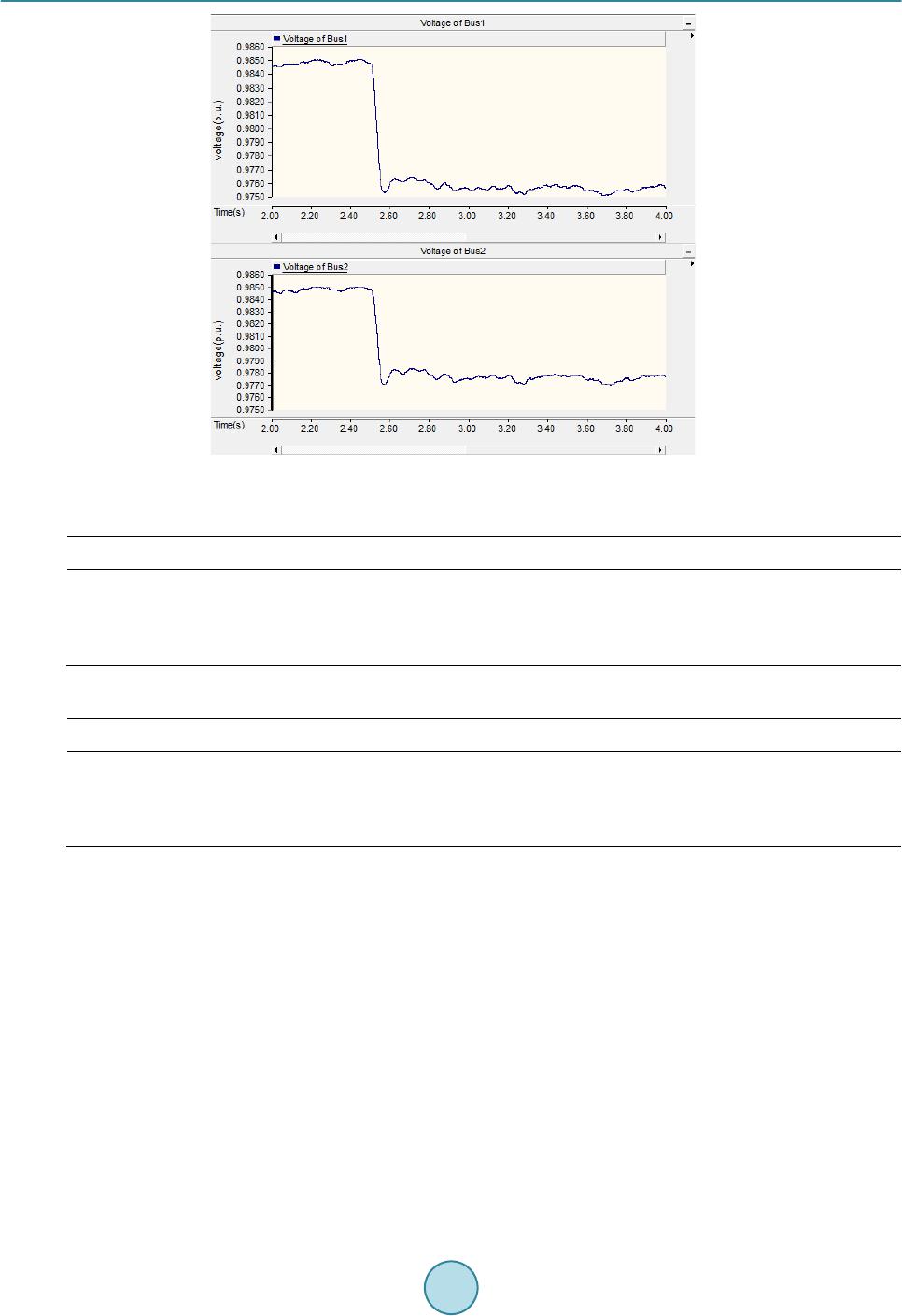 S. J. Zhou et al. Figure 7. Voltage drops in bus 1 and bus 2 of case 4. Table 1. Value of MIIF21 with different z1, z2 and z12. z1(Ω) z2(Ω) Z12(Ω) Simulation results analytical results 5.4984 + j20.466 5.4984 + j20.466 0.5 + j6.2832 0.8660 0.7730 5.4984 + j20.466 5 + j18 0.5 + j6.2832 0 .8468 0.7 503 5.4984 + j20.466 5.4984 + j20.466 0.75 + j9.4248 0.7780 0.6940 Table 2. Value of MIIF12 with different z1, z2 and z12. z1(Ω) z2(Ω) Z12(Ω) Simulation results analytical results 5.4984 + j20.466 5.4984 + j20.466 0.5 + j6.2832 0.8650 0.7730 5.4984 + j20.466 5 + j18 0.5 + j6.2832 0 .8642 0.7 730 5.4984 + j20.466 5.4984 + j20.466 0.75 + j9.4248 0.7405 0.6940 HVDC system. It should be noted that simulation results prove the symmetrical feature of MIIF which is when . 6. Conclusions The paper analyzes the voltage interactions among inverter buses in a multi-infeed HVDC system. By applying the Kirchhoff’s current law on the inverter AC bus, the paper deduces the analytical expression of the Multi-in- feed interaction factor. And some useful conclusions are drawn. MIIFji and MIIFij decrease as the coupling im- pedance increases, i.e. if converter station i and converter station j are electrically closeed, the interaction is strong. MIIFji decreases as the equivalent impedance of the connected AC system corresponding to converter station j decreases, i. e. if one converter station has great equivalent impedance of the connected AC system, it is likely to be greatly affected by other converter stations. Simulation results validate the accuracy and effectiveness of the proposed analytical expression of MIIF along with its theoretical analysis. It gives guidance and principle to improve the structure of power network and how to choose a good location of the receiving end of a new HVDC line.  S. J. Zhou et al. Acknowledgements This work is supported by Science and Technology Projects of State Grid Corporation (SGRIDL7114006). References [1] Yuan , X.F. and Cheng, S.J. (2006 ) Multi-Terminal HVDC Transmission Technology and Its Development. Relay, 34, 61-67. [2] Gu o, X.J., Ma, S.Y., Bu , G.Q., et al. (20 09 ) A Survey on Coordinated Control of Multi-Infeed HVDC Sys tem. Auto- mation of Electric Power Systems, 33, 9-15. [3] Tan g, G.F., Luo , X. and Wei, X.G. (2013) Mul ti -Terminal HVDC and DC-Grid Technology. Proceedings of the CSEE, 33, 8-17. [4] Sh ao, Y. and Tan g, Y. (2009) Current Situation of Research on Multi-Infeed AC/DC Power Systems. Power System Technology, 33, 24-30. [5] Yang, W.D., Xu , Z. and Han, Z.X. (2000) Special Issues and Suggestions on Mu lti -Infeed AC/DC Power Systems. Power System Technology, 24, 13-17. [6] CIGRE Working Group B4.41 (2008) Systems with Multiple DC Infe ed. CIGRE, P aris. [7] Nayak, R.N. and Sasmal, R.P. (2006) AC/DC Interactions in Multi -Infeed HVDC S cheme: A Case Study. IEEE Power Conferen ce, IEEE, Indi a, 5. [8] Wu , C., Li, X.Y. and He, C.R. (2007) Application of Multiinfeed Interaction Factor in South Grid Commutation Fail- ure Research. Rela y, 35, 26-31. [9] Li u , J., Li, X.Y., Fu, X.T., et al. (2009) Relationship of Multi -Infeed Short Circuit Ratio and Mu l ti -Infeed Interaction Factor with Commutation Failure. Power System Technology, 33, 20-25. [10] Jin, X.M., Zh ou , B.R., Gu a n, L., et al. (2009) HV DC-Interacti on-Strength Index for the Multi-Infee d -HVDC Power System. Automation of Electric Power System, 33, 98-102. [11] Guo, X.J., Guo, J.B., Ma, S.Y., et al. (2013) A Method for Multi DC Terminal Location Selection Based on Multi- Infeed Short Circuit Ratio. Proceedings of the CSEE, 33, 36-42. [12] Chen , X.Y., Han, M.X. and Liu , C.R. (2012) Impact of Control Modes on Voltage Interaction between Multi-Infeed AC-DC S yst e m. Automation of Electric Power Systems, 36, 58-63. [13] Shao , Y. and Tang, Y. (2012) A Commutation Failure Detection Method for HVDC Systems Based on Multi-Infeed Interaction Factors. Proceedings of the CSEE, 32, 108 -11 4. [14] Ra himi , E., Go l e , A.M., D avie s, J.B., et al. (2011) Commutation Failure Analysis in Multi-Infeed HVDC S yst ems. IEEE Transactions on Power Delivery, 26, 378 -38 4. http://dx.doi.org/10.1109/TPWRD.2010.2081692 [15] Xi ao, J. and Li, X.Y. (20 14) Analysis on Multi-Infeed Interaction Factor of Multi-Infeed AC/DC System and Multi- Terminal AC/DC System and Its Influencing Factor. Power System Technology, 38, 1-7. (In Chinese)
|