 Int. J. Communications, Network and System Sciences, 2015, 8, 85-90 Published Online April 2015 in SciRes. http://www.scirp.org/journal/ijcns http://dx.doi.org/10.4236/ijcns.2015.84011 How to cite this paper: Zhou, Q.L. (2015) The Study of Wireless Collision Avoidance and Early Warning System in Metro Ve- hicles. Int. J. Communications, Network and System Sciences, 8, 85-90. http://dx.doi.org/10.4236/ijcns.2015.84011 The Study of Wireless Collision Avoidance and Early Warning System in Metro Vehicles Qiaolian Zhou Technology Center, Shanghai Shentong Metro Group Co., Ltd., Shanghai, China Email: qiaolian_zhou@sina.com Received March 2015 Abstract The basic composition and working principle of wireless collision avoidance and early warning system based on spread spectrum ranging which is used in urban mass transit is introduced in this paper. Some performance indicators such as maximum measured distance and range errors are theoretically analyzed and numerically calculated. According to the characteristics of the urban mass transit, the applicability of the system is evaluated. Keywords Collision Avoidance and Early Warning, Spread Spectrum Ranging, Measured Distance, Range Errors 1. Introduction In recent years, with the rapid development of urban rail transit in China, the signal system is getting more at- tention as the key subsystem to ensure the safety of the train operation. According to the urban rail transit opera- tion data, the ATP removal events of urban rail transit signal system frequently occur. After the removal, the ve- hicle is controlled in manual mode, and the safety of operation is guaranteed by the driver. There is serious safety loophole in bad visual environment such as tunnel and curve. Once rear-end accident happens, it will cause casualties, property losses, traffic paralysis and other serious consequences. Thus, it is necessary to de- velop an independent wireless collision avoidance and early warning system while completing the ATP system [1]. Besides, the performance indicators such as maximum measured distance and range errors are evaluated. 2. System Architecture Shannon, the founder of the Information Theory, believes that the signal in the form of white noise is the best way to realize effective communication. The spread spectrum pseudo code wireless signal used in the wireless collision avoidance and early warning system is one of such signals. The train with this system can actively detect the co-directional train in the detection range by sending and receiving the spread spectrum signal. It also can calculate the distance between this train and the train ahead and give out acousto-optic alarm signal auto- matically when the detected distance is less than the preset safe distance. The ranging information can be the safety redundant information for the ATP to generate the over-speed protection curve when the ATP system is 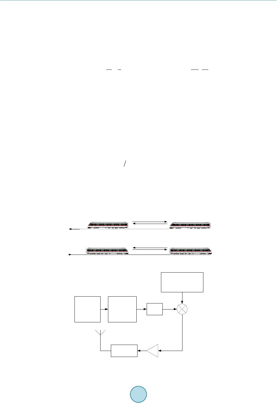 Q. L. Zhou normal. When the ATP fails, the operation safety in manual mode is guaranteed by the system. The ranging schematic is shown in Figure 1. The system is constituted by rangefinder and transponder which installed in both ends of the train. The system works as rangefinder when it installs in the front and transponder when in the rear. The rangefinder sends the spread spectrum pseudo code signal forward and the beam covers the scope about 30˚. The transponder of the front train receives the ranging signal and frequency conversion back forward the signal. Because the signal re- ceived by the rangefinder has a transmission delay compared to the original signal, the number of delayed code element and phase difference can be calculated [2]-[6]. The distance can be computed as () () 16 0 11 22 2 x xxx ct c sTNRNTP RPf ==− +−× (1) where is the distance between the two train; is the transmission rate of electromagnetic wave in the air; is the sending and receiving delay of rangefinder; is the PN code number of the sending signal which is recorded since it sends out; is the PN code number of the receiving signal which is recorded since it is recognized; is the 16 bit binary value of sending signal’s phase; is the 16 bit binary value of re- ceiving signal’s phase and is the code clock frequency of pseudo code. 2.1. The Rangefinder (1) The sending module of rangefinder The sending module of rangefinder is shown in Figure 2. The PN code which can be copied and has au- tocorrelation function is created by the pseudo code generating unit. Then it becomes to intermediate frequency digital phase-modulated signal by the digital modulation. After that, the D/A conversion module converts it into intermediate frequency analog signal. The ranging signal generates after the intermediate frequency sig- nal mixes with radio frequency local oscillator 1 and it is launched by the antenna after the smoothing. (2) The receiving module of rangefinder The receiving module of rangefinder is demonstrated in Figure 3. There is only the re-answer signal from the transponder left after the filtering. After low noise amplifying, down frequency conversion, filtering and ampli- fying, echo signal is generated. Besides, A/D sampling, multi-distance channel parallel correlation, constant false alarm target detection and decision are performed before outputting. Figure 1. The schematic diagram of ranging. Figure 2. The sending module of rangefinder. upgoing downgoing rangefinder transponder f 1 f 1 -Δf f 2 f 2 -Δf rangefinder transponder rangefindertransponder rangefindertransponder pseudo code generating unit BPSK digital modulation D/A filter antennapower amplifier radio frequency local oscillator 1 f1-Δf/f2-Δf 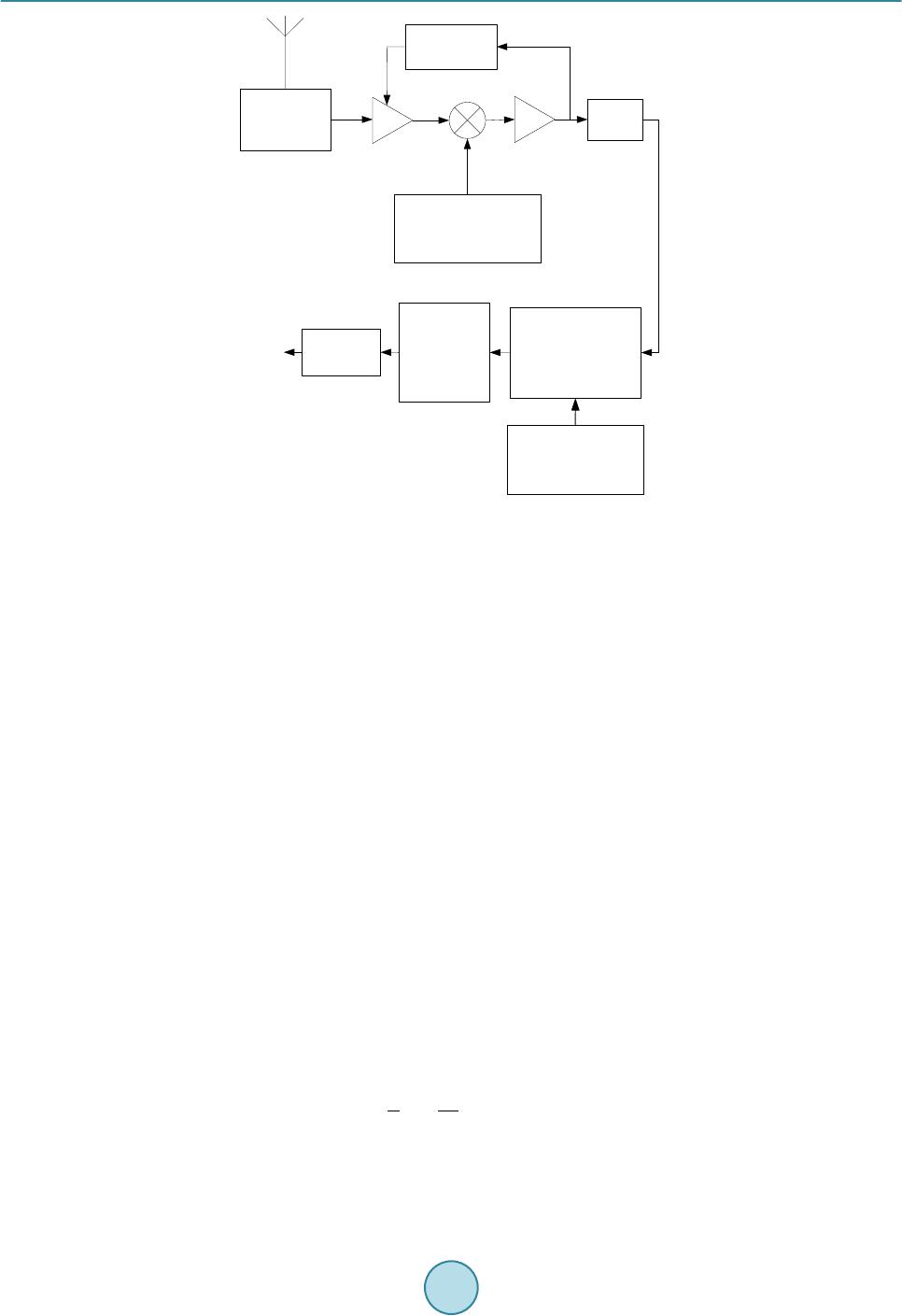 Q. L. Zhou Figure 3. The receiving module of rangefinder. 2.2. The Transponder As shown in Figure 4, the transponder receives the ranging signal of rangefinder by antenna. After low noise amplifying, down frequency conversion, filtering, we can get intermediate frequency signal. The forward signal generates after the intermediate frequency signal mixes with radio frequency local oscillator 2. Finally, it is launched by the antenna after the amplifying. 3. Performance Evaluation 3.1. Key Working Parameters (1) The receiving and sending frequency difference of rangefinder is 70 MHz. (2) Different frequencies are adopted for up-going and down-going trains to prevent mutual interference. For up-going trains, the frequency launched by rangefinder is 1505 MHz, launched by transponder is 1435 MHz. For down-going trains, the corresponding frequencies and are 1515 MHz and 1445 MHz. (3) The code clock frequency of the pseudo-random code is 1.023MHz, and the length p of the code se- quence is 1023. 3.2. Performance Analysis and Evaluation (1) The maximum measured distance The maximum unambiguous measured distance of the wireless collision avoidance and early warning system insure that the time delay between the sending signal and receiving signal of the rangefinder is less than one cycle of the pseudo code. It is derived as 5 max 0 11.510 m 2 p sc f = ××=× (2) where is the maximum unambiguous measured distance. The actual maximum measured distance of the system is less than , and it is presented as antenna filter LNA/AGC radio frequency local oscillator1 f 1 -Δf/f 2 -Δf A/D detector amplifier multi-distance channel Parallel correlative constant false alarm target detection target decision output pseudo code generating unit 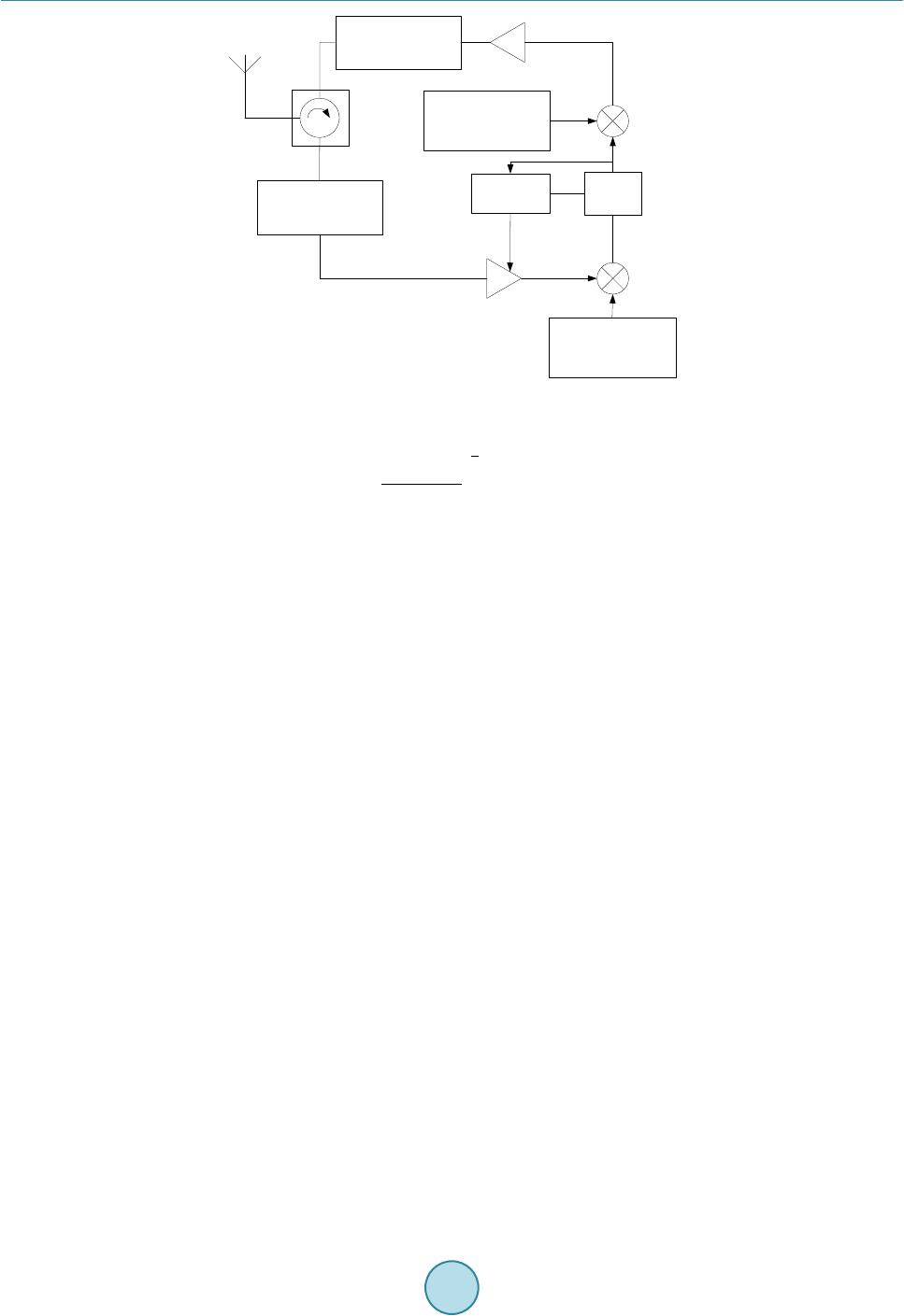 Q. L. Zhou Figure 4. The transponder. ( ) 1 4 22 max 3 min 600 m 4π t i PG lS λσ = ≈ (3 ) where is the maximum measured distance; is the transmitted power of the rangefinder; is the an- tenna gain; is the wave length; is the effective specula cross-section of the target and is the minimum detectable signal. Because there is two parameters and that is difficult to determine, the formula is always used to estimate the maximum distance. We estimate the value as 600 m by analysis and experiments. The wireless collision avoidance and early warning system is used in urban mass transit. It will output acous- to-optic alarm information when the measured distance is less than the preset one. The preset distance should greater than the driver reaction distance and emergency braking distance. Besides, the measured distance should greater than the preset distance. For the convenience of the calculation, simplify the brake process as two stages: the equivalent virtual braking stage and the active braking stage. The request distance is described as maxrea idl ac-br allo l llll ′= +++ (4 ) where is the minimum value of the maximum distance the system should reach; is the reaction dis- tance of the driver; is the equivalent virtual braking distance; is the active braking distance and allo is the safety allowance distance. To simplify the calculation, the length of the train is ignored, and it is thought to be a mass point. The train gets the maximum braking distance in the most disadvantage conditions. The conditions including that the mar- shalling of the train is the biggest, the train load is overloaded, the train is on the long heavy down grade, the train is not in the curve and tunnel, and the train begins to brake when it at the highest speed. To simplify the calculation of the reaction distance of the driver and the equivalent virtual braking distance, the running states of the train is regarded as uniform motion in the maximum speed. The two distances is simpli- fied as ( ) rea idlmaxrea idl 42.22 mllv tt+=× + = (5) where is the initial velocity of the train when it begins to brake, also the highest instantaneous velocity. is the react time of the driver and is the equivalent virtual braking time. The value of the here is 80 km/h. The react time of the driver includes the process of discovering the danger, making a judgment, and taking a brake. The value of the here is 1.5 s. The value of is 0.4 s, which is determined through specialized test and theory analysis [7]. antenna filter detector amplifier filter radio frequency local oscillator 2 f 1 -2Δf/f 2 -2Δf filter Radio frequency local oscillator 1 f 1 -Δf/f 2 -Δf LNA/AGC  Q. L. Zhou When the train is in the emergency brake, the resultant force is the composition of braking force, datum resis- tance and additional resistance, so the accelerated speed is a variable quantity. When the movement of the train is treated as uniformly retarded motion, the active braking distance can be counted as 2 max ac-br 2146.10 m 2 v la = = × (6 ) The average emergency braking deceleration of Shanghai urban rail transit should not less than 1.3 m/s2, the value here is 1.3 m/s2. In consideration of the complicated factors such as range errors, the safety allowance distance is 50 m. The train emergency braking distance at the initial velocity of 80 km/h is about 238.32 m. Thus there is enough time for driver to take action after the system detects the front train which has a security threat and puts out acousto- optic alarm signals. (2) Range errors The errors of pseudo range measurement depend on the interaction of intricate factors. The phase measuring quantization error, the random error introduced by the thermal noise, the delay error of the receiving module of rangefinder composes the main body of the measure errors when the multipath and other distractions are ignored [8]. a) The phase measuring quantization error In the spread spectrum ranging system, the signal phase measuring error represents the distinguish ability of the system. The system adopts 16-bit phase accumulator DDS to generate code clock, so the distinguish ability is one over sixteen of a code element [9] [10]. The phase measuring quantization error is given as 3 16 0 11 2.2410 m 22 s rc f σ − = ××=× × (7) The phase measuring quantization error is millimeter-sized, so it can be ignored. b) The random error introduced by the thermal noise The mean square ranging error of code phase jitter introduced by the thermal noise is expressed as _DLL DLL DLL 00 2 12.63 m 2 n t B CC T NN σ =+= (8) where is carrier to noise ratio; is loop noise bandwidth and is the time of coherent integra- tion. c) The delay error of the receiving module of rangefinder Generally speaking, receive delay can be taken as Δtd = 3/B, in which B is the receiver bandwidth. This is a fixed delay. If the receiver bandwidth is 5 MHz, the residual error after compensation and correction can be calculated as (9) where is the delay error of the receiving module of rangefinder and B is the bandwidth of the receiving module of rangefinder. We assume that all kinds of error components have the equal weights, the total distance-measuring error of the system is expressed as 22 2 DLL 3.30 m r stt rr σ σσσ =+ +≈ (10) The wireless collision avoidance and early warning system is not like the satellite telemetry and telecontrol system which has the very high accuracy requirements. The collision avoidance system has enough safety al- lowance to avoid the train collision, so the distance measuring error demand is as low as 10 m. It is obviously that the system can satisfy the early warning demand in the aspect of precision.  Q. L. Zhou 4. Conclusion The basic composition and working principle of wireless collision avoidance and early warning system is briefly introduced in this paper. By analyzing of the significant parameters, we draw a conclusion that both the maxi- mum measured distance and range accuracy can satisfy the early warning demand of the urban mass transit. The system can provide a good reference for the research and development of the train collision avoidance technol- ogy. Acknowledgements This work is supported by the Shanghai Committee of Science and Technology, China (12231200103). The au- thor is grateful for the reviewer of initial drafts for their helpful comments and suggestions. References [1] Lin, J.T., Dang, J.W., Cao, Y. and Dong, D.C. (2012) Analysis of Collision Avoidance System and Application Design for Railway Transportation. Application of Electronic Technique, 38, 63-66. [2] Chen, S.J. (2003) The Research of High Precision Distance Measurement Method. Radio Engineering, 33, 22-23. [3] Xia, J. (2010) Pseudo Code Ranging Method and Precision Analysis of GPS Receiver. Telecommunication Engineer- ing, 50, 26-29. [4] Kaplan, E.D. (2007) Understanding GPS Principles and Applications. Publishing House of Electronics Industry, 14-18. [5] Chen, L., Ren, Z. and Xia, J. (2001) Synthetical Basedband Remote Cell Signal Synchronous Realization. Telecommu- nication Engineering, 41, 16-18. [6] Zhang, Y.Q. (2008) Research on Spread Spectrum Ranging System. Master Thesis, Harbin University of Science and Technology. [7] Ma, X.C. (2007) Analysis and Calculation on the Emergency Braking Function of Metro Vehicles for Shanghai Rail Transit Line 4. Electric Locomotives & Mass Transit Vehicles, 30, 27-30. [8] Ding, L.F., Geng, F.L. and Chen, J.C. (2009) Principles of Radar. 4th Edition, Publishing House of Electronics Indus- try, 219-220. [9] Tang, J., Xie, S.L. and Wang, W.X. (2004) Pseudo Code Ranging Method and Precision Analysis of Aerospace Spread Spectrum TCC&DT Systems. Research & Development, 4, 91-95. [10] Guo, Q. and Zeng, H.B. (2003) The Analysis of Pseudo Noise Code Ranging in Satellite TT&C. Communications Technology, 10, 41-43.
|