Journal of Encapsulation and Adsorption Sciences, 2011, 1, 29-34
doi:10.4236/jeas.2011.11004 Published Online June 2011 (http://www.scirp.org/journal/jeas)
Copyright © 2011 SciRes. JEAS
Production of Carbon Nanotubes by Different Routes—
A Review
Muhammad Musaddique Ali Rafique*, Javed Iqbal
Departme n t of Metal lurgical & Materi als Engineeri ng, University of Engineering & Technology, Lahore, Pakistan
E-mail: 2001met1340@student.uet.edu.pk
Received April 27, 2011; revised May 21, 2011; accepted May 29, 2011
Abstract
Carbon Nanotubes are one the most important materials of future. Discovered in 1991, they have reached a
stage of attracting the interests of many companies world wide for their large scale production. They possess
remarkable electrical, mechanical, optical, thermal and chemical properties, which make them a perfect “fit”
for many engineering applications. In this paper various methods of production of carbon nanotubes are dis-
cussed outlining their capabilities, efficiencies and possible exploitation as economic large scale production
methods. Chemical vapor disposition (CVD) is proposed as a potential method for economic large scale
production of carbon nanotubes due to its relative simplicity of operation, process control, energy efficiency,
raw materials used, capability to scale up as large unit operation, high yield and purity.
Keywords: Carbon Nanotubes, Chemical Vapor Deposition (CVD), Unit Operation, Yield
1. Introduction
Carbon nanotubes (CNTs) are allotropes of carbon. A
carbon nanotube is a one-atom thick sheet of graphite
(called graphene) rolled up into a seamless cylinder with
diameter of the order of a nanometer. This results in a
nanostructure where the length-to-diameter ratio exceeds
10,000. Such cylindrical carbon molecules have novel
properties that make them potentially useful in a wide
variety of applications in mechanical, structural, thermal,
electrical & electronics, optical, biomedical and other
fields of science, engineering & medicine. They exhibit
extraordinary strength and unique electrical properties,
and are efficient conductors of heat. Their name is de-
rived from their size, since the diameter of a nanotube is
on the order of a few nanometers (approximately 50,000
times smaller than the width of a human hair), while they
can be up to several millimeters in length. [1,2].
Though discovered far earlier [3-5], first noticeable
discovery of carbon n anotubes was reported by Ilij ima [6]
in 1991, when he found layers of car bo (graphene) rolled
into tubular structure in the soot of arc dischage method.
The nanotubes consisted of up to several tens of graphitic
shells (so called multi-walled carbon nanotubes
(MWNT)) with adjacent shell separation of 0.34 nm,
diameters of 1 nm and high length/diameter ratio. Ili-
jima’s discovery of carbon nanotubes in the insoluble
material of arc-burned graphite rods created the buzz that
greatly accelerated work on synthesis, production and
properties of carbon nanotubes. It took two more years
for Iijima and Ichihashi at NEC [7], and Bethune et al. [8]
at IBM to synthesize SWNT by addition of transition
metal catalysts to carbon in an arc discharge in 1993.
Significant contributions to the race for devising method
for production of carbon nanotubes were made by la-
ser-ablation synthesis of bundles of aligned SWNT with
small diameter distribution by Smalley and co- workers
at Rice University in 1995 [9] and by catalytic growth of
nanotubes by the chemical vapor decomposition (CVD)
method by Yacaman et al. [10].
There are two main types of carbon nanotubes [11]
that can have high structural perfection. Single walled
nanotubes (SWNT), these consist of a single graphite
sheet seamlessly wrapped into a cylindrical tube. Multi
walled nanotubes (MWNT), these comprise an array of
nanotubes one concentrically placed inside another like
rings of a tree trunk.
2. Production of Carbon Nanotubes
There are various methods of production of carbon nano-
tubes such as production of nanotubes by arc discharge,
chemical vapor deposition, laser ablation, flame synthesis,
high pressure carbon monoxide (HiPco), electrolysis,
M. M. A. RAFIQUE ET AL.
30
pyrolysis etc. But they can be mainly classified into fol-
lowing groups.
1) Physical Processes
2) Chemical Processes
3) Miscellaneous Processes
2.1. Physical Processes
These are the processes, which make use of physical
principles of carbon conversion into nanotubes. These
include popular process of carbon nanotubes production
such as arc discharge and laser ablation. Due to their
wide spread popularity they are by far the most widely
used processes for nanotubes production for experimen-
tal purposes.
2.1.1. Ar c Discharg e
This is one of the oldest methods of carbon nanotube
production. First utilized by Iijima [6] in 1991 at NEC’s
Fundamental Research Laboratory to produce new type
of finite carbon structures consisting of needle-like tubes.
The tubes were produced using an arc discharge evapo-
ration method similar to that used for the fullerene syn-
thesis. The carbon needles, ranging from 4 to 30 nm in
diameter and up to 1 mm in length, were grown on the
negative end of the carbon electrode used for the direct
current (DC) arc-discharge evaporation of carbon. Dur-
ing the process Iijima used a pressurized chamber filled
with a gas mixture of 10 Torr methane and 40 Torr argon.
Two vertical thin electrodes were installed in the center
of the chamber (Figure 1). The lower electrode (cathode)
contained a small piece of iron in a shallow dip made
purposefully to hold iron.
Figure 1. Arc discharge method for CNT.
The arf 200 A
at
.1.2. Laser Ablation Process pulsed laser is made to
lly and
Co
c was generated by running a DC current o
20 V between the electrodes. The use of the three
components, namely argon, iron and methane, was criti-
cal for the synthesis of SWNT. Carbon soot produced as
result of arc-discharge settled and nano tubes grew on the
iron catalysts contained in negative cathode. The nano-
tubes had diameters of 1 nm with a broad diameter dis-
tribution between 0.7 and 1.65 nm. In a similar process
Bethune et al. used thin electrodes with bored holes as
anodes, which were filled with a mixture of pure pow-
dered metals (Fe, Ni or Co) (catalysts) and graphite. The
electrodes were vaporized with a current of 95 - 105 A in
100 - 500 Torr of Helium. SWNT were also produced by
the variant of arc-technique by Journet et al. [12] as well.
In his variant, the arc was generated between two graph-
ite electrodes in a reaction chamber under helium at-
mosphere (660 mbar). Th is method also gave large yield
of carbon nanotubes. Ebbesen and Ajayan, [13] however,
reported large-scale synthesis of MWNT by a variant of
the standard arc discharge technique as well.
2
In the laser ablation process, a
strike at graphite target in a high temperature reactor in
the presence of inert gas such as helium which vaporizes
a graphite target. The nanotubes develop on the cooler
surfaces of the reactor, as the vaporized carbon condenses.
A water-cooled surface is also included in the most prac-
tical systems to collect the nanotubes (Figure 2).
This method was first discovered by Sma
-workers at Rive University in 1995 [9]. At the time
of discovery they were studying the effect of laser
impingment on metals. They produced high yields
(>70%) of Single walled Carbon Nanotubes by laser ab-
lation of graphite rods containing small amounts of Ni
and Co at 1200˚C. In this method two-step laser ab lation
was used. Initial laser vaporization pulse was followed
by second pulse to vaporise target more rapidly. The two
step process minimizes the amount of carbon deposited
as soot. Tubes grow in this method on catalysts atoms
Figure 2. Schematic of laser ablation method for carbon
nanotube production.
Copyright © 2011 SciRes. JEAS
M. M. A. RAFIQUE ET AL.31
until to many catalyst atoms ag-
.1.3. Disadvantages of Arc-Discharge and Laser
Both ge and laser ablation produces some of
energy extensive methods-a large
am
s require solid carbon/graphite as tar-
ge
cesses grow nanotubes in highly tangled
fo
of
2.2 Chemical Processes
2. 1. Chemical Vap or Dep osi tion merged as potential
e substrate is
on
ma assisted CVD” is
a
2.2. High Pressure Carbon Monoxide Reaction
This isethod developed at Rice University in
.2.3 Co MoCAT® Process de at University of Okla-
and continued to grow
gregate at the end of the tube. The tubes produced by this
method are in the form of mat of ropes 10 - 20 nm in
diameter and up to 100 micron or more in length. By
varying temperature, catalyst composition and other
process parameters average diameter and length of car-
bon naotube could be varied.
2Ablation
arc-dischar
the most high quality nanotube s but suffers from follow-
ing disadvantages which limit their use as large scale
industrial processes.
1) They both are
ount of energy is needed to produce arc or laser used
for ablation processes. Such a huge amount of energy is
not only impossible but also uneconomical for large
scale production.
2) Both method
t which has to be evaporated to get nanotubes. It is
difficult to get such larg e graphite to be used as target in
industrial process which limits its exploitation as large
scale process.
3) Both pro
rm, mixed with unwanted form of carbon or catlysts.
Thus CNTs produced by these processes require purifi-
cation to get purified and assembled forms. The design-
ing of such refining processes is difficult and expensive.
All the above mentioned factors severely limit the use
both arc-discharge and laser ablation as large scale
processes for production of carbon na notubes.
2.
In 1996 Chemical vapor deposition e
method for large scale production and synthesis of car-
bon nanotubes. This method is capable of controlling
growth directions on a substrate and synthesizing a large
quantity of carbon nanotubes [14]. In this process a mix-
ture of hydrocarbon gas (ethylene, methane or acetylene)
and a process gas (ammonia, nitrogen, hydrogen) is
made to react in a reaction chamber on heated metal sub-
strate at temperature of around 700˚C - 900˚C, at atmos-
pheric pressures. CNTs formed as a result of decomposi-
tion of hydrocarbon gas and deposit and grow on metal
catalyst (substrate). The catalysts particle can stay at the
bottom or top of growing carbon nanotube.
The use of the catalyst and preparation of th
e of the most important factors in CVD, as this substrate
will define the nature and type of carbon nanotubes formed.
The usually substrate material is silicon, but glass and alu-
mina are also used. The catalysts are metal nanoparticles,
like Fe, Co and Ni, which can be deposited on substrates by
means of electron beam evaporation, physical sputtering or
solution deposition. Porous silicon is an ideal substrate for
growing self-oriented nanotubes on large surfaces. The
nanotube diameter depends on the catalyst particle size,
therefore, the catalyst deposition technique should be cho-
sen carefully to yield desired results.
A variant of CVD known as “plas
process in which a plasma is generated during the
process. By properly adjusting the geometry of reactor
during plasma assisted CVD, it is possible to grow verti-
cally grown carbon naotubes. Without plasma carbon
nanotubes produced are usually random gropus just like
bowl of spaghetti. However, under certain carefully con-
trolled conditions even in the absence of plasma verti-
cally alighned carbon nanotubes resembling that of forst
or carpet can be produced. Recently at University of
Califfornia, Berkeley [15] researchers have also reported
the production of double walled carbon nanotubes from
CVD. Similar success has also been reported at Univer-
sity of California, San Diago [1 6].
2. (HiPco®)
a unique m
1999 for the production of carbon nanotubes [17]. Unlike
other methods in which the metal catalysts are deposited
or embedded on the substrate before the deposition of the
carbon begins, in this method catalyst is introduced in
gas phase. Both the catalyst and the hydrocarbon g as are
fed into a furnace, followed by catalytic reaction in the
gas phase. This method is suitable for large-scale synthe-
sis, because the nanotubes are free from catalytic sup-
ports and the reaction can be operated continuously.
Usually CO gas is used as hydrocarbon gas which reacts
with iron pentacarbonyl, Fe(CO)5 to form SWNT. This
process is called HiPco process. SWNT have also been
synthesized in a variant of HiPco process in which a
mixture of benzene and ferrocene, Fe(C5H5)2 reacts in a
hydrogen gas flow to form SWNT [18]. In both methods,
catalyst nanoparticles are formed through thermal de-
composition of organometallic compounds, such as iron
pentacarbon yl and ferrocene.
2
Recently an effort has been ma
homa [19], to develop a process using Cobalt and Molyb-
denum catalysts and CO gases. In this method, SWNT are
grown by CO disproportionation (decomposition into C
and CO2) in the presence of CoMo Catalyst (specifically
developed for the purpose) at 700˚C - 950˚C in flow of
pure CO at a total pressure that typically ranges from 1 to
Copyright © 2011 SciRes. JEAS
M. M. A. RAFIQUE ET AL.
32
.2.4. Advantage s of C hemical Processes pared to
reactor design is simple, reac-
tio vailable readily in
th of expensive and difficult to pro-
du
ucing CNTs directly onto
su
e production of vertically
al
designed for continuous operation
(H
more research is underway in the world to-
da
ac
.3 Miscellaneous Processes
ome miscellaneous and relatively less used pro cesses of
.3.1 Heli u m Arc Disch a rge Method SA’s Goddard
e as
co
.3.2. Electrolysis on nanotubes were produced at Uni-
2.3 Flame Synthesis n the synthesis of SWNT in a
lly burned to
10 atm. This process is able to grow a significant amount
of SWNT (about 0.25 g SWNT/g catalyst) in a couple of
hours, keeping selectivity towards SWNT better than 80%.
The secret of the process is in synergistic effect of Co and
Mo. Catalyst is most effective when both metals Co and
Mo are present at a time on silica substrate with low
Co:Mo ratio. The material produced by the HiPco process
yields a much larger number of bands, which indicate a
greater variety of diameters than the material produced by
CoMoCAT Process. The distribution of diameters pro-
duced by the HiPco process reported in the literature is
also significantly broader than that of the product obtained
from the CoMoCAT process. This process carries strong
prospects in it to be scaled up as large scale production
process for the production of SWNT.
2
These methods have many advantages as com
forem e ntioned pr o ce ss es.
1) Reaction process and
n is easy to control and manipulate.
2) Raw materials are abundant and a
e form of gases.
3) Due to absence
ce targets and huge amount of energy needed, process
is cheap in terms of unit price.
4) Process is capable of prod
bstrates which ease out the process of further collec-
tion and separation and eliminates post refining proc-
esses to a large extent. Some refining is requ ired in some
cases for further purification.
5) Process is unique for th
ighned nanotubes. No other process can produce
alighned nano tubes .
f. Process can be
iPco) and easily scaled up to large industrial process
due to its nature of operation similar to chemical unit
operations.
More and
y for the production of large quantities of high purity
carbon nanotubes by chemi cal vapor depos ition process.
Researchers are developing method and designing re-
tors, which could be utilized as units for large scale
productio n of c arbon nanotube s.
2
S
carbon nan otube prod uction are gi v en below.
2
It was reported in 200 6 by scientists of NA
Space Flight Center that they have developed a simple,
safe, and very economical process of Single walled car-
bon nanotubes production [20]. In this method scientists
used a helium arc welding process to vaporize an amor-
phous carbon rod and then form nanotubes by depo siting
the vapor onto a water-cooled carbon cathode. This
process yields bundles, or “ropes,” of single-walled
nanotubes at a rate of 2 grams per hour using a single
setup. I was claimed that process would produce
SWCNT with yield of 70% at a much lower cost as
compared to previously achieved yield of 30% - 50% at a
cost of approximately $100 per gram. Further it was
claimed, as process does not require any metal catalyst
no metal particles need to be removed from the final
product. Eliminating the presence of metallic impurities
results in the SWCNTs exhibiting higher degradation
temperatures (650˚C rather than 500˚C) and eliminates
damage to the SWCNTs by t he pu rifi cat i o n pr ocess.
This process is under discussion for potential us
mmercial scale process.
2
In this method carb
versity of Miskolc by G. Kaptay & J. Sytchev [21] by de-
positing alkali metals on a graphite cathode from a
high-temperature molten salt system. The deposited metal-
lic atoms intercalate into the space between the graphitic
sheets and diffuse towards the bulk of the graphite cathode,
causing some mechanical stress inside graphite. This stress
induces the ablation of separate graphitic sheets, which
will turn into carbon nanotubes due to interfacial forces,
trying to recombine broken carbon-carbon bonds. Though
this method has been reported to yield good quality of
carbon nanotubes. It is not scaleable to large scale produc-
tion method t o produce carbon nanotubes.
3.
This method is based o
controlled flame environment, that produces the tem-
perature, forms the carbon atoms from the inexpensive
hydrocarbon fuels and forms small aerosol metal catalyst
islands [22,23]. SWNT are grown on these metal island s
in the same manner as in laser ablation and arc discharge.
These metal catalyst islands can be made in three ways.
The metal catalyst (cobalt) can either be coated on a
mesh [22], on which metal islands resembling droplets
were formed by physical vapor deposition. These small
islands become aerosol after exposure to a flame. The
second way is to create aerosol small metal particles by
burning a filter paper that is rinsed with a metal-ion (e.g.
iron nitrate) solution. The third way is the thermal
evaporating technique in which metal powder (e.g. Fe or
Ni) is inserted in a trough and heated [23].
In a controlled way a fuel gas is partia
Copyright © 2011 SciRes. JEAS
M. M. A. RAFIQUE ET AL.33
ga
. Comparison
elow a comparison of three most widely used meth-
. Conclusions
ollowing conclusion can be drawn from above discus-
arc-discharge and laser ablation methods suf-
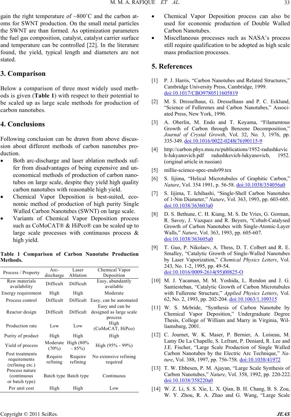
able 1 Comparison of Carbon Nanotube Production
operty Arc-
die Laser
A Chemical Vapor
in the right temperature of ~800˚C and the carbon at-
oms for SWNT production. On the small metal particles
the SWNT are than formed. As optimization parameters
the fuel gas composition, catalyst, catalyst carrier surface
and temperature can be controlled [22]. In the literature
found, the yield, typical length and diameters are not
stated.
3
B
ods is given (Table 1) with respect to their poten tial to
be scaled up as large scale methods for production of
carbon nanotubes.
4
F
sion about different methods of carbon nanotubes pro-
duction.
Both
fer from disadvantages of being expensive and un-
economical methods of production of carbon nano-
tubes on large scale, despite they yield high quality
carbon nanotubes with reasonable high yield.
Chemical Vapor Deposition is best-suited,eco-
nomic method of production of high purity Single
Walled Carbon Nanotubes (SWNT) on large scale.
Variants of Chemical Vapor Deposition process
such as CoMoCAT® & HiPco® can be scaled up to
large scale processes with continuous process &
high yield.
T
Methods.
Process / Prscharg blation Deposition
Raw materials
availab ili ty Difficult Difficult Easy, abundantly
available
Ennt
D D Easy, ated
Production rate Low Low (CoMo iPco)
MHi High 99%)
No exte
Batch type Batch type Continuous
High High Low
eergy requiremHigh High Moderate
Process control ifficultifficultcan be autom
Reactor design Difficult Difficult Easy and can be
des igned as l arg e s cal e
process
High
CAT, H
Purity of product High High High
Yield of process oderate
(70%) gh (80%
- 85%)
Require
(95% -
Post treatments
requirements
(refining etc.)
Require
refining refining nsive refining
required
Process nature
(continuous
or batch type)
Per unit cost
Chemical Vapor Deposition process can also be
used for economic production of Double Walled
Carbon Nanotubes.
Miscellaneous processes such as NASA’s process
still require qualification to be adop ted as high scale
mass production processes.
5. References
[1] P. J. Harris, “Carbon Nanotubes and Related Structures,”
Cambridge University Press, Cambridge, 1999.
doi:10.1017/CBO9780511605819
[2] M. S. Dresselhaus, G. Dresselhaus and P. C. Ecklund,
“Science of Fullerenes and Carbon Nanotubes,” Associ-
ated Press, New York, 1996.
[3] A. Oberlin, M. Endo and T. Koyama, “Filamentous
Growth of Carbon through Benzene Decomposition,”
Journal of Crystal Growth, Vol. 32, No. 3, 1976, pp.
335-349. doi:10.1016/0022-0248(76)90115-9
[4] http://carbon.phys.msu.ru/publications/1952-radushkevic
h-lukyanovich.pdf radushkevich-lukyanovich, 1952.
(original article in russian)
[5] millie-science-spec-endo99.tex
[6] S. Iijima, “Helical Microtubules of Graphitic Carbon,”
Nature, Vol. 354 1991, p. 56-58. doi:10.1038/354056a0
[7] S. Iijima, T. Ichihashi, “Single-Shell Carbon Nanotubes
of 1-Nm Diameter,” Nature, Vol. 363, 1993, pp. 603-605.
doi:10.1038/363603a0
[8] D. S. Bethune, C. H. Kiang, M. S. De Vries, G. Gorman,
R. Savoy, J. Vazquez and R. Beyers, “Cobalt-Catalysed
Growth of Carbon Nanotubes with Single-Atomic-Layer
Walls,” Nature, Vol. 363, 1993, pp. 605-607.
doi:10.1038/363605a0
[9] T. Guo, P. Nikolaev, A. Thess, D. T. Colbert and R. E.
Smalley, “Catalytic Growth of Single-Walled Nanotubes
by Laser Vaporization,” Chemical Physics Letters, Vol.
243, No. 1-2, 1995, pp. 49-54.
doi:10.1016/0009-2614(95)00825-O
[10] M. J. Yacaman, M. M. Yoshida, L. Rendon and J. G.
Santiesteban, “Catalytic Growth of Carbon Microtubules
with Fullerene Structure,” Applied Physics Letters, Vol.
62, No. 2, 1993, pp. 202-204. doi:10.1063/1.109315
[11] W. S. Mcbride, “Synthesis of Carbon Nanotube by
Chemical Vapor Deposition,” Undergraduate Degree
Thesis, College of William and Marry in Virginia, Wil-
liamsburg, 2001.
[12] C. Journet, W. K. Maser, P. Bernier, A. Loiseau, M.
Lamy De La Chapelle, S. Lefrant, P. Deniard, R. Lee and
J.E. Fischer, “Large Scale Production of Single Walled
Carbon Nanotubes by the Electric Arc Technique,” Na-
ture, Vol. 388, 1997, pp. 756-758. doi:10.1038/41972
[13] T. W. Ebbesen, P. M. Ajayan, “Large Scale Synthesis of
Carbon Nanotubes,” Nature, Vol. 358, 1992, pp. 220-222.
doi:10.1038/358220a0
[14] W. Z. Li, S. S. Xie, L. X. Qian, B. H. Chang, B. S. Zou,
W. Y. Zhou, R. A. Zhao and G. Wang, “Large Scale
Copyright © 2011 SciRes. JEAS
M. M. A. RAFIQUE ET AL.
Copyright © 2011 SciRes. JEAS
34
Synthesis of Aligned Carbon Nanotubes,” Science, Vol.
274, No. 5293, 1996, pp. 1701-1703.
doi:10.1126/science.274.5293.1701
[15] J. Cumings, W. Mickelson and A. Zettl, “Simplified Syn-
thesis of Double Wall Carbon Nanotubes,” Solid State
Communications, Vol. 126, No. 6, 2003, pp. 359-362.
doi:10.1016/S0038-1098(02)00881-5
[16] C. P. Deck, G. S. B. Mckee and K. S. Vecchio, “Synthe-
sis Optimization & Characterization of Multi Walled Car-
bon Nanotubes,” Journal of Electronic Materials, Vol. 35,
No. 2, 2006, pp. 211-223.
[17] P. Nikolaev, M. J. Bronikowski, R. K. Bradley, F. Roh-
mund, D. T. Colbert, K. A. Smith and R. E. Smalley,
“Gas Phase Catalytic Growth of Single-Walled Carbon
Nanotubes from Carbon Monoxide,” Chemical Physics
Letters, Vol. 313, No. 1-2, 1999, pp. 91-97.
doi:10.1016/S0009-2614(99)01029-5
[18] Z. K. Tang, L. Zhang, N. Wang, X. X. Zhang, G. H. Wen
and G. D. Li, “Superconductivity in 4 Angstrom Single
Walled Carbon Nanotubes,” Science, Vol. 292, No. 5526,
2001, pp. 2462-2465. doi:10.1126/science.1060470
[19] D. E. Resasco, W. E. Alvarez, F. Pompeo, L. Balzano, J.
E. Herrera, B. Kitiyanan and A. Borgna, “A Scalable
Process for Production of Single-Walled Carbon Nano-
tubes (Swnts) by Catalytic Disproportionation of Co on A
Solid Catalyst,” Journal of Nanoparticle Research, Vol. 4,
No. 1-2, 2002, pp. 31-136.
doi:10.1023/A:1020174126542
[20] National Aeronautics and Space Administration (NASA),
NASA’s Goddard Space Flight Center, Report, 2005.
[21] G. Kaptay and J. Sytchev, University of Miskolc, Unpub-
lished Report (2005).
[22] V. Wal, L. Randall, L. J. Hall and G. M. Berger, “Opti-
mization of Flame Synthesis for Carbon Nanotubes Using
Supported Catalyst,” Journal of Physical Chemistry B,
Vol. 106, No. 51, 2002, pp. 13122-13132.
doi:10.1021/jp020614l
[23] V. Wal, L. Randall and T.M. Ticich, “Flame and Furnace
Synthesis of Single-Walled and Multi-Walled Carbon
Nanotubes and Nanofibers,” Journal of Physical Chemis-
try B, Vol. 105, No. 42, 2001, pp. 10249-10256.
doi:10.1021/jp012838u