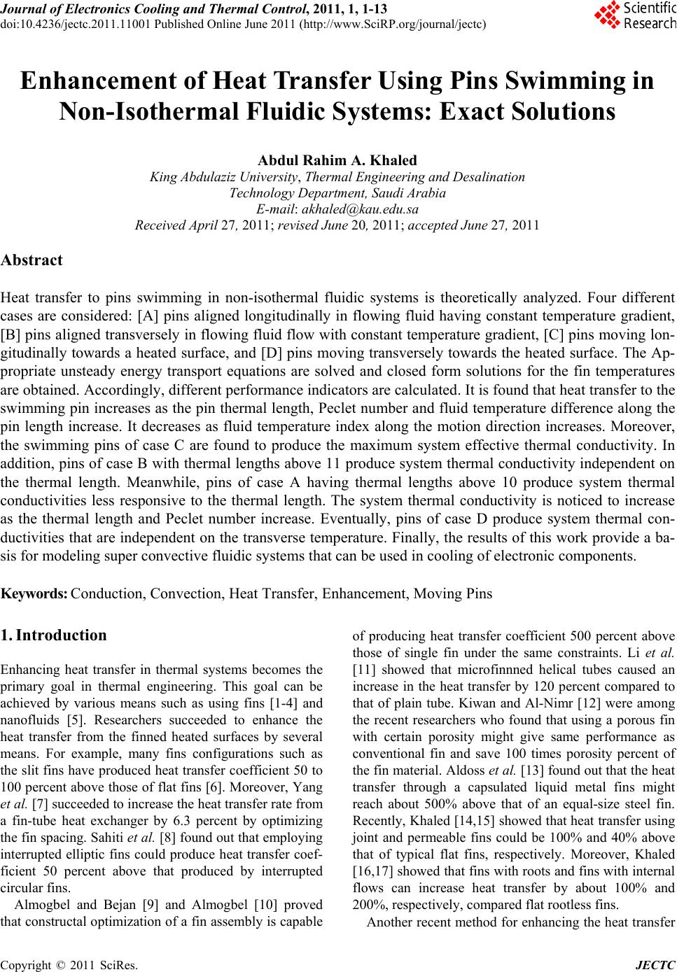
 Journal of Electronics Cooling and Thermal Control, 2011, 1, 1-13 doi:10.4236/jectc.2011.11001 Published Online June 2011 (http://www.SciRP.org/journal/jectc) Copyright © 2011 SciRes. JECTC Enhancement of Heat Transfer Using Pins Swimming in Non-Isothermal Fluidic Systems: Exact Solutions Abdul Rahim A. Khaled King Abdulaziz University, Thermal Engineering and Desalination Technology Department, Saudi Arabia E-mail: akhaled@kau.edu.sa Received April 27, 2011; revised June 20, 2011; accepted June 27, 2011 Abstract Heat transfer to pins swimming in non-isothermal fluidic systems is theoretically analyzed. Four different cases are considered: [A] pins aligned longitudinally in flowing fluid having constant temperature gradient, [B] pins aligned transversely in flowing fluid flow with constant temperature gradient, [C] pins moving lon- gitudinally towards a heated surface, and [D] pins moving transversely towards the heated surface. The Ap- propriate unsteady energy transport equations are solved and closed form solutions for the fin temperatures are obtained. Accordingly, different performance indicators are calculated. It is found that heat transfer to the swimming pin increases as the pin thermal length, Peclet number and fluid temperature difference along the pin length increase. It decreases as fluid temperature index along the motion direction increases. Moreover, the swimming pins of case C are found to produce the maximum system effective thermal conductivity. In addition, pins of case B with thermal lengths above 11 produce system thermal conductivity independent on the thermal length. Meanwhile, pins of case A having thermal lengths above 10 produce system thermal conductivities less responsive to the thermal length. The system thermal conductivity is noticed to increase as the thermal length and Peclet number increase. Eventually, pins of case D produce system thermal con- ductivities that are independent on the transverse temperature. Finally, the results of this work provide a ba- sis for modeling super convective fluidic systems that can be used in cooling of electronic components. Keywords: Conduction, Convection, Heat Transfer, Enhancement, Moving Pins 1. Introduction Enhancing heat transfer in thermal systems becomes the primary goal in thermal engineering. This goal can be achieved by various means such as using fins [1-4] and nanofluids [5]. Researchers succeeded to enhance the heat transfer from the finned heated surfaces by several means. For example, many fins configurations such as the slit fins have produced heat transfer coefficient 50 to 100 percent above those of flat fins [6]. Moreover, Yang et al. [7] succeeded to increase the heat transfer rate from a fin-tube heat exchanger by 6.3 percent by optimizing the fin spacing. Sahiti et al. [8] found out that employing interrupted elliptic fins could produce heat transfer coef- ficient 50 percent above that produced by interrupted circular fins. Almogbel and Bejan [9] and Almogbel [10] proved that constructal optimization of a fin assembly is capable of producing heat transfer coefficient 500 percent above those of single fin under the same constraints. Li et al. [11] showed that microfinnned helical tubes caused an increase in the heat transfer by 120 percent compared to that of plain tube. Kiwan and Al-Nimr [12] were among the recent researchers who found that using a porous fin with certain porosity might give same performance as conventional fin and save 100 times porosity percent of the fin material. Aldoss et al. [13] found out that the heat transfer through a capsulated liquid metal fins might reach about 500% above that of an equal-size steel fin. Recently, Khaled [14,15] showed that heat transfer using joint and permeable fins could be 100% and 40% above that of typical flat fins, respectively. Moreover, Khaled [16,17] showed that fins with roots and fins with internal flows can increase heat transfer by about 100% and 200%, respectively, compared flat rootless fins. Another recent method for enhancing the heat transfer  2 A. -R. A. KHALED from the heated surfaces is by using nanofluids. These are fluids containing suspensions of nanoparticles made of high thermally conductive materials. Nanofluids are noticed to possess large effective thermal conductivities for very low concentrations of nanoparticles. For exam- ple, the effective thermal conductivity of ethylene glycol is increased by about 40% above that of the base fluid when a 0.3% volume of copper nanoparticles of diame- ters less than 10 nm are suspended in the fluid [18]. In addition, Xuan and Li [19] showed that the convective heat transfer coefficient was increased by 60% for nan- ofluid composed of water and 2% Cu-nanoparticles by volume. Finally, the estimated maximum levels of the heat transfer enhancement due to different recent en- hancing methods are summarized in the work of Man- soor et al. [20]. Among these methods are utilizing (a) fins and microfins, (b) porous media, (c) large particles suspensions, (d) nanofluids, (e) phase-change devices, (f) flexible seals, (g) flexible complex seals, (h) vortex gen- erators, (i) protrusions, and (j) ultra high thermal conduc- tivity composite materials. From the previous brief literature survey, it is noticed that many novel ideas were developed recently to en- hance the heat transfer from the solid surfaces. In addi- tion, it is proposed in the present work to consider high thermally conductive pins submerged and swimming in the fluid as a new novel method for enhancing the heat transfer from the solid surface. The pin velocities are considered different from the fluid velocity. It is referred to these pins as to “swimming pins”. The resulting sol- id-fluid system is different from the two-phase flow or the nanofluid system [20] by having the pins moving at constant or predetermined velocity. The velocity of the swimming pins can be attained using different methods. Among these methods are: 1) Applying appropriate magnetic forces on the swimming pins along with using magnetized pins, 2) Applying appropriate centrifugal forces on the fluid/suspended-pins system, and 3) Ap- pling appropriate electrostatic forces on the swimming pins along with using electrically charged pins. To the best author knowledge, this proposal has not been dis- cussed before and it is though to be useful for cooling of electronic components. In this work, four different types of swimming pins are theoretically analyzed. These are the following: [A] Pins swimming longitudinally in flowing fluid having con- stant temperature gradient, [B] Pins aligned transversely and swimming in flowing fluid having constant tem- perature gradient, [C] Pins swimming longitudinally to- wards a heated surface, and [D] Pins moving transversely towards the heated surface. Such these cases can form a basis for constructing and modeling super convective fluid/swimming-pins systems. Appropriate unsteady en- ergy transport equations are identified and solved theo- retically. Closed form solutions for the pin temperature are obtained for each case. Accordingly, different pin performance indicators and the effective thermal conduc- tivity of the fluid/swimming-pins system are computed for the studied cases. 2. Problem Formulation 2.1. Pins Swimming Longitudinally in Flowing Fluid Having Constant Temperature Gradient (Cases A) Consider a pin having a uniform cross-sectional area AC and a uniform perimeter P. This pin is suspended in flowing fluid inside a heated pipe of diameter 2ro. Moreover, the pin is considered to move inside the flow- ing fluid at a constant velocity U. The pin length L which is much larger than its characteristic transverse dimen- sion LC = AC/P is taken for this case to be aligned along the x'-direction as shown in Figure 1. Both x' and U have the same direction. Let the pipe be subjected to constant heat flux q and the mass flow rate of the flowing fluid be . As such, the surrounding fluid stream tempera- ture d inside the pipe can be shown to be equal to the following under fully developed condition: m T , so ddi p qP TxTx x mc (1) where Po, cp, ,di, x' and x are the pipe perimeter T 2π o Pro , fluid specific heat, surrounding fluid stream temperature at the inlet, distance between the inlet and the pin left end and the pin coordinate starting from its left end, respectively. The magnitude of x' is given by x' = Ut where t is the time variable. The one-dimensional energy equation applied to the pin can be written in the following form: 2 2 fffff f fd ffC f TcUT c hP TT kxkA k x T t (2) where Tf, f, cf, kf and h are the pin temperature, pin den- sity, pin specific heat, pin thermal conductivity and the convection heat transfer between the pin and the sur- rounding fluid, respectively. Correlations for the h-coefficient for each case with sufficient accuracy can be obtained using any recent heat transfer textbooks [21]. Applying the following dimensionless variables: *; xL (3a) *; Ut tL (3b) Copyright © 2011 SciRes. JECTC  A. -R. A. KHALED Copyright © 2011 SciRes. JECTC 3 Figure 1. Schematic diagram for swimming pins of cases: A and B, and the flow configurations with coordinates system. , d di d TT TT (3c) on Equation (2) will change it to the following dimen- sionless form: 22 11 *2 * 1* 22 2 ff ff PemL Pe xx PePe t (4) where Pe (pin Peclet number), m (pin index) and 1 (characteristic function) are given by ; ff ff cUL Pe k (5a) ; C hP mkA (5b) 1** 1 t (5c) The pin is considered to be insulated from both left and right ends. In addition, it is considered to be at tem- perature , di when t = 0. As such, the dimen- sionless boundaries and initial conditions are given by TT ** ** * 0, 0, 1; xt tx x * t (6a) ** ** * 1, 1 xt tx x * 1,1;t 1 (6b) ** ,0xt (6c) The net heat transfer rate from the pin to the flowing fluid, d q , is given by 1 * 0 1 ** * 0 d d fd d so p qhPLTTx qPL hPLx tx mc (7) The temperature increase across any pipe differential element of thickness L which is denoted by TL is equal to so p TqPLmc . Define the dimensionless pin heat transfer rate A as the ratio between the pin heat transfer rate to that having maximum temperature difference of TL. Mathematically, it is equal to 1 ** * 0 d fd AL q tx hPL T (8) Closed Form Solutions Define the variable ** , xt as the following: *** *** ,, xtx txt (9) Substituting Equation (9) in Equation (4) results in the following form of energy equation: 22 *2 ** 2 fff gg PemL gPePe xt (10) The boundaries and initial conditions are obtained by substituting Equation (9) in Equations (6a-c). As such, the boundary and initial conditions of ** , xt are giv- en by ** ** 01 ** * 1; ,0 xx gg xx gxt x (11a-c)  4 A. -R. A. KHALED The solution of ** , xt can be decomposed into sum of two solutions: 1) the steady state solution * sA x and, 2) the homogenous solution ** , A t . The corresponding governing equations for each one are taken to be 22 *2 * dd 2 dd sA sA fsA gg PemL gPe xx 0 f (12) 22 *2 ** AA fA PemLPe A f xt (13) The corresponding boundary and initial conditions are taken to be ** ** 01 dd 1; dd sA sA xx gg xx (14a) ** ** ** 0, 1, 0; AA xt xt xx sA (14b) *** * ,0 A txg x * 1 (14c) Utilizing the theory of ordinary differential equations, separation of variables and the Sturm-Liouville theory [17], the following solutions can be obtained: ** 112 2 exp exp sA xC sxCsx A (15) 2 ** * 2 * *22* * 1 ,exp exp 4 exp π 2 Aa f f f f nn nf mL xt Et Pe Pe mL t Pe Pe xnt EX Pe nx (16) where A1, C1, C2, s1 and s2 are equal to 12 2; f Pe AmL (17a) 2 1 12 1 exp1 ; exp exp s Css s (17b) 1 2 22 1 1exp ; exp exp s Css s (17c) 2 2 1; 24 ff Pe Pe mL (17d) 2 2 224 ff Pe Pe mL (17e) The functions * π n nx are equal to ** πcos πsin π 2π f n Pe * nx nxnx n (18) The constants Ea and En’s are equal to 1 2 1 11 exp 1 exp exp exp 1 aff fm mf mmf f EA Pe Pe Pes CPe Pe Pe (19a) 2 2 22 22 22 2 2 2 122 22 exp1 1 2 1π 4 2π 2πexp1 1 2 ππ 42 n f n f n f mm m mff m Pe EPe n n Pe nCs s Pe Pe ns n (19b) As such, the dimensionless heat transfer rate is equal to 12 11 2 12 2 * 2 * 22* 2 122 1exp 1exp exp exp 4 exp1 1 2 π exp π 4 A af f f f n f n nff CC As s ss mL EtPe Pe Pe mL t Pe Pe nt EPe Pe n (20) The maximum effective swimming pin index denoted by m can be obtained by solving the following equation: 0.99 fd fd mm m qq . As such, mL for this case is obtained by solving the following equation: 2 ** sinh2 cosh0.01sinh f* Pesm Ls (21) where 2 *4 f smLPe 2 . Note that the maximum heat transfer rate is equal to Copyright © 2011 SciRes. JECTC  A. -R. A. KHALED 5 22 dfCLfffC m qkATPeLcA L UT . 2.2. Pins Aligned Transversely and Swimming in Flowing Fluid Having Constant Temperature Gradient (Cases B) Let the pin described in section 2.1 be aligned trans- versely such that the pin centerline is normal to the U-direction as shown in Figure 1. The fluid temperature around the pin can be approximated by the following expression: so did p qP x Tx TTUt Lmc (22) where d is the fluid undisturbed stream temperature increase across the pin length. Define the dimensionless time according to the following: T * 2 f ff kt tcL (23) According to Equation (23) and Equation (3a), Equa- tion (22) changes to *** * , didL Txt T TxTPet f (24) The one-dimensional energy equation applied to the pin for this case has the following form: 2 2 ff f fd fC f T hP TT kAk t x cT (25) Utilizing the dimensionless variables given by Equa- tion (3a,c) and Equation (23), Equation (25) can be changed to the following dimensionless form: 22 212 *2 ** 2mL xt (26) where 2 (characteristic function) and 1 (Tempera- ture difference ratio) are given by 2** 1 1; t (27a) 1 L d TPe T (27b) The dimensionless boundaries and initial conditions as adopted in section 2.1 can be expressed in the following dimensionless forms: ** ** 1* 0, 0, 1; xt tx x ** ** 1* 1, 1 xt tx x * 1,1;t (28b) ** ,0xt 1 * (28c) The heat transfer from the pin to the flowing fluid is given by 1 * 0 1 ** 1 0 d d fd d d qhPLTTx hPL Txtx (29) Define the dimensionless pin heat transfer rate B as the ratio between the pin heat transfer rate to that having maximum temperature difference of . Mathemati- cally, it is equal to d T 1 ** 1 0 d fd Bd q* tx hPL T (30) Closed Form Solutions Redefine the variable ** , xt as the following: ** ** 1 ,, * * xtx t xt (31) Substituting Equation (31) in Equation (25) results in the following dimensionless form of the energy equation: 22 *2 * f g mL gPe t (32) The boundaries and initial conditions are obtained by substituting Equation (31) in Equations (28a-c). They are given by Equations (11a-c). The equations for the steady state and homogenous solutions are given by 22 *2 d0 d sB sB gmL g x (33) 22 *2 * B B mL t (34) The corresponding boundary and initial conditions are given by Equations (14a-c). Utilizing the theory of ordi- nary differential equations, separation of variables and the Sturm-Liouville theory [22], the following solutions can be obtained. ** *coshcosh 1 sinh sB mLxmLx gx mL mL (35) 2 ***22* * 1 ,exp expπcos π Bn n tmLtFntn x (36) The coefficients Fn are equal to 222 22 11 11 2ππ nn n FnmL n (37) * t (28a) Copyright © 2011 SciRes. JECTC  6 A. -R. A. KHALED As such, the dimensionless heat transfer rate is equal to 2*22* 22 1 11 expexp π π n Bn n mL tFntn (38) The steady state value of is zero. According to Equation (35), the pin base section is located at where the convection heat transfer changes its direction at this section. Therefore, the maximum conduction heat transfer rate through this pin is obtained from the fol- lowing mathematical relationship: *0.5x * * 0.5 11 cosh 2 f C ff x C fd T A qk Lx A kT LmL (39) As such, the pin maximum dimensionless conduction heat transfer denoted by is equal to 2 11 1cosh 2 f d q hPL TmL mL (40) The effective swimming pin length denoted by L can be obtained by solving the following equation: 0.99 f LL L qq f . As such, mL can be shown to be . 10.597mL 2.3. Pins Swimming Longitudinally Towards a Heated Surface (Cases C) Let the pin described in section 2.1 be moving towards a hot surface with temperature Ts at a constant velocity U as shown in Figure 2. The fluid stream temperature sur- rounding the pin can be approximated by the following expression: exp ds TxTT Tbx x (41) where T , b, x' and x are the fluid far stream temperature, positive quantity, the position vector of the pin upper end and the pin axial coordinate starting from the pin upper end, respectively. The position vector x' is a time de- pendent quantity given by x' = xo – Ut where t is the time variable. In terms of dimensionless variables given by Equation (3a,b), Equation (41) changes to *** * ,exp ds TxtTT TCBxt x (42) where B and C are equal to ;BbL (43a) exp o Cb (43b) According to Equation (41), the dimensionless time Figure 2. Schematic diagram for swimming pins of cases: C and D, and the flow configurations with coordinates system. required for the pin to reach the heated surface is equal to *1 fo txL . Redefining Equation (3c) as ** ** ** ** ,, ,, d d TxtT xt xt TTxt (44) Applying the dimensionless variables given by Equa- tion (3a,b) and Equation (44) on Equation (2) will change it to the following dimensionless form: 2222 *2 * * 22 2 ff ff PeBmLPe BBB xx BPePe t (45) The dimensionless boundaries and initial conditions as adopted in section 2.1 can be expressed in the following dimensionless forms: ** ** * 0, 0, ; xt BxtB x (46a) ** ** * 1, 1, ; xt BxtB x (46b) ** ,0xt 1 (46c) The heat transfer from the pin to the flowing fluid is given by 1 * 0 1 *** 0 d exp d fd d s qhPLTTx hPL TTCBxtx (47) Define the dimensionless pin heat transfer rate C as the ratio between the pin heat transfer rate to that having maximum temperature difference of s TTT . Mathematically, it is equal to Copyright © 2011 SciRes. JECTC 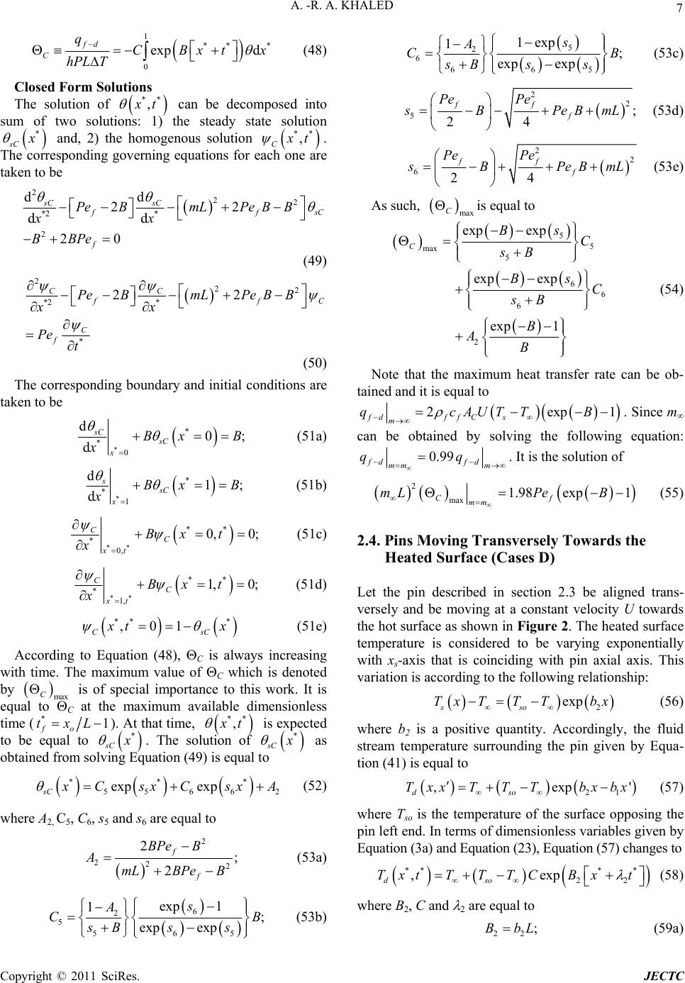 A. -R. A. KHALED 7 1 *** 0 exp d fd C qCBxt hPL T x (48) Closed Form Solutions The solution of ** , t can be decomposed into sum of two solutions: 1) the steady state solution * sC and, 2) the homogenous solution ** , C t . The corresponding governing equations for each one are taken to be 222 *2 * 2 dd 22 dd 20 sC sC f f PeBmLPe BB xx BBPe sC (49) 222 *2 * * 22 CC fC C f PeBmLPe BB xx Pe t (50) The corresponding boundary and initial conditions are taken to be * * * 0 d0 d sC sC x Bx B x ; (51a) * * * 1 d1 d ssC x Bx B x ; (51b) ** ** * 0, 0, 0; CC xt Bx t x (51c) ** ** * 1, 1, 0; CC xt Bx t x sC (51d) ** * ,01 C t x (51e) According to Equation (48), C is always increasing with time. The maximum value of C which is denoted by max C is of special importance to this work. It is equal to C at the maximum available dimensionless time ( * fo tx1L ). At that time, ** , t is expected to be equal to * sC . The solution of * sC as obtained from solving Equation (49) is equal to ** 55 66 exp exp sC * 2 CsxCsx A (52) where A2, C5, C6, s5 and s6 are equal to 2 222 2; 2 f f BPe B AmLBPe B (53a) 6 2 5 565 exp 1 1; exp exp s A CB sB ss (53b) 5 2 6 665 1exp 1; exp exp s A CB sB ss (53c) 2 2 5; 24 ff f Pe Pe BPeBm L (53d) 2 2 624 ff f Pe Pe BPeB mL (53e) As such, max C is equal to 5 5 max 5 6 6 6 2 exp exp exp exp exp 1 C Bs C sB Bs C sB B AB (54) Note that the maximum heat transfer rate can be ob- tained and it is equal to 2exp fdf fCs m qcAUTT 1B . Since m can be obtained by solving the following equation: 0.99 fd fd mm m qq . It is the solution of 2 max 1.98 exp1 Cf mm mLPe B (55) 2.4. Pins Moving Transversely Towards the Heated Surface (Cases D) Let the pin described in section 2.3 be aligned trans- versely and be moving at a constant velocity U towards the hot surface as shown in Figure 2. The heated surface temperature is considered to be varying exponentially with xs-axis that is coinciding with pin axial axis. This variation is according to the following relationship: 2 exp sso Tx TTTbx (56) where b2 is a positive quantity. Accordingly, the fluid stream temperature surrounding the pin given by Equa- tion (41) is equal to 21 ,exp dso TxxTT Tbxbx ' (57) where Tso is the temperature of the surface opposing the pin left end. In terms of dimensionless variables given by Equation (3a) and Equation (23), Equation (57) changes to *** * 22 ,exp dso TxtTT TCBxt (58) where B2, C and 2 are equal to 22 ;BbL (59a) Copyright © 2011 SciRes. JECTC  8 A. -R. A. KHALED 1 exp ; o Cbx (59b) 11 ;BbL (59c) 21f BPeB 2 (59d) According to Equation (57), the dimensionless time required for the pin to reach the heated boundary is given by * of . Applying the dimensionless vari- ables given by Equation (3a), Equation (44) and Equa- tion (23) on Equation (25) will change it to the following dimensionless form: txLPe 222 221 *2 * 1* 2f f BmLBBPe xx BPet 2 2 B (60) The dimensionless boundaries and initial conditions as adopted in section 2.1 can be expressed in the following dimensionless forms: ** ** ** 22 * 0, ** ** 22 * 1, 0, ; 1,;,0 1 xt xt Bxt B x BxtB xt x * (61) The heat transfer from the pin to the flowing fluid is given by 1 * 0 1 ** 22 0 d exp d fd d so qhPLTTx hPL TTCBxtx (62) Define the dimensionless pin heat transfer rate D as the ratio between the pin heat transfer rate to that with maximum temperature difference of Dso TTT . Mathematically, it is equal to 1 ** 22 0 exp d f DD qCBxt hPL T * x (63) Closed Form Solutions According to Equation (62), D is always increasing with time. As such, the maximum value of D, denoted by , is computed at dimensionless time given by max D * fo txL. At that time, ** , t is expected to be equal to sD * . The solution of * sD as obtained from solving Equation (60) at large times is equal to ** 77 88 exp exp sD * 3 CsxCsx A (64) where A3, C7, C8, s7 and s8 are equal to 2 12 322 12 ; f f BPe B AmLBPeB (65a) 8 3 72 7287 exp 1 1; exp exp s A CB sBs s (65b) 7 3 82 828 7 1exp 1; exp exp s A CB sBs s (65c) 2 72 1 ; BmLBPe (65d) 2 82 1 ; BmLBPe (65e) As such, max D is equal to 72 82 78 max 72 82 2 3 2 1exp 1exp 1exp D sB sB CC sB sB BA B (66) Equation (66) is reducible to the following expression: 12 2 max 2 1 exp 1 f D f BPeB B mLBPe (67) The maximum effective swimming pin index denoted by m can be obtained by solving the following equation: 0.99 fd fd mmm qq . As such, the dimensionless effective length for this case mL can be obtained to be equal to 1 9.95 mL BPe . 2.5. Effective Thermal Conductivity for the Fluid Loaded With Swimming Pins of Kind (A) Suppose that the pin volume fraction is equal to fsf nV V where nf is the number of swimming pins, Vsf is the volume of a single pin and V is the fluid volume. The maximum value of is taken to be 1.5% which is expected to cause insignificant effect on the fluid flow pressure drop [5,19]. The net heat flux received by the fluid can be shown to be equal to o fd Co d ds Co rr q AT qq k APL r (68) where ACo, k and r are the pipe cross-sectional area 2 π Co r, fluid thermal conductivity and the pipe ra- dial coordinate, respectively. For homogenous mixture of the swimming pins and the pure fluid, the mixture can be approximated as a continuum fluid with effective thermal conductivity keffA. For this case, the boundary heat flux, q , is given by Copyright © 2011 SciRes. JECTC 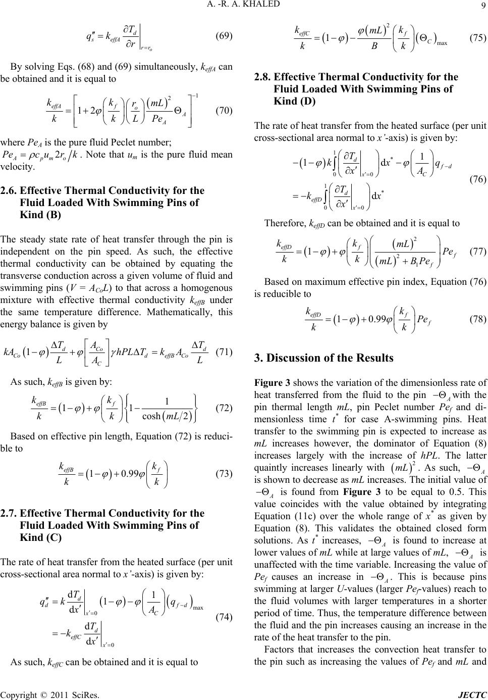 A. -R. A. KHALED 9 o d s effA rr T qk r (69) By solving Eqs. (68) and (69) simultaneously, keffA can be obtained and it is equal to 1 2 12 effAf oA A kk mL r kkLPe (70) where PeA is the pure fluid Peclet number; 2 Apmo Pec urk . Note that um is the pure fluid mean velocity. 2.6. Effective Thermal Conductivity for the Fluid Loaded With Swimming Pins of Kind (B) The steady state rate of heat transfer through the pin is independent on the pin speed. As such, the effective thermal conductivity can be obtained by equating the transverse conduction across a given volume of fluid and swimming pins (V = ACoL) to that across a homogenous mixture with effective thermal conductivity keffB under the same temperature difference. Mathematically, this energy balance is given by 1dCo CodeffB Co C TA kAhPL TkA LA d T L (71) As such, keffB is given by: 1 11 cosh 2 effB f kk kk mL (72) Based on effective pin length, Equation (72) is reduci- ble to 10.99 effB f kk kk (73) 2.7. Effective Thermal Conductivity for the Fluid Loaded With Swimming Pins of Kind (C) The rate of heat transfer from the heated surface (per unit cross-sectional area normal to x’-axis) is given by: max 0 0 d1 1 d d d d d C x d effC x T qk q xA T kx f d (74) As such, keffC can be obtained and it is equal to 2 max 1 effCf C kk mL kBk (75) 2.8. Effective Thermal Conductivity for the Fluid Loaded With Swimming Pins of Kind (D) The rate of heat transfer from the heated surface (per unit cross-sectional area normal to x’-axis) is given by: 1 * 00 1 * 00 1 1d d d d C x d effD x T kx xA T kx x q (76) Therefore, keffD can be obtained and it is equal to 2 2 1 1 effD f f kk mL Pe kk mLBPe (77) Based on maximum effective pin index, Equation (76) is reducible to 10.99 effD f kk Pe kk (78) 3. Discussion of the Results Figure 3 shows the variation of the dimensionless rate of heat transferred from the fluid to the pin Awith the pin thermal length mL, pin Peclet number Pef and di- mensionless time t* for case A-swimming pins. Heat transfer to the swimming pin is expected to increase as mL increases however, the dominator of Equation (8) increases largely with the increase of hPL. The latter quaintly increases linearly with . As such, A 2 mL is shown to decrease as mL increases. The initial value of A is found from Figure 3 to be equal to 0.5. This value coincides with the value obtained by integrating Equation (11c) over the whole range of x* as given by Equation (8). This validates the obtained closed form solutions. As t* increases, A is found to increase at lower values of mL while at large values of mL, A is unaffected with the time variable. Increasing the value of Pef causes an increase in A . This is because pins swimming at larger U-values (larger Pef-values) reach to the fluid volumes with larger temperatures in a shorter period of time. Thus, the temperature difference between the fluid and the pin increases causing an increase in the rate of the heat transfer to the pin. Factors that increases the convection heat transfer to the pin such as increasing the values of Pef and mL and Copyright © 2011 SciRes. JECTC 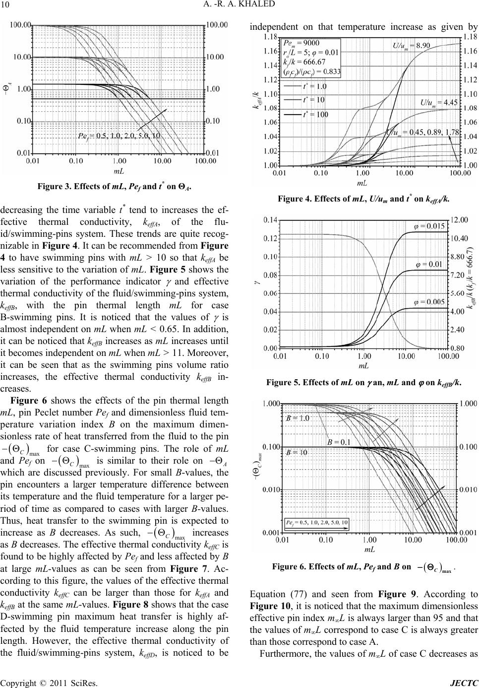 10 A. -R. A. KHALED Figure 3. Effects of mL, Pef and t* on ΘA. decreasing the time variable t* tend to increases the ef- fective thermal conductivity, keffA, of the flu- id/swimming-pins system. These trends are quite recog- nizable in Figure 4. It can be recommended from Figure 4 to have swimming pins with mL > 10 so that keffA be less sensitive to the variation of mL. Figure 5 shows the variation of the performance indicator and effective thermal conductivity of the fluid/swimming-pins system, keffB, with the pin thermal length mL for case B-swimming pins. It is noticed that the values of is almost independent on mL when mL < 0.65. In addition, it can be noticed that keffB increases as mL increases until it becomes independent on mL when mL > 11. Moreover, it can be seen that as the swimming pins volume ratio increases, the effective thermal conductivity keffB in- creases. Figure 6 shows the effects of the pin thermal length mL, pin Peclet number Pef and dimensionless fluid tem- perature variation index B on the maximum dimen- sionless rate of heat transferred from the fluid to the pin for case C-swimming pins. The role of mL and Pef on max C is similar to their role on A max C which are discussed previously. For small B-values, the pin encounters a larger temperature difference between its temperature and the fluid temperature for a larger pe- riod of time as compared to cases with larger B-values. Thus, heat transfer to the swimming pin is expected to increase as B decreases. As such, max C increases as B decreases. The effective thermal conductivity keffC is found to be highly affected by Pef and less affected by B at large mL-values as can be seen from Figure 7. Ac- cording to this figure, the values of the effective thermal conductivity keffC can be larger than those for keffA and keffB at the same mL-values. Figure 8 shows that the case D-swimming pin maximum heat transfer is highly af- fected by the fluid temperature increase along the pin length. However, the effective thermal conductivity of the fluid/swimming-pins system, keffD, is noticed to be independent on that temperature increase as given by Figure 4. Effects of mL, U/um and t* on keffA/k. Figure 5. Effects of mL on an, mL and on keffB/k. Figure 6. Effects of mL, Pef and B on . max C Equation (77) and seen from Figure 9. According to Figure 10, it is noticed that the maximum dimensionless effective pin index mL is always larger than 95 and that the values of mL correspond to case C is always greater than those correspond to case A. Furthermore, the values of mL of case C decreases as Copyright © 2011 SciRes. JECTC 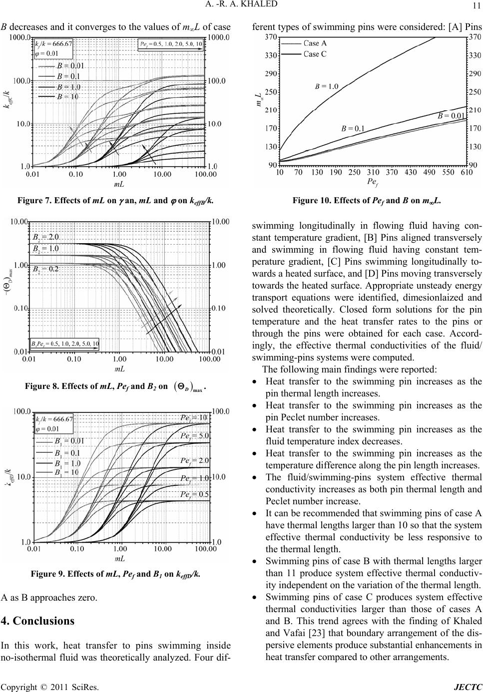 A. -R. A. KHALED 11 B decreases and it converges to the values of mL of case Figure 7. Effects of mL on an, mL and on keffB/k. Figure 8. Effects of mL, Pef and B2 on . max D Figure 9. Effects of mL, Pef and B1 on keffD/k. A as B approaches zero. 4. Conclusions In this work, heat transfer to pins swimming inside no-isothermal fluid was theoretically analyzed. Four dif- ferent types of swimming pins were considered: [A] Pins Figure 10. Effects of Pef and B on mL. swimming longitudinally in flowing fluid having con- stant temperature gradient, [B] Pins aligned transversely and swimming in flowing fluid having constant tem- perature gradient, [C] Pins swimming longitudinally to- wards a heated surface, and [D] Pins moving transversely towards the heated surface. Appropriate unsteady energy transport equations were identified, dimesionlaized and solved theoretically. Closed form solutions for the pin temperature and the heat transfer rates to the pins or through the pins were obtained for each case. Accord- ingly, the effective thermal conductivities of the fluid/ swimming-pins systems were computed. The following main findings were reported: Heat transfer to the swimming pin increases as the pin thermal length increases. Heat transfer to the swimming pin increases as the pin Peclet number increases. Heat transfer to the swimming pin increases as the fluid temperature index decreases. Heat transfer to the swimming pin increases as the temperature difference along the pin length increases. The fluid/swimming-pins system effective thermal conductivity increases as both pin thermal length and Peclet number increase. It can be recommended that swimming pins of case A have thermal lengths larger than 10 so that the system effective thermal conductivity be less responsive to the thermal length. Swimming pins of case B with thermal lengths larger than 11 produce system effective thermal conductiv- ity independent on the variation of the thermal length. Swimming pins of case C produces system effective thermal conductivities larger than those of cases A and B. This trend agrees with the finding of Khaled and Vafai [23] that boundary arrangement of the dis- persive elements produce substantial enhancements in heat transfer compared to other arrangements. Copyright © 2011 SciRes. JECTC 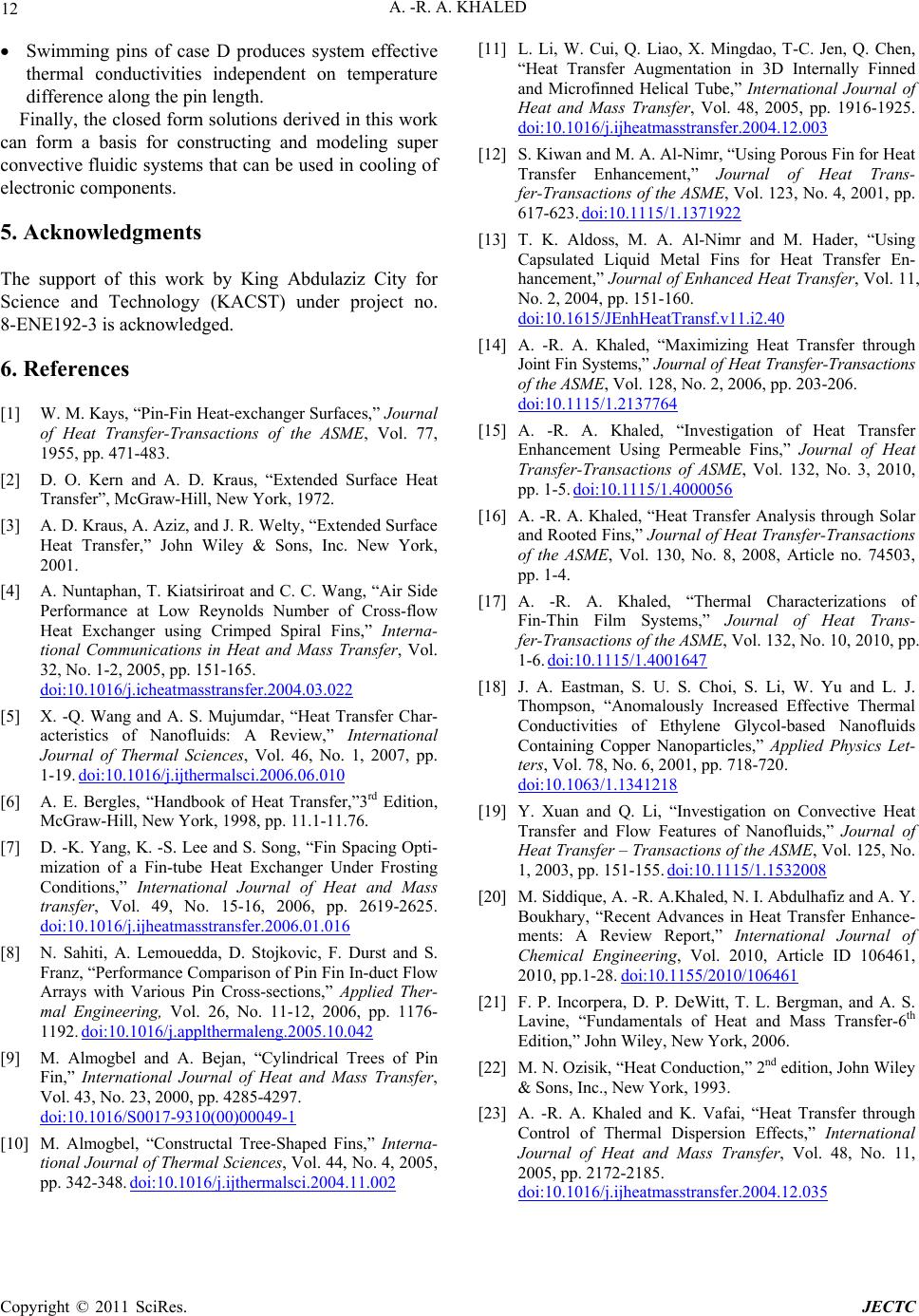 A. -R. A. KHALED Copyright © 2011 SciRes. JECTC 12 Swimming pins of case D produces system effective thermal conductivities independent on temperature difference along the pin length. Finally, the closed form solutions derived in this work can form a basis for constructing and modeling super convective fluidic systems that can be used in cooling of electronic components. 5. Acknowledgments The support of this work by King Abdulaziz City for Science and Technology (KACST) under project no. 8-ENE192-3 is acknowledged. 6. References [1] W. M. Kays, “Pin-Fin Heat-exchanger Surfaces,” Journal of Heat Transfer-Transactions of the ASME, Vol. 77, 1955, pp. 471-483. [2] D. O. Kern and A. D. Kraus, “Extended Surface Heat Transfer”, McGraw-Hill, New York, 1972. [3] A. D. Kraus, A. Aziz, and J. R. Welty, “Extended Surface Heat Transfer,” John Wiley & Sons, Inc. New York, 2001. [4] A. Nuntaphan, T. Kiatsiriroat and C. C. Wang, “Air Side Performance at Low Reynolds Number of Cross-flow Heat Exchanger using Crimped Spiral Fins,” Interna- tional Communications in Heat and Mass Transfer, Vol. 32, No. 1-2, 2005, pp. 151-165. doi:10.1016/j.icheatmasstransfer.2004.03.022 [5] X. -Q. Wang and A. S. Mujumdar, “Heat Transfer Char- acteristics of Nanofluids: A Review,” International Journal of Thermal Sciences, Vol. 46, No. 1, 2007, pp. 1-19. doi:10.1016/j.ijthermalsci.2006.06.010 [6] A. E. Bergles, “Handbook of Heat Transfer,”3rd Edition, McGraw-Hill, New York, 1998, pp. 11.1-11.76. [7] D. -K. Yang, K. -S. Lee and S. Song, “Fin Spacing Opti- mization of a Fin-tube Heat Exchanger Under Frosting Conditions,” International Journal of Heat and Mass transfer, Vol. 49, No. 15-16, 2006, pp. 2619-2625. doi:10.1016/j.ijheatmasstransfer.2006.01.016 [8] N. Sahiti, A. Lemouedda, D. Stojkovic, F. Durst and S. Franz, “Performance Comparison of Pin Fin In-duct Flow Arrays with Various Pin Cross-sections,” Applied Ther- mal Engineering, Vol. 26, No. 11-12, 2006, pp. 1176- 1192. doi:10.1016/j.applthermaleng.2005.10.042 [9] M. Almogbel and A. Bejan, “Cylindrical Trees of Pin Fin,” International Journal of Heat and Mass Transfer, Vol. 43, No. 23, 2000, pp. 4285-4297. doi:10.1016/S0017-9310(00)00049-1 [10] M. Almogbel, “Constructal Tree-Shaped Fins,” Interna- tional Journal of Thermal Sciences, Vol. 44, No. 4, 2005, pp. 342-348. doi:10.1016/j.ijthermalsci.2004.11.002 [11] L. Li, W. Cui, Q. Liao, X. Mingdao, T-C. Jen, Q. Chen, “Heat Transfer Augmentation in 3D Internally Finned and Microfinned Helical Tube,” International Journal of Heat and Mass Transfer, Vol. 48, 2005, pp. 1916-1925. doi:10.1016/j.ijheatmasstransfer.2004.12.003 [12] S. Kiwan and M. A. Al-Nimr, “Using Porous Fin for Heat Transfer Enhancement,” Journal of Heat Trans- fer-Transactions of the ASME, Vol. 123, No. 4, 2001, pp. 617-623. doi:10.1115/1.1371922 [13] T. K. Aldoss, M. A. Al-Nimr and M. Hader, “Using Capsulated Liquid Metal Fins for Heat Transfer En- hancement,” Journal of Enhanced Heat Transfer, Vol. 11, No. 2, 2004, pp. 151-160. doi:10.1615/JEnhHeatTransf.v11.i2.40 [14] A. -R. A. Khaled, “Maximizing Heat Transfer through Joint Fin Systems,” Journal of Heat Transfe r-Transactions of the ASME, Vol. 128, No. 2, 2006, pp. 203-206. doi:10.1115/1.2137764 [15] A. -R. A. Khaled, “Investigation of Heat Transfer Enhancement Using Permeable Fins,” Journal of Heat Transfer-Transactions of ASME, Vol. 132, No. 3, 2010, pp. 1-5. doi:10.1115/1.4000056 [16] A. -R. A. Khaled, “Heat Transfer Analysis through Solar and Rooted Fins,” Journal of Heat Transfer-Transactions of the ASME, Vol. 130, No. 8, 2008, Article no. 74503, pp. 1-4. [17] A. -R. A. Khaled, “Thermal Characterizations of Fin-Thin Film Systems,” Journal of Heat Trans- fer-Transactions of the ASME, Vol. 132, No. 10, 2010, pp. 1-6. doi:10.1115/1.4001647 [18] J. A. Eastman, S. U. S. Choi, S. Li, W. Yu and L. J. Thompson, “Anomalously Increased Effective Thermal Conductivities of Ethylene Glycol-based Nanofluids Containing Copper Nanoparticles,” Applied Physics Let- ters, Vol. 78, No. 6, 2001, pp. 718-720. doi:10.1063/1.1341218 [19] Y. Xuan and Q. Li, “Investigation on Convective Heat Transfer and Flow Features of Nanofluids,” Journal of Heat Transfer – Transactions of the ASME, Vol. 125, No. 1, 2003, pp. 151-155. doi:10.1115/1.1532008 [20] M. Siddique, A. -R. A.Khaled, N. I. Abdulhafiz and A. Y. Boukhary, “Recent Advances in Heat Transfer Enhance- ments: A Review Report,” International Journal of Chemical Engineering, Vol. 2010, Article ID 106461, 2010, pp.1-28. doi:10.1155/2010/106461 [21] F. P. Incorpera, D. P. DeWitt, T. L. Bergman, and A. S. Lavine, “Fundamentals of Heat and Mass Transfer-6th Edition,” John Wiley, New York, 2006. [22] M. N. Ozisik, “Heat Conduction,” 2nd edition, John Wiley & Sons, Inc., New York, 1993. [23] A. -R. A. Khaled and K. Vafai, “Heat Transfer through Control of Thermal Dispersion Effects,” International Journal of Heat and Mass Transfer, Vol. 48, No. 11, 2005, pp. 2172-2185. doi:10.1016/j.ijheatmasstransfer.2004.12.035  A. -R. A. KHALED 13 Nomenclature A1-A3 steady state particular solutions; Equations (17a), (53a) & (65a) AC pin cross-sectional area ACo pipe cross-sectional area B, B1, B2 exponential functions dimensionless indices b, b1, b2 exponential functions indices C1-C8 steady state general solutions coefficients; Equations (17b, c), (53b, c) & (65b, c) cp pure fluid specific heat [J/kgK] Ea, En homogenous solution coefficients; Equation (19a, b) Fn homogenous solution coefficients; Equation (37) g transformed dimensionless temperature; Equa- tion (9) & Equation (31) gs transformed dimensionless steady state tem- perature; Equation (12) & Equation (35) h convection heat transfer coefficient between the pin and the fluid [W/m2K] k pure fluid thermal conductivity [W/m.K] keff Effective fluid-swimming pins thermal con- ductivity; Equation (70), (72), (75) & (77) kf pin thermal conductivity [W/m.K] L pin length [m] m pin index [m] n Integer (n = 1, 2, 3, , ) nf number of swimming pins PeA Peclet number for case A (PeA = cpum2ro/k) Pef pin Peclet number (Pef = fcfUL/kf) qf-d total convection heat transfer rate from the pin to the fluid [W] qf pin maximum conduction heat transfer rate [W] r radius axis [m] ro inner radius of the pipe [m] s1-s8 steady state general solutions exponential di- mensionless indices; Equations 17(d, e), 53(d, e) & 65(d, e) Td pin surrounding fluid temperature [K] Td,i pin surrounding fluid temperature at the pipe inlet [K] Tf pin temperature [K] Ts heated surface temperature [K] Tso reference heated surface temperature [K] T outer fluid free stream temperature [K] t time variable [s] t* Dimensionless time; Equation (3b) & Equa- tion (23) U swimming pin velocity [m/s] um Mean fluid velocity inside the pipe for cases (A) and (B) [m/s] V Fluid and swimming pins volume per pin length (V = ACoL) Vsf Volume of single pin (Vsf = ACL) x pin axial coordinate [m] x' pin leading edge position vector [m] xo pin leading edge initial position vector [m] x* dimensionless x-coordinate (x*=x/L) Greek symbols dimensionless pin convection heat transfer; Equations (8), (30), (48) & (63) 12 , characteristic functions; Equation (5c) & Equ- ation (27a) pin maximum dimensionless conduction heat transfer for case B; Equation (40) Swimming pins to fluid volume ratio fsf nV V 1, 2 pin to fluid temperature difference ratios times pin Peclet number; Equations (27b) (59d) pin dimensionless temperature; Equation (3c) & Equation (44) inner fluid density [kg/m3] homogenous solution; Equation (16) & Equa- tion (36) Subscripts A, B, C, D cases A, B, C and D s steady state Copyright © 2011 SciRes. JECTC
|