Paper Menu >>
Journal Menu >>
 I. J. Communications, Network and System Sciences, 2008, 2, 105-206 Published Online May 2008 in SciRes (http://www.SRPublishing.org/journal/ijcns/). Copyright © 2008 SciRes. I. J. Communications, Network and System Sciences, 2008, 2, 105-206 A Novel Adaptive Hybrid Error Correction Scheme for Wireless DVB Services Guoping TAN1, Thorsten HERFET2 1 Student Member, IEEE, 2 Senior Member, IEEE FR 6.2 – Telecommunications Lab, Saarland University Campus Building C6 3, Floor 10, 66123 Saarbrücken, Germany E-mail: {tan, herfet}@nt.uni-saarland.de Abstract Real-time applications usually not only have a certain Packet Loss Ratio (PLR) requirement but also can have strict delay constraints. In the past, we proposed a Hybrid Error Correction (HEC) scheme with Packet Repetition (PR) technique for guaranteeing a certain PLR requirement under strict delay constraints. Unfortunately, the HEC-PR scheme can only work efficiently in multicast scenarios with small group size and small link PLR. Our further studies show that better performance can be obtained by combining the HEC-PR scheme with other traditional HEC schemes such as Type I HARQ and Type II HARQ techniques. Based on this idea, in this paper, a novel Adaptive HEC (AHEC) scheme combining the HEC-PR scheme with Type I and Type II HARQ techniques is proposed to satisfy a certain PLR requirement for delay bounded multicast services. Furthermore, the performance of the AHEC scheme is optimized by choosing the scheme with the least needed redundancy information automatically among the three HEC schemes. Finally, by applying the AHEC scheme in a typical wireless DVB scenario, we analyze the performances of the AHEC scheme and compare it with the HEC-PR scheme and an Adaptive Forward Error Correction (AFEC) scheme. The results show that the proposed AHEC scheme outperforms both the AFEC scheme and the HEC-PR scheme. Keywords: ARQ, Forward Error Correction (FEC), Hybrid ARQ (HARQ), Multicast, Wireless Networks 1. Introduction With the rapid development of broadband wireless networks, more and more attention has turned to distributing real time multimedia services over wireless networks. Many classes of mobile commerce applications require or can benefit from real-time multicast support in wireless networks: mobile auction or reverse auction, mobile entertainment services and interactive games, mobile distance educations etc. [1]. As a major example, most of our personal digital assistants (PDAs) and laptops are factory-equipped with a Wi-Fi interface. In recent years, more and more places are covered by wireless LANs with the IEEE 802.11 [2] family of protocols in hotspots like hotels, airports or conference locations. This will allow travelers to use their PDAs or laptops for watching television broadcastings, enjoying games or participating in video conferences etc. All these new real-time multicast applications are very likely to appear soon with upcoming WiMAX or DVB-H [3] enabled devices. In the following, to show the packet loss issue in wireless real-time multicast systems, we will take the practical Digital Video Broadcasting (DVB) services over wireless LANs as the example for illustration. We know that the IEEE 802.11 has been expected to be used for DVB services over home and nomadic networks. Moreover, since IP multicast provides a scalable and efficient means for distributing datagram to a group of receivers [4], IP-based networks were proposed for delivering DVB services [5]. The DVB systems based on IP multicast typically employ an application-level protocol to provide some information about the set of receivers and reception quality statistics. The Real-time Transport Protocol (RTP) [6] is usually used for this purpose. RTP or MAC layer of the IEEE 802.11 does not, however, guarantee any Quality of 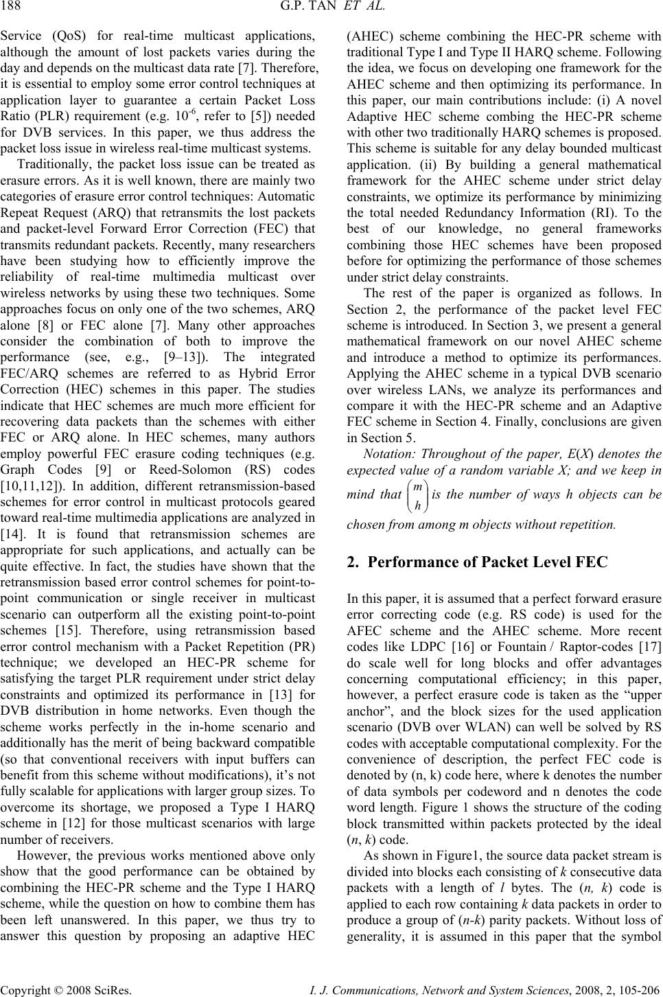 188 G.P. TAN ET AL. Copyright © 2008 SciRes. I. J. Communications, Network and System Sciences, 2008, 2, 105-206 Service (QoS) for real-time multicast applications, although the amount of lost packets varies during the day and depends on the multicast data rate [7]. Therefore, it is essential to employ some error control techniques at application layer to guarantee a certain Packet Loss Ratio (PLR) requirement (e.g. 10-6, refer to [5]) needed for DVB services. In this paper, we thus address the packet loss issue in wireless real-time multicast systems. Traditionally, the packet loss issue can be treated as erasure errors. As it is well known, there are mainly two categories of erasure error control techniques: Automatic Repeat Request (ARQ) that retransmits the lost packets and packet-level Forward Error Correction (FEC) that transmits redundant packets. Recently, many researchers have been studying how to efficiently improve the reliability of real-time multimedia multicast over wireless networks by using these two techniques. Some approaches focus on only one of the two schemes, ARQ alone [8] or FEC alone [7]. Many other approaches consider the combination of both to improve the performance (see, e.g., [9–13]). The integrated FEC/ARQ schemes are referred to as Hybrid Error Correction (HEC) schemes in this paper. The studies indicate that HEC schemes are much more efficient for recovering data packets than the schemes with either FEC or ARQ alone. In HEC schemes, many authors employ powerful FEC erasure coding techniques (e.g. Graph Codes [9] or Reed-Solomon (RS) codes [10,11,12]). In addition, different retransmission-based schemes for error control in multicast protocols geared toward real-time multimedia applications are analyzed in [14]. It is found that retransmission schemes are appropriate for such applications, and actually can be quite effective. In fact, the studies have shown that the retransmission based error control schemes for point-to- point communication or single receiver in multicast scenario can outperform all the existing point-to-point schemes [15]. Therefore, using retransmission based error control mechanism with a Packet Repetition (PR) technique; we developed an HEC-PR scheme for satisfying the target PLR requirement under strict delay constraints and optimized its performance in [13] for DVB distribution in home networks. Even though the scheme works perfectly in the in-home scenario and additionally has the merit of being backward compatible (so that conventional receivers with input buffers can benefit from this scheme without modifications), it’s not fully scalable for applications with larger group sizes. To overcome its shortage, we proposed a Type I HARQ scheme in [12] for those multicast scenarios with large number of receivers. However, the previous works mentioned above only show that the good performance can be obtained by combining the HEC-PR scheme and the Type I HARQ scheme, while the question on how to combine them has been left unanswered. In this paper, we thus try to answer this question by proposing an adaptive HEC (AHEC) scheme combining the HEC-PR scheme with traditional Type I and Type II HARQ scheme. Following the idea, we focus on developing one framework for the AHEC scheme and then optimizing its performance. In this paper, our main contributions include: (i) A novel Adaptive HEC scheme combing the HEC-PR scheme with other two traditionally HARQ schemes is proposed. This scheme is suitable for any delay bounded multicast application. (ii) By building a general mathematical framework for the AHEC scheme under strict delay constraints, we optimize its performance by minimizing the total needed Redundancy Information (RI). To the best of our knowledge, no general frameworks combining those HEC schemes have been proposed before for optimizing the performance of those schemes under strict delay constraints. The rest of the paper is organized as follows. In Section 2, the performance of the packet level FEC scheme is introduced. In Section 3, we present a general mathematical framework on our novel AHEC scheme and introduce a method to optimize its performances. Applying the AHEC scheme in a typical DVB scenario over wireless LANs, we analyze its performances and compare it with the HEC-PR scheme and an Adaptive FEC scheme in Section 4. Finally, conclusions are given in Section 5. Notation: Throughout of the paper, E(X) denotes the expected value of a random variable X; and we keep in mind that ⎟ ⎟ ⎠ ⎞ ⎜ ⎜ ⎝ ⎛ h mis the number of ways h objects can be chosen from among m objects without repetition. 2. Performance of Packet Level FEC In this paper, it is assumed that a perfect forward erasure error correcting code (e.g. RS code) is used for the AFEC scheme and the AHEC scheme. More recent codes like LDPC [16] or Fountain / Raptor-codes [17] do scale well for long blocks and offer advantages concerning computational efficiency; in this paper, however, a perfect erasure code is taken as the “upper anchor”, and the block sizes for the used application scenario (DVB over WLAN) can well be solved by RS codes with acceptable computational complexity. For the convenience of description, the perfect FEC code is denoted by (n, k) code here, where k denotes the number of data symbols per codeword and n denotes the code word length. Figure 1 shows the structure of the coding block transmitted within packets protected by the ideal (n, k) code. As shown in Figure1, the source data packet stream is divided into blocks each consisting of k consecutive data packets with a length of l bytes. The (n, k) code is applied to each row containing k data packets in order to produce a group of (n-k) parity packets. Without loss of generality, it is assumed in this paper that the symbol  A NOVEL ADAPTIVE HYBRID ERROR CORRECTION SCHEME FOR 189 WIRELESS DVB SERVICES Copyright © 2008 SciRes. I. J. Communications, Network and System Sciences, 2008, 2, 105-206 size is always one byte for the FEC code. The coding block is transmitted by packets in the form of columns. Assuming exactly one packet per column, the receiver only needs to correctly receive any k of these n columns to be able to recover all the k data packets. Therefore, the PLR performance of this scheme is exactly the same as the performance of the ideal (n, k) code. Figure 1. Applying ideal (n, k) code at the packet level, which forms an FEC coding block in n packets To simplify the analysis, in this paper, the packet loss channel in wireless networks is modeled as the erasure error channel with independently and identically distributed (i.i.d.) losses with uniform distribution. Firstly, we define the probability of b packets lost in a sequence of n packets in the erasure channel with link PLR of Pe as P(b,n,Pe). Since all of the n packets have the same loss probability of Pe, the probability P(b,n,Pe) is given by: b e bn ee PP b n PnbP )()1(),,( − − ⎟ ⎟ ⎠ ⎞ ⎜ ⎜ ⎝ ⎛ = (1) In the following, let the random variable Ik represent the number of data packets lost in a group of k data packets after decoding using the (n,k) code. Upon the definition of Ik, the PLR performance of the (n,k) code actually can be computed by E(Ik)/k. That means we only need to calculate the expected value of I k. To obtain E(Ik), we firstly have to find out the Probability Distribution Function (PDF) of Ik. For the convenience of description, here we assume that the value of Ik is i and there are b packets lost in a group of n packets. If b is not more than n-k, the number of packets received in a group of n packets will be at least k so that all of the k data packets can be recovered. Obviously, the value of Ik is zero in this case. On the other hand, if the value of Ik is more than zero, there are exactly i (where 1≤i≤k) data packets lost in the group of n packets after decoding with the (n,k) code. It indicates that at least max (n-k+1,i) and at most (n-k+i) packets are lost in this group. That is, the value of b is in the range of [max(n-k+1,i), n-k+i]. Let Pd(i,b) denote the probability of i data packets lost under the condition of b packets lost in a group of n packets. In other words: Among all of the b packets lost in the group, there are i data packets lost among all of the k data packets and b-i parity packets lost among all of the n-k parity packets. Let Pd(i,b) denote the probability of i data packets lost among all of those b packets lost. Note that all packets in a group of n packets have the same loss probability in the i.i.d erasure error channel, we thus have: ⎟ ⎟ ⎠ ⎞ ⎜ ⎜ ⎝ ⎛ ⎟ ⎟ ⎠ ⎞ ⎜ ⎜ ⎝ ⎛ − − ⎟ ⎟ ⎠ ⎞ ⎜ ⎜ ⎝ ⎛ = b n ib kn i k biPd),( (2) Based on the analysis above, using (1) and (2), we then obtain the PDF of Ik as follows: .,...,2,1),,(),,()I(Pr ),1max( kibiPPnbPi de ikn iknb k=== ∑ +− +−= (3) Following (3), the expected value of Ik thus can be calculated by: ∑∑ = +− +−= ×= k i ikn iknb dek biPPnbPiE 1),1max( ),(),,()I( (4) Finally, when the ideal (n,k) code is applied in the erasure error channel with link PLR of Pe, the PLR achieved will be: ∑∑ = +− +−= ×= = k i ikn iknb de k kn biPPnbPi k k E PLR 1),1max( ),( ),(),,( 1 )I( (5) From the analysis above it follows that (5) is also the PLR performance of the packet level FEC scheme with an ideal (n,k) code over the erasure error channel with link PLR of Pe. 3. Proposed AHEC Scheme In this section, first, we introduce the system model of the proposed Adaptive Hybrid Error Correction (AHEC) scheme combing the HEC-PR scheme and the traditional Type I and Type II HARQ schemes. Then, we present a mathematical framework for the AHEC scheme. Based on the mathematical framework, we finally present how to design the optimum parameters for the AHEC scheme guaranteeing a certain PLR requirement under strict delay constraints. At the beginning, for the AHEC scheme using retransmission technique, rather than focus on a particular transport protocol, we shall consider a generic retransmission based scheme with the following features: y A selective repetition, NACK-only retransmission scheme is used; y The transmitter multicasts the required packets immediately to all receivers upon getting a NACK. In addition, to simplify the analysis we make the  190 G.P. TAN ET AL. Copyright © 2008 SciRes. I. J. Communications, Network and System Sciences, 2008, 2, 105-206 following assumptions for the retransmission based schemes: y The feedback channel for NACKs is assumed to be error-free. Since NACKs are control messages and real systems usually provide mechanisms to guarantee the reliable transmission of control signals, this assumption is realistic in many cases. Or alternately, the effect of NACKs loss can be overcome by setting a margin for the PLR performance of the AHEC scheme. y All of the receivers experience erasure error channel with i.i.d of uniform distribution. This means we do not consider the effect of temporal correlation of the channel and spatial correlation among different receivers in this paper; this, however, is actually ongoing work, which will come soon in [18]. Now, the essential symbols are defined and summed up in Table 1. Table 1. Symbols definitions Symbol Definition PLRtarget target PLR requirement Dtarget target Delay requirement Pe (j) the PLR for the j-th receiver RTT(j) average round trip time for the j-th receiver, one way delay is RTT(j) /2 Nrecv number of receivers in the multicast scenario1 ts the average interval between two continuous original data packets at the transmitter2 trw the average waiting time at each receiver, which is the time between the detection of a packet loss and the time when the corresponding NACK is sent3 tsw the average waiting time at the transmitter, which is the time between receiving a NACK message and the time when the corresponding packets required by the NACK message are retransmitted tlp(j) the duration from the time the j-th receiver detected packets lost to the time it possibly receives the required packets, which is RTT(j)+ tsw+ trw 3.1. System Model From [13] we know that the HEC-PR scheme has a major drawback: the total needed RI raises with the increase of the group size linearly in a multicast scenario, because the receivers can not share common retransmission packets for repairing different missing data packets. For overcoming this shortage, we proposed a Type I HARQ scheme in [12] for those multicast 1The parameter Nrecv is also viewed as the group size in a multicast scenario in this paper. 2 In this paper, it is assumed that the interval is same to the retransmission interval for different copies of retransmission packets. 3 The average waiting time at each receiver is identical due to the same process for all of the receivers. scenarios with large number of receivers. However, the works mentioned above only show that good performance can be obtained by combining the HEC-PR scheme and the Type I HARQ scheme, while the question on how to combine them has been left unanswered. In this paper, we thus propose an adaptive HEC (AHEC) scheme combining the HEC-PR scheme with traditional Type I and Type II HARQ scheme. The system model of the AHEC scheme is shown in Figure 2. As shown in this figure, the transmitter firstly transmits encoding blocks to all receivers using the packet level FEC code. Here it is assumed that perfect forward erasure error correction code (e.g. Reed- Solomon code.) is used and the number of source data packets is k in one encoding block. That is, upon received any k packets of one encoding block, the receiver can recover all the data packets. Otherwise, the receiver will send Negative-Acknowledgments (NACKs) to the transmitter for repairing the missing data packets. Now we explain the AHEC scheme in more detail: 1) First, the sender sends a certain amount of redundant packets or only k data packets to all of the receivers immediately with the first transmission. Especially, when k is set to one then the redundant packets during all of the retransmissions are always multiple copies of source data packets; this scheme acts actually as the HEC-PR scheme proposed in [13]. 2) If any k packets of one encoding block are received, the receiver then can recover all of the k data packets and forward them to the application immediately. Otherwise, the receiver will transmit a NACK message to the sender to require essential redundant packets for recovering all of the missing data packets. 3) Upon getting the first NACK message for one encoding block during each retransmission round, the sender will multicast a certain number of redundant packets to all of receivers immediately with one copy (or multiple copies) of these retransmission packets; afterwards, if other NACKs for the same encoding block are received, the sender will decide if multicast more redundant packets to all of the receivers according to the requirements of NACKs. That is, if those later NACKs require more redundant packets than the fist NACK message, the sender will multicast further redundant packets to all of receivers immediately; otherwise, the sender will neglect those NACKs. Similarly, all of receivers can do suppression of NACKs by this rule if those NACKs are transmitted by multicasting mode. From above introduction, we know that the performance of the AHEC scheme mainly depends on three parameters: the number of retransmission rounds; the number of redundant packets with the first transmission and retransmissions and the number of copies of redundant packets with retransmissions. Note that if the redundant packets are parity packets, they  A NOVEL ADAPTIVE HYBRID ERROR CORRECTION SCHEME FOR 191 WIRELESS DVB SERVICES Copyright © 2008 SciRes. I. J. Communications, Network and System Sciences, 2008, 2, 105-206 should not be repeated, but possibly more new parity packets should be retransmitted. The remaining task is to find out those suitable parameters of the AHEC scheme for satisfying the strict QoS requirements of real-time services. In the following section, we will present a mathematical framework for analyzing the performances of the AHEC scheme. 3.2. Performance Analysis Theoretically, we should also design parameters for the AHEC scheme with each receiver separately as for HEC-PR scheme as in [13]. However, it is very hard to implement for practical systems if different FEC codes used for different receiver with the first transmission. To simplify the implementation, therefore, the AHEC scheme will adopt the same parameters for every receiver. Since the assumed erasure code is perfect, a suitable choice of the code rate can guarantee that all receivers with their different channel conditions can be served, so this simplification doesn’t negatively influence the overhead. Figure 2. System model of the AHEC scheme The parameters for the AHEC scheme with retransmissions are defined as follows: y k: the number of source data packets in one encoding block; y Np: the number of redundant packets in one encoding block with the first transmission; y Ncc: a constant coefficient, which is the number of additional new redundant packets for one encoding block with different retransmission rounds; y Nblk: the number of packets in one block with the first transmission, which is k+Np; y Nrr,max: the maximum possible number of retransmission rounds; y q rt N: the number of copies for each retransmission packet at the sender during the q-th retransmission round, where max, 1rr Nq ≤≤ ; y Nrt,max: the maximum possible number of copies for each retransmission packet at the sender, which is: ∑ = = max, 1 max, rr N q q rtrt NN . For the convenience of description, two additional random variables are defined as follows: y Ik(j,w): a random variable representing the number of missing data packets for the j-th receiver in one encoding block of k source data packets after experiencing w retransmission rounds, where 1≤w≤ Nrr,max; y Nreq(j): a random variable representing the number of redundant packets required to receive for recovering all of the k data packets in one block for the j-th receiver in the first retransmission round, where 0≤Nreq(j)≤k. Based on above definitions, we now begin to analyze the PLR performance for one receiver (without loss of generality, it is assumed to be the j-th receiver) with the AHEC scheme. To derive the PLR performance of the AHEC scheme for the j-th receiver, we need to calculate the expected value of the number of missing data packets in one encoding block of k source data packets after the retransmission packets experiencing w (0≤w≤Nrr,max) retransmission rounds. The PLR performance of the AHEC scheme for the j-th receiver then can be calculated as: E(Ik(j,w))/k, which is the final PLR at the j-th receiver after all of the retransmission packets experienced w retransmission rounds. Note that if the w is set to zero, the AHEC scheme acts as the AFEC scheme. In the following, it is always assumed that the w is more than zero for the AHEC scheme. First of all, in order to recover all of the missing data packets for each receiver that received fewer than k packets for one block, at least Nreq,max redundant packets need to be retransmitted at the sender: ))(),...,2(),1(max( max, recvreqreqreqreq N Ν Ν Ν = Ν (6) Obviously, Nreq,max is also a random variable. Since it is assumed that the feedback channel is error-free, the random variable Nreq,max always reflects the true maximum number of lost packets in one block for the worst receiver. Before calculating the average number of lost data packets in one block for the j-th receiver, here we define two useful probabilities: one is the PDF of Nreq,max (i.e. Pr(Nreq,max=i)), which is denoted by Pi Nreq,max; the other is the probability of Nreq,max of i in the condition of Nreq (j) of c (i.e. Pr(Nreq,max=i|Nreq(j)=c)), which is denoted by Preq (i,c,j). The detail derivation on these two important probabilities is attached in the appendix. Secondly, according to the definitions above, the parameter Ncc is always constant for any random value of Nreq,max in each retransmission round. Now let symbol “r” denote the number of received redundant packets within w retransmission rounds. Note that multiple copies of a retransmission packet received are counted as one redundant packet received. We then define the probability of r different redundant packets received after all of the m=Nreq,max+Ncc different redundant packets experiencing w retransmission rounds for the j- th receiver as Precv(r,m,w,Pe(j)). Note that the loss probably of each retransmission packet within w retransmission rounds will be∑ = w q q rt N ejP1 ))(( . We thus have:  192 G.P. TAN ET AL. Copyright © 2008 SciRes. I. J. Communications, Network and System Sciences, 2008, 2, 105-206 rm N e r N eerecv w q q rt w q q rt jPjP r m jPwmrP − ⎟ ⎟ ⎟ ⎠ ⎞ ⎜ ⎜ ⎜ ⎝ ⎛∑ ⎟ ⎟ ⎟ ⎠ ⎞ ⎜ ⎜ ⎜ ⎝ ⎛∑ − ⎟ ⎟ ⎠ ⎞ ⎜ ⎜ ⎝ ⎛ === 11 ))(())((1))(,,,( (7) For the convenience of description, in the following, we define some temp symbols as follows: symbol ‘i’ denotes the number of data packets lost in a group of Nblk packets for the j-th receiver in the first transmission; symbol ‘b’ denotes the total number of packets lost in a group of Nblk packets for the j-th receiver in the first transmission; symbol ‘s’ denotes the number of redundant packets sent at the sender in the first retransmission round; symbol ‘m’ denotes the number of redundant packets received during the retransmission round for the j-th receiver. Now, as introduced in Section 2, we also adopt Pd(i,b) to denote the probability of i data packets lost under the condition of b packets lost in a group of n packets. The conditional probability Pd(i,b) also can be calculated by (2). Finally, we can derive the PDF of Ik(j,w) based on those probabilities introduced above. Now we assume that the value of Ik(j,w) is i (where 1≤i≤k), which means that there are i data packets lost after experiencing w retransmission rounds. Obviously, it indicates that there are b (where max(Np+1, i)≤b≤Np+i) packets lost in the block of Nblk packets for the j-th receiver in the first transmission. According to the AHEC scheme, this receiver will require b –Np redundant packets for retransmission at the sender for recovering the missing i data packets. However, at the same time, the sender will possibly send s (where b–Np+Ncc≤s≤k+Ncc) parity packets due to combining all of the NACKs from overall receivers in the multicast scenario. Finally, note that the receiver obtained k+Np–b+m packets at the end of the w retransmission rounds. Note that the data packets lost only happen under the condition of k+Np–b+m being less than k, which means the value of m will be less than b–Np. Based on above analysis, using (2), (7) and the probability Preq(m,c,j) (See Appendix), the PDF of Ik(j,w) then can be expressed as this form: ⎟ ⎟ ⎠ ⎞ ⎜ ⎜ ⎝ ⎛ −− ×== ∑ ∑∑ −− = + += + +−= 1 0 ),1max( ))(,,,(),,( ),()),(I(Pr p p p cc ccp Nb m erecvpccreq iN iNb Nk NNbs dk jPwsmPjNbNsP biPiwj (8) where i=1,2,…,k. Following (8), we then obtain the expected value of Ik(j,w): () ∑ = =Ι×= k i kk iwjiwjE 1 ),(Pr)),(I( (9) Relying on (9) and substituting (7) and (8) into (9), we then obtain the PLR performance of the AHEC scheme for the j-th receiver with Nrr,max retransmission rounds immediately: ⎟ ⎟ ⎠ ⎞ ⎜ ⎜ ⎝ ⎛− ⎟ ⎟ ⎠ ⎞ ⎜ ⎜ ⎝ ⎛ ×−− ×= ⎟ ⎟ ⎟ ⎠ ⎞ ⎜ ⎜ ⎜ ⎝ ⎛∑∑ − ⎟ ⎟ ⎠ ⎞ ⎜ ⎜ ⎝ ⎛ ×−− ×= ⎟ ⎟ ⎠ ⎞ ⎜ ⎜ ⎝ ⎛ −− ×= = ∑ ∑∑ ∑ ∑ ∑∑ ∑ ∑ ∑∑ ∑ −− = − = + += + +−= −− = − = + += + +−= −− = = + += + +−= == 1 0 1),1max( 1 0 1),1max( 1 0 max, 1),1max( max, max, )))((()))((1( ),,(),( 1 )))((()))((1( ),,(),( 1 ))(,,,(),,(),( 1 )),(I( ),( max,max, max, 1 max, 1 p rtrt p p cc ccp p rr N q q rt rr N q q rt p p cc ccp p p p cc ccp Nb m ms N e m N e pccreqd k i iN iNb Nk NNbs Nb m ms N e m N e pccreqd k i iN iNb Nk NNbs Nb m errrecvpccreqd k i iN iNb Nk NNbs rrk rrAHEC jPjP m s jNbNsPbiP i k jPjP m s jNbNsPbiP i k jPNsmPjNbNsPbiP i k k NjE NjPLR (10) For simplifying the description, we define a vector as follows: j e P v =[Pe(1), P e (2),…, P e (j-1), Pe (j+1),…, Pe (Nrecv)]. By observing (10), we can find that it is actually a function with these parameters: k, Np, Ncc, rt N v , Pe(j) and j e P v , which is denoted by )),(,,,,,( max, , j eerecvrtccp AHECPLR PjPNNNNkf v in this paper. In the following, let’s consider the total needed RI with the AHEC scheme, which includes two parts: one is the common part for all of the receivers in the first transmission, which is Np/k; the other is the part in the retransmissions, which is caused by the retransmissions of redundant packets for all of the receivers. For the convenience of calculation, we divide the second part into two subparts: one is the needed RI in the first retransmission round (denotes by RIAHEC-I); the other part is the needed RI in the retransmission rounds (denotes by RIAHEC-II) of from the second retransmission round to the Nrr,max retransmission round. First, considering the calculation of RIAHEC-I, note that the value i (where 0≤i≤k) of Nreq,max means that )( 1 ccrt NiN+× redundant packets will be retransmitted in the first retransmission round at the sender. Using the PDF of Nreq,max (See Appendix), thus, the RIAHEC-I is given by: ∑ = −×+×= k i i NccrtIAHECreq PNiN k RI 1 1 max, )( 1 (11) Then, considering the calculation of RIAHEC-II, to simplify the analysis, here it is assumed that there is only one Equivalent Receiver (ER) in the multicast scenario with Nrecv receivers and the loss probability of each  A NOVEL ADAPTIVE HYBRID ERROR CORRECTION SCHEME FOR 193 WIRELESS DVB SERVICES Copyright © 2008 SciRes. I. J. Communications, Network and System Sciences, 2008, 2, 105-206 retransmission packet for the ER ise P, where e Pis the average link PLR and defined as: recv N j e eN jP P recv ∑ = =1 )( (12) To derive RIAHEC-II, let’s note the following fact: if the ER requires i (1 ≤ i ≤ k) redundant packets for repairing missing data packets in the q-th (2 ≤ i ≤ Nrr,max) retransmission round, it indicates that the ER required j (i ≤ j ≤ k) redundant packets in the first retransmission round and received only j–i redundant packets in the group of Ncc+j retransmission redundant packets in all of the previous q–1 retransmission rounds. Therefore, using the PDF of Nreq,max and (7), we can obtain the probability of the ER requiring i redundant packets in the q-th retransmission round, i.e.: ),1,,( max, eccrecv k ij j NPqjNijPP req −+− ∑ = . Then the calculation of RIAHEC-II can be written as this form: ⎟ ⎟ ⎠ ⎞ ⎜ ⎜ ⎝ ⎛−+− ×+×= ∑ ∑∑ = == − ),1,,( )( 1 max, max, 21 eccrecv k ij j N N q k i cc q rtIIAHEC PqjNijPP NiN k RI req rr (13) As a result, by substituting (7) into (13) and then combining (11) and (13), the total needed RI for the AHEC scheme with Nrr,max retransmission rounds is given by: ⎟ ⎟ ⎟ ⎟ ⎠ ⎞ ⎜ ⎜ ⎜ ⎜ ⎝ ⎛ ⎟ ⎟ ⎟ ⎠ ⎞ ⎜ ⎜ ⎜ ⎝ ⎛∑ − ⎟ ⎟ ⎟ ⎠ ⎞ ⎜ ⎜ ⎜ ⎝ ⎛∑ ⎟ ⎟ ⎠ ⎞ ⎜ ⎜ ⎝ ⎛ − + ×+× +×+×+= ++= −+ = == = −− − = − = ∑ ∑∑ ∑ ij N e iN N e cc k ij j N N q k i cc q rt k i i Nccrt p IIAHECIAHEC p AHEC q g g rt cc q g g rt req rr req PP ij jN P NiN k PNiN kk N RIRI k N RI 1 1 1 1 max, max, max, )(1)( )( 1 )( 1 21 1 1 (14) Now we define two vectors e P v =[Pe(1), Pe (2),…, P e (Nrecv)] and= rt N v [max, ,...,, 21 rr N rtrtrt NNN ]. By observing (14), we can also find that the RI performance of the AHEC scheme actually is a function with such these parameters: k, N p, Ncc, rt N v , e Pand e P v , which is denoted by: ),,,,,,( ,eerecvrtccp AHECRIPPNNNNkf v v in this paper. 3.3. Optimization of the AHEC Scheme In this section, we will propose a method to design suitable parameters for the AHEC scheme. Note that all of the receivers share identical parameters for this scheme. Therefore, if the AHEC scheme can guarantee the QoS requirements for the worst receiver, it can also guarantee the same QoS requirements for every receiver in the multicasting scenario. Without loss of generality, it is assumed the first receiver is the one with the worst situation in a multicasting scenario. In other words, the first receiver has the largest link PLR and the largest RTT. Our remaining task is to design suitable parameters of the AHEC scheme, which will satisfy a certain PLR requirement for the first receiver under strict delay constraint with minimum total needed RI. First of all, it is known that the delay requirement will limit the number of data packets in one block and the number of retransmissions. In the following, we will derive the boundary of the two parameters Nrr,max and k based on the strict delay constraint. For those retransmission packets in the first receiver, the maximum possible end-to-end delay includes four parts: the one-way delay in the first transmission (which is RTT(1)/2); Nrr,max of two-way delays in the retransmission rounds (which is Nrr,max×tlp(1)); the decoding delay caused by the length of encoding block (which is (k×ts)) and total number of intervals for the copies of retransmission packets (which is (Nrt,max×ts)). Thus, for those retransmission packets of the first receiver, the maximum possible end-to-end delay must satisfy: targetmax,max, D)()1( 2 )1( ≤×++×+ srtlprrtNktN RTT (15) Because the value of (k + Nrt,max) is at least 2 for the AHEC scheme, the maximum allowable number of retransmission rounds is constrained by: ⎥ ⎥ ⎥ ⎥ ⎦ ⎥ ⎢ ⎢ ⎢ ⎢ ⎣ ⎢×−− =)1( 2 2 )1( D ˆtarget max, lp s rr t t RTT N (16) where ⎣ ⎦ x denotes the largest integer not greater than x. Therefore, for the AHEC scheme the parameter Nrr,max will be limited in the range of between one andmax, ˆrr N. Then, we define the length of k with w retransmission rounds and maximum v copies of retransmission packets as k(w,v), which is given by:  194 G.P. TAN ET AL. Copyright © 2008 SciRes. I. J. Communications, Network and System Sciences, 2008, 2, 105-206 ⎥ ⎥ ⎥ ⎥ ⎦ ⎥ ⎢ ⎢ ⎢ ⎢ ⎣ ⎢×−−×− = s slp t tv RTT tw vwk2 )1( )1(D ),( target (17) where 1≤w≤max, ˆrr N and v≥w. Note that in (17) the parameter k will only rely on the parameters w and v if tlp(1), ts, RTT(1) and Dtarget are fixed. To simplify the design, we assume that the parameters tlp(1), ts and RTT(1) is always fixed in a scenario and Dtarget is also constant for the given QoS requirements. Therefore, the length of k will only depend on the parameters w and Nrt,max.. Considering practical implementation, actually, we can set an upper band of the maximum possible value for Nrt,max (denotes bymax, ~ rt N, note that it is not less than max, ˆrr Ndue to the practical consideration). Theoretically, the value of max, ~ rt N can be set to infinite. However, as shown in (14), the total needed RI increase with the increasing of max, ~ rt N significantly. Therefore, the minimum total needed RI usually can be acquired under a small value ofmax, ~ rt N. Now the parameter rt N v can be limited in a small finite space max,rr N Φ(i.e. max,rr N rt NΦ∈ v), which is: [] ⎪ ⎭ ⎪ ⎬ ⎫ ⎪ ⎩ ⎪ ⎨ ⎧ ≥≥≥ ≤ ∑ =Φ= 1,1 ~ ,...,, max, max, 1 21 max, max, max, iNr Nr rrr rri rt N kk N N rr rr rr (18) where: max,max, ˆ 1rrrr NN ≤≤ Note that the parameter Nrt,max of the AHEC scheme is actually the sum of all of the elements in the vector rt N v , which is denoted by sum(rt N v) here. Depending on the PLR and RI performance analyzed for the AHEC scheme in Subsection 3.2, our optimization problem thus can be written as the following form: () eerecvrtccprtrrAHECRI N optAHEC PPNNNNNNkf RI rr N rt vvv v ,,,,,)),sum(,( minarg max,, , max, Φ∈ = Subject to: max,max, ˆ 1rrrr NN ≤≤ ( ) target 1 max,, PLR ),1(,),sum(,,)),sum(,( ≤ eerecvrtccprtrrAHECPLR PPNNNNNNkf v vv (19) By solving (19) with traversing the full space, we thus can obtain the optimal parameters for the AHEC scheme: k, Np, Ncc, Nrr,max and rt N v. Remarks: If k is set to one, the AHEC scheme acts as a pure HEC-PR scheme; If k is set to more than one and Np is set to more than zero, the AHEC scheme acts as the traditional Type I HARQ scheme; If k is set to more than one and Np is set to zero, the AHEC scheme acts as the traditional Type II HARQ scheme. As a result, the AHEC scheme can choose the best scheme automatically among the HEC-PR scheme, traditional Type I and Type II HARQ scheme by solving (19). 4. Analysis Results In this section, we firstly analyze the performances of three schemes over an erasure error channel: the HEC- PR scheme, the AFEC scheme and the AHEC scheme, respectively; and then compare them with each other. Then, we study the effect of the parameter k in the AHEC scheme. For the convenience of comparing different schemes fairly, we make some assumptions as follows: the entire receivers experience the i.i.d erasure channel with the same level of original link PLR; the three schemes use identical system parameters with the same QoS requirements for the PLR and the same latency. In this case, we consider DVB services over wireless home networks with a group size of less than 7, RTT of less than 15ms and a wireless link PLR of up to 10% when the video multicast data rate is more than 500Kbps [7]. The target PLR requirement is set to 10-6 under the strict delay constraint of 100ms (refers to [5]). However, it should be clear that the proposed AHEC scheme is suitable for any wireless multicasting scenario under strict delay boundary. Now we apply the three schemes in a typical scenario with the common system parameters, which are summarized in Table 2. Table 2. System parameters PLR Requirement: PLRtarget 10-6 Latency Constraint: Dtarget 100ms Multimedia Data Rate: 4Mbps Packet Loss Model GE Model RTT 15ms trw+tsw: 0ms Encoding Packet Length: Nsymb 1250bytes Original Average Link PLR: Pe 10-3~10-1 Actually, the following theoretical analysis results have been accompanied by simulations with ns-2 [19]. However, those simulation results are not further explained in this paper due to the fact theory matches simulation very well. 4.1. Optimization Results In the following, we will design the optimum parameters for the AHEC scheme for this typical scenario and then  A NOVEL ADAPTIVE HYBRID ERROR CORRECTION SCHEME FOR 195 WIRELESS DVB SERVICES Copyright © 2008 SciRes. I. J. Communications, Network and System Sciences, 2008, 2, 105-206 compare it with the HEC-PR scheme and the AFEC scheme. First, to meet the latency requirement we can obtain the maximum allowable number of retransmission rounds max, ˆrr N with the AHEC scheme by solving (16), which are at most five. Then, since it is found that the optimum value for the parameter Nrt,max is usually much less than five by our numerical calculations for this case, the maximum value of Nrt,max is set to five (i.e. 5 ~ max, = rt N) to make sure that the optimum results of the AHEC scheme can be acquired by the searching algorithm. Note that in the traditional Type I and Type II HARQ schemes, multiple copies of a parity packet only can be counted as one redundant packet at the receivers. For the consideration of efficiency, we should only adopt new parity packets instead of multiple copies of redundant packets at each retransmission round. For this reason, the parameters of the AHEC scheme will always satisfy Nrt,max =Nrt,max (i.e. max, 1,1rr q rt NqN ≤≤≡) in the case of k>1. Based on these boundaries, the optimum parameters of AHEC with different link PLR and small group size can be obtained by solving (19). Parts of the optimum parameters are shown in Table 3 and 4. Table 3. Optimum parameters of the AHEC scheme with Nrecv=2 Optimum Parameters of the AHEC scheme rt N v Average Link PLR k Np Ncc 1 rt N 2 rt N 3 rt N4 rt N 0.001 23 0 0 1 1 - - 0.01 16 0 0 1 1 1 - 0.03 9 0 0 1 1 1 1 0.05 9 0 0 1 1 1 1 0.07 1 0 0 1 1 1 2 0.09 1 0 0 1 1 1 2 0.10 16 2 1 1 1 1 - Table 4. Optimum parameters of the AHEC scheme with average link PLR of 0.06 Optimum Parameters of the AHEC scheme rt N v Nrecv k Np Ncc 1 rt N 2 rt N 3 rt N4 rt N 1 1 0 0 1 1 1 1 2 1 0 0 1 1 1 1 3 23 2 1 1 1 - - 4 23 2 1 1 1 - - 5 23 3 1 1 1 - - 6 23 3 1 1 1 - - 7 23 3 1 1 1 - - From these two tables, we can see that the AHEC scheme can automatically choose the most suitable scheme according to current group size and average link PLR among the HEC-PR scheme, the Type I HARQ scheme and the Type II HARQ scheme. For example, as shown in Table 3, the AHEC scheme will act as the Type II HARQ scheme if the real-time multicast scenario is with Nrecv=2 and average link PLR of 0.05. Similarly, as shown in Table 4, the AHEC scheme acts as the HEC-PR scheme if the scenario is with Nrecv=2 and average link PLR of 0.06; and it will act as the Type I HARQ scheme if the scenario is with Nrecv=7 and average link PLR of 0.06. Figure 3. The total needed RI with different schemes 4.2. Performance Comparisons Upon those optimum results shown in Table 3 and Table 4, now we obtain the total needed RI by (14) of the AHEC scheme with different group size, which are shown in Figure 3. For comparing the performances among different schemes, Figure 3 also show the total needed RI with the HEC-PR scheme and the AFEC scheme. Note that the AFEC scheme is actually a special case of the AHEC scheme with Np=0 and Nrr,max=0. From this figure, we can see that the total needed RI of the HEC-PR scheme increases with the increase of the number of receivers significantly but not strict linearly. The reason is clear: although all of the receivers are independent, they also can recover some common missing packets by retransmitting a small part of identical packets with the HEC-PR scheme. As a matter of fact, the probability of sharing identical packets among different receivers will increase with the increase of the number of receivers. This leads to the total needed RI of the HEC-PR scheme increase with the number of receivers significantly but not strict linearly. In other words, the speed of the increase of the total needed RI will slow down with the increase of the number of receivers. Additionally, as shown in this figure, the AHEC scheme always outperform the HEC-PR scheme and the AFEC scheme, because it can choose the best scheme automatically among different HEC schemes. However, from this figure, we also can see that the performance of  196 G.P. TAN ET AL. Copyright © 2008 SciRes. I. J. Communications, Network and System Sciences, 2008, 2, 105-206 the HEC-PR scheme is very close to the AHEC scheme when the number of receivers is no more than two or the average link PLR is less than 10-2. Because the implementation of the HEC-PR scheme is very simple due to without any encoding and decoding algorithm, the HEC-PR scheme should be considered for such as those real-time multicast services with small group size and small average link PLR. 4.3. The Effect of the Parameter k Finally, we study the effect of the parameter k in the AHEC scheme in this section. For the convenience of analysis, we searched for the optimum parameters for the AHEC scheme with the fixed parameters Nrecv=5 and Nrr,max=2 under different average link PLR of 0.01,0.05 and 0.10. Actually, on the effect of the k, the tendency is similar for any average link PLR. Here we only take three typical examples to demonstrate the tendency of its effect. Part of those optimum parameters is listed in the Table 5. Table 5. Optimum Parameters of the AHEC Scheme with Nrecv=5 and Nrr,max=2 k 20 40 80 120 160200 Np 1 1 1 1 2 2 PLR=0.01 Ncc 0 0 0 0 0 0 Np 2 3 6 8 10 12 PLR=0.05 Ncc 1 1 1 1 1 1 Np 4 7 12 16 21 25 PLR=0.10 Ncc 2 2 2 2 2 2 Note that although here we only show the results for the AHEC scheme with the length of k being less than 200, it should be clear that the AHEC scheme is suitable for any length of k upon requirements; moreover, the higher k is employed by the ideal erasure error code, the more efficient code rate can be adopted. From this table, we can see that the parameter Ncc is always invariable under certain average link PLR. That is, we only need to change the parameter Np for the AHEC scheme according to different value of k under certain average link PLR. Note that the variable value of k means different multimedia data rate under certain delay constraints if the packet size is constant. Obviously, this feature of the AHEC scheme can simplify its implementation in real-time multicast scenarios with variable source data rate. Upon those optimum parameters with different length of k, the total needed RI of the AHEC scheme is obtained and shown in Figure 4. From this figure, we can see that the total needed RI decreases significantly when the parameter k increases from 10 to 60. When k is more than 60, however, this parameter has only a little effect on the performance of the AHEC scheme. Note that different k values mean different delay constraints or different source data rates if the packet size is fixed. Therefore, under certain delay constraints with fixed packet size, the higher the multicast source data rate is, the better performance can be achieved in the AHEC scheme. Moreover, since the stable good performance can be obtained if the parameter k is more than 60, a suitable fixed short length of k (≥60) can be always adopted when the data rate is high enough to provide good delay performance. On the other hand, the parameter k is only associated with the delay constraints if both the source data rate and the packet size are fixed: to guarantee a certain PLR requirement, shorter delay constraints the system has, shorter length of the parameter k in the AHEC scheme has to be adopted so that more RI needed. Therefore, the AHEC scheme also provides a good way for the tradeoff between the total needed RI and delay constraints by choosing different k. Figure 4. The total needed RI of the AHEC scheme with Nrecv=5 and Nrr,max=2 5. Conclusions In this paper, we propose a novel Adaptive Hybrid Error Correction (AHEC) scheme by choosing the most suitable HEC scheme among HEC-PR scheme, Type I HARQ scheme and Type II HARQ scheme under strict delay constraints. Using the proposed mathematical framework for the AHEC scheme, we can design the most suitable parameters of the AHEC scheme for guaranteeing a certain PLR requirement under strict delay constraints with minimum needed RI. By applying the proposed AHEC scheme in a typical Wireless DVB scenario for performance analysis and comparisons, we have found: 1) The AHEC scheme outperforms the HEC-PR scheme and AFEC scheme in all cases. However, when either the group size or the average link PLR is small enough, the performance of the HEC-PR scheme is very close and even equal to the best performance of the AHEC scheme. Due to the simplicity of the HEC-  A NOVEL ADAPTIVE HYBRID ERROR CORRECTION SCHEME FOR 197 WIRELESS DVB SERVICES Copyright © 2008 SciRes. I. J. Communications, Network and System Sciences, 2008, 2, 105-206 PR scheme without any encoding or decoding algorithm, this scheme should be considered in the real-time multicast scenarios with small group size or small average link PLR. 2) In most cases, the best performance of the AHEC can be obtained with variable network and channel conditions by only varying the parameter Np. Thus, the AHEC scheme is usually robust and simple to implement for practical systems. 3) The length of k has a great effect on the performance of the AHEC scheme. The performance increases in case the scenario allows for the choice of a bigger k. It indicates that the AHEC scheme is very suitable for the real-time multicast systems with high data rate. Also, it provides a good way for the tradeoff between the total needed RI and the strict delay constraints. In this paper, for simplifying the analysis, we have made a strong assumption: all of the receivers are independent and experience i.i.d channel with uniform distribution. That is, we do not consider the effect of temporal and spatial correlation in real wireless channels. For future works, we will analyze the performance of the AHEC scheme based on accurate Gilbert-Elliot [20,21] channel model for practical wireless channels. First results, however, do confirm that all conclusions made in this paper remain valid and that spatial and temporal correlation shifts the architectural choice in the parameter space but do not change the conclusions. 6. Appendix: PDF of Nreq,max and Derivation of Preq(i,c,j) First, to derive the PDF of Nreq,max, we define two basic probabilities: one is the probability of Nreq(j) being i, which is denoted by )( jP i req =; the other is the probability of Nreq(j) being less than i, which is denoted by)( jP i req <. Using (1), these two probabilities can be calculated as follows, respectively: ))(,,())(Pr()( jPNiNPijjP eblkpreq i req +==Ν= = ∑−+ = <=<Ν= 1 0 ))(,,())(Pr()( iN g eblkreq i req p jPNgPijjP (20) where 1 ≤ i ≤k and 1≤ j ≤ Nrecv To simplify the analysis in this paper, it is assumed that all of the receivers have the same PLR level of e Pas defined by (12). Thus, following (20) we define: ),,()( eblkp i req i req PNiNPjPP +==== ∑−+ = << == 1 0 ),,()( iN g eblk i req i req p PNgPjPP (21) { } recv Nj ,...,2,1:where ∈ ∀ Now let )( max, hPi Nreq be the probability of h receivers lost Np+i packets and the other Nrecv–h receivers lost less than Np+i packets. Based on the definitions above and using (21), this probability can be obtained: hN i req hi req recv i Nrecv req PP h N hP − <= ⎟ ⎟ ⎠ ⎞ ⎜ ⎜ ⎝ ⎛ =)()()( max, (22) Then, Let i Nreq Pmax, denotes the probability of Pr(Nreq,max=i). Upon (22), we can obtain the PDF of max,req Ν: kihPiP recv reqreq N h i Nreq i N≤≤==Ν= ∑ = 1,)()Pr( 1 max, max,max, (23) Secondly, let’s consider the probability P req(i,c,j) for the j-th receiver in the following. Similarly, to simplify the analysis in this paper, we assume that all of the other Nrecv–1 receivers except for the j-th receiver have the same PLR level of j e Pas defined as follows: 1 )()( 1 1 1 − + = ∑∑ += − = recv N ji e j i e j eN iPiP P recv (24) Based on this assumption for those Nrecv–1 receivers, we define: ),,()( ˆj eblkp i req i req PNiNPdPP +== == ∑−+ = << == 1 0 ),,()( ˆ iN g j eblk i req i req p PNgPdPP (25) where: { } }{,...,2,1jNdrecv − ∈ ∀ Now concerning those Nrecv–1 receivers except for the j-th receiver, let ),( max, jhPi Nreq be the probability of h receivers lost Np+i packets and the other Nrecv–h–1 receivers lost less than Np+i packets. Using (25), then, the probability can be calculated by: 1 ) ˆ () ˆ ( 1 ),( max, −− <= ⎟ ⎟ ⎠ ⎞ ⎜ ⎜ ⎝ ⎛− =hN i req hi req recv i Nrecv req PP h N jhP (26) Actually, the calculation of Preq(i,c,j) should be divided into two parts according to two different cases: 1) One part is the probability of Pr(Nreq,max =i, Nreq(j) = c) with i=c, in which case the number of missing packets in one block are no more than Np+c for any receiver among those Nrecv–1 receivers except for the j-th receiver. Using (26), Preq(i,c,j) can be expressed as:  198 G.P. TAN ET AL. Copyright © 2008 SciRes. I. J. Communications, Network and System Sciences, 2008, 2, 105-206 ⎟ ⎟ ⎠ ⎞ ⎜ ⎜ ⎝ ⎛ += =Ν=Ν= ∑− = 1 0 max, ),())(,,( ))(,Pr(),,( max, recv req N h c Neblkp reqreqreq jhPjPNcNP cjcjccP (27) 2) The other part is the probability of Pr(Nreq,max =i, Nreq(j) =c) with i> c, in which case at least one receiver among those Nrecv–1 receivers except for the j-th receiver lose Np+ i packets in one block and all of the other receivers lose less than Np+ i packets in the block. Similarly, in this case, P req(i,c,j) should be calculated by: ⎟ ⎟ ⎠ ⎞ ⎜ ⎜ ⎝ ⎛ += =Ν=Ν= ∑− = 1 1 max, ),())(,,( ))(,Pr(),,( max, recv req N h i Neblkp reqreqreq jhPjPNcNP cjijciP (28) To integrate (27) and (28) for the expression of Preq(i,c,j), we define a function fcmr(x1,x2) (where x1≥x2) as follows: ⎩ ⎨ ⎧ > = =21,1 21,0 )2,1( xx xx xxfcmr (29) As a result, based on (27), (28) and (29), the calculation of Preq(i,c,j) can be expressed as the following form: ⎟ ⎟ ⎠ ⎞ ⎜ ⎜ ⎝ ⎛ ×+= ∑− = 1 ),( ),max( ),( ))(,,(),,( max, recv cmr req N cifh ci N eblkpreq jhP jPNcNPjciP (30) 7. References [1] U. Varshney, “Multicast support in mobile commerce applications,” Computer, vol. 35, no. 2, pp. 115–117, February 2002. [2] IEEE 802.11, “Wireless LAN medium access control (MAC) and physical layer (PHY) specifications,” 1999. [3] ETSI EN 302 304 V1.1.1 (2004-11), Digital Video Broadcasting (DVB); Transmission System for Hand- held Terminals (DVB-H). [4] C. Perkins, et al., “A Survey of Packet Loss Recovery Techniques for Streaming Audio”, IEEE Network, vol. 12, no. 5, pp. 40–48, September–October 1998. [5] Draft ETSI TS 102 034 v0.14, “Digital Video Broadcasting (DVB); Transport of DVB Services over IP-based Networks; Part 1: MPEG-2 Transport Streams,” May 2003. [6] H. Schulzrinne, S. Casner, et al., “RTP – A Transport Protocol for Real – time Applications,” RFC 1889, January 1996. [7] H. Fujisawa, K. Aoki, et al., “Estimation of Multicast Packet Loss Characteristic due to Collision and Loss Recovery using FEC on Distributed Infrastructure Wireless LANs,” IEEE WCNC, pp. 21–25 March 2004. [8] J. Ott, S. Wenger, N. Sato, et al., “Extended RTP profile for RTCP-based feedback,” draft-ietf-avt-rtcp-feedback- 11.txt, August 2004. [9] Q.H Du and X. Zhang, “Adaptive Low-Complexity Erasure Correcting Code Based Protocols for QoS Driven Mobile Multicast Services,” IEEE Second International Conference on Quality of Service in Heterogeneous Wired/Wireless Networks, pp. 22–24, August 2005. [10] J. Nonnenmacher, E.W. Biersack, et al., “Parity-Based Loss Recovery for Reliable Multicast Transmission,” IEEE/ACM Trans. Networking, vol. 6, August 1998. [11] B. Adamson, C. Bormann, M. Handley, and J. Macker, “Negative-Acknowledgment (NACK) – Oriented Reliable Multicast (NORM) Protocol,” RFC 3940, November 2004. [12] G. Tan and T. Herfet, “Application Layer Hybrid Error Correction with Reed-Solomon Code for DVB Services over Wireless LANs,” the 3rd IEEE International Conference on Wireless Communications, Networking and Mobile Computing (WiCOM), Shanghai, China, September 2007. [13] G. Tan and T. Herfet, “Optimization of an RTP Level Hybrid Error Correction Scheme for DVB Services Over Wireless Home Networks Under Strict Delay Constraints,” IEEE Trans. Broadcasting, vol. 53, no 1, Part 2, pp.297–307, March 2007. [14] S. Pejhan, M. Schwartz, and D. Anastassiou, “Error control using retransmission schemes in multicast transport protocols for real-time media,” IEEE/ACM transaction on networking, vol 4, no 3, pp.413–427, June 1996. [15] S.R. Chandran and S. Lin, “Selective-repeat-ARQ schemes for broadcast links,” IEEE Trans. Commun., vol.40, no.1, pp.12–19, January1992. [16] R.G. Gallager, “Low Density Parity-Check Codes,” Cambridge, MA: MIT Press, 1963. [17] Shokrollahi, “Raptor Codes,” IEEE Trans. Information Theory., vol. 52, no.6, pp.2551–2567, June 2006. [18] G. Tan and T. Herfet, “On the Architecture of Erasure Error Recovery under Strict Delay Constraints,” in preparation for submitting to IEEE Trans. On Information Theory, 2008. [19] http://www.isi.edu/nsnam/ns/. [20] E.N. Gilbert, “Capacity of a burst-noise channel,” Bell Syst. Tech. J., vol.39, pp.1253–1265, September 1960. [21] E.O. Elliott, “Estimates of error rate for codes on burst- noise channels,” Bell Syst. Tech. J., vol.42, pp.1977– 1997, September 1963. |