Model Interpretation Development: Analysis Design of Automatic Control System 117
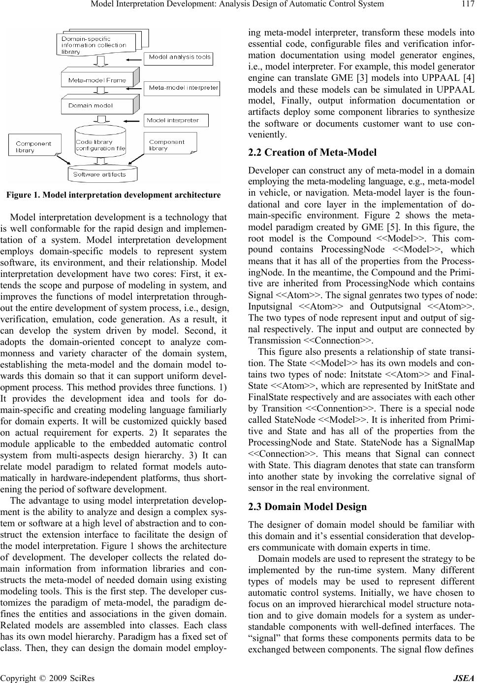
Figure 1. Model interpretation development architecture
Model interpretation development is a technology that
is well conformable for the rapid design and implemen-
tation of a system. Model interpretation development
employs domain-specific models to represent system
software, its environment, and their relationship. Model
interpretation development have two cores: First, it ex-
tends the scope and purpose of modeling in system, and
improves the functions of model interpretation through-
out the entire development of system process, i.e., design,
verification, emulation, code generation. As a result, it
can develop the system driven by model. Second, it
adopts the domain-oriented concept to analyze com-
monness and variety character of the domain system,
establishing the meta-model and the domain model to-
wards this domain so that it can support uniform devel-
opment process. This method provides three functions. 1)
It provides the development idea and tools for do-
main-specific and creating modeling language familiarly
for domain experts. It will be customized quickly based
on actual requirement for experts. 2) It separates the
module applicable to the embedded automatic control
system from multi-aspects design hierarchy. 3) It can
relate model paradigm to related format models auto-
matically in hardware-independent platforms, thus short-
ening the period of software development.
The advantage to using model interpretation develop-
ment is the ability to analyze and design a complex sys-
tem or software at a high level of abstraction and to con-
struct the extension interface to facilitate the design of
the model interpretation. Figure 1 shows the architectur e
of development. The developer collects the related do-
main information from information libraries and con-
structs the meta-model of needed domain using existing
modeling tools. This is the first step. The developer cus-
tomizes the paradigm of meta-model, the paradigm de-
fines the entities and associations in the given domain.
Related models are assembled into classes. Each class
has its own model hierarchy. Paradigm has a fixed set of
class. Then, they can design the domain model employ-
ing meta-model interpreter, transform these models into
essential code, configurable files and verification infor-
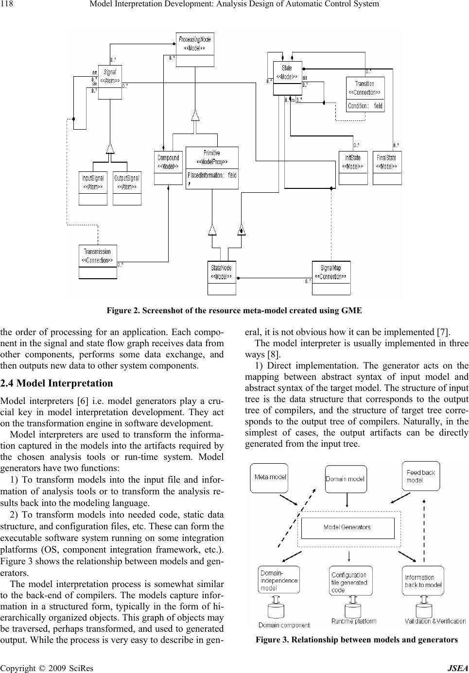
mation documentation using model generator engines,
i.e., model interpreter. For example, this model generator
engine can translate GME [3] models into UPPAAL [4]
models and these models can be simulated in UPPAAL
model, Finally, output information documentation or
artifacts deploy some component libraries to synthesize
the software or documents customer want to use con-
veniently.
2.2 Creation of Meta-Model
Developer can construct any of meta-model in a domain
employing the meta-modeling language, e.g., meta-model
in vehicle, or navigation. Meta-model layer is the foun-
dational and core layer in the implementation of do-
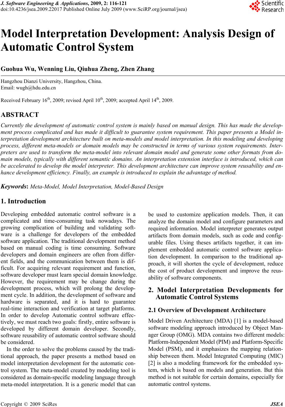
main-specific environment. Figure 2 shows the meta-
model paradigm created by GME [5]. In this figure, the
root model is the Compound <<Model>>. This com-
pound contains ProcessingNode <<Model>>, which
means that it has all of the properties from the Process-
ingNode. In the meantime, the Compound an d the Primi-
tive are inherited from ProcessingNode which contains
Signal <<Atom>>. The signal ge nrates two types of node:
Inputsignal <<Atom>> and Outputsignal <<Atom>>.
The two types of node represent input and output of sig-
nal respectively. The input and output are connected by
Transmission <<Connection>>.
This figure also presents a relationship of state transi-
tion. The State <<Model>> has its own mode ls and con-
tains two types of node: Initstate <<Atom>> and Final-
State <<Atom>>, which are represented by InitState and
FinalState respectively and are associates with each other
by Transition <<Connention>>. There is a special node
called StateNode <<Model>>. It is inherited from Primi-
tive and State and has all of the properties from the
ProcessingNode and State. StateNode has a SignalMap
<<Connection>>. This means that Signal can connect
with State. This diagram denotes that state can transform
into another state by invoking the correlative signal of
sensor in the real environment.
2.3 Domain Model Design
The designer of domain model should be familiar with
this domain and it’s essential consideration that develop-
ers communicate with domain experts in time.
Domain models are used to represent the strategy to be
implemented by the run-time system. Many different
types of models may be used to represent different
automatic control systems. Initially, we have chosen to
focus on an improved hierarchical model structure nota-
tion and to give domain models for a system as under-
standable components with well-defined interfaces. The
“signal” that forms these components permits data to be
exchanged between components. The signal flow defines
Copyright © 2009 SciRes JSEA