M.-S. Liang et al.
counter electrode preparation, and cell assembly.
The three dyes, N719, N749 and N3, are purchased from Dyesol. The dyes are in powder form, and are diluted
with ethanol or acetonitrile/tert-butanol (1:1 vol:vol).
The conductive side of the FTO glass can be identified with a multi-meter. Marking was made on the non-
conductive side using an engraving pen. The FTO glasses are then cut into 2 cm × 2 cm size by using diamond
cutter. The glass pieces were washed by using detergent, rinsed with distilled water, de-ionized water, acetone,
and ethanol and deionised water again in order to remove all contaminants.
TiO2 nanoparticles are synthesized using the acid-digestion vessels. TiO2 paste was applied on the FTO con-
ductive surface by doctor blade techniques. Scotch tape is used to define a one centimetre square area on a
cleaned microscope slide. A thin film of TiO2 paste is applied onto the glass plate with a glass rod. The TiO2 thin
film left in the ambient for relaxation to reduce surface irregularity. The electrode is then sintered on a hot plate
at 125˚C for 6 minutes. The steps above are repeated until the desired thickness is achieved. Normally one or
two layers of TiO2 paste A and paste B is enough to get the optimum thickness for high efficiency DSSC. This is
followed by another layer of light-scattering TiO2 films containing 400 nm sized anatase particles of 2 - 5 µm.
The electrodes coated with the TiO2 pastes were gradually heated under an air flow at 325˚C for 5 minutes, sub-
sequently at 375˚C for 5 minutes, followed by 450˚C for 15 minutes and finally at 500˚C for 15 minutes [5]. The
electrode is then slow cooled at ambient to around 80˚C. The paste is then shaped into 0.5 cm × 0.5 cm by using
a blade and the side is cleaned with ethanol solution to remove the residues. The photo-electrode is then soaked
into dye solution for the next 24 hours.
Platinum counter electrode is prepared by drilling a small hole onto a piece of FTO glass. Platinum paste is
then applied onto the FTO glass by doctor blade method. The paste is heated at 400˚C for 15 minutes on a hot-
plate.
Thermosetting sealant is cut into the size required to seal the electrolyte onto the cell assembly. Attentions
have to be taken so that the sealant is not too large which could not seal the glasses properly; or too small that
will cover up the drilled hole on the Pt counter electrode. The photo-electrode and Pt counter electrode are as-
sembled by melting the sealant at a temperature around 125˚C to 145˚C.
Finally, the electrolyte is added through the hole in the back of the counter electrode. A small piece of sealant
is used to cover the drilled hole so that the electrolyte is not evaporated from the cell.
Table 1 shows four different configurations of paste with different article sizes and layer thickness.
2.2. Measurements
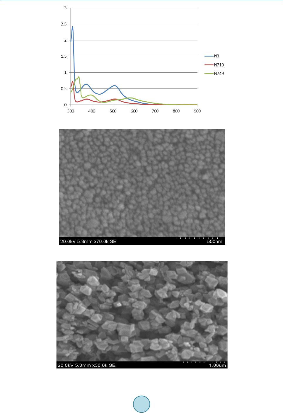
The characteristics of the TiO2 film may affect the dye adsorption and consequently influence the performance
of the solar cell. Scanning electron microscopy (SEM) and electron diffraction X-ray (EDX) analysis were used
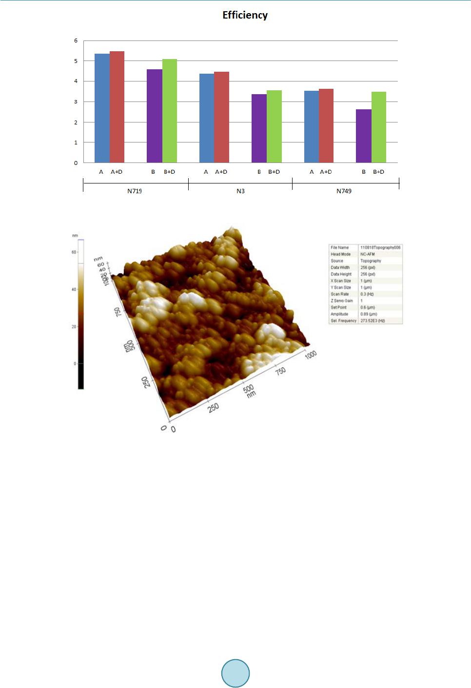
to investigate the morphologies, particle and pore sizes and weight ratios of elements for the TiO2 films. X-ray
diffraction (XRD) techniques were employed to investigate the influence of thickness on the crystallinity of the
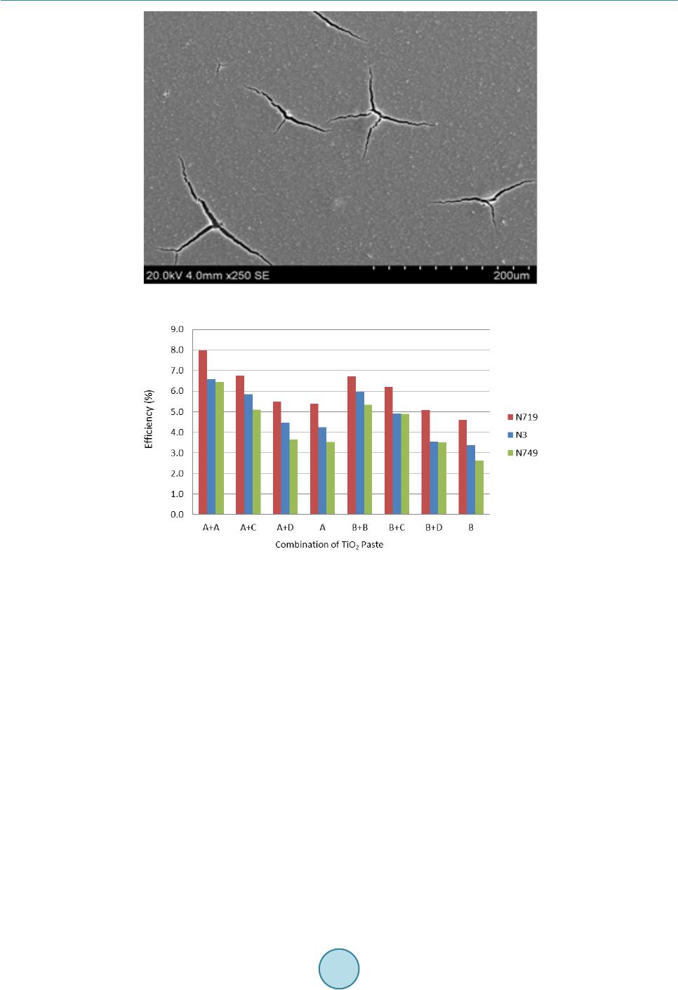
TiO2 film. UV-visible spectrometry was utilised to investigate dye loading. An I-V test was used to determine
the cell parameters, such as: short circuit current density, Jsc, open circuit voltage, Voc, maximum power, Pmax
and conversion efficiency, η of the DSSCs.
3. Results and Discussion
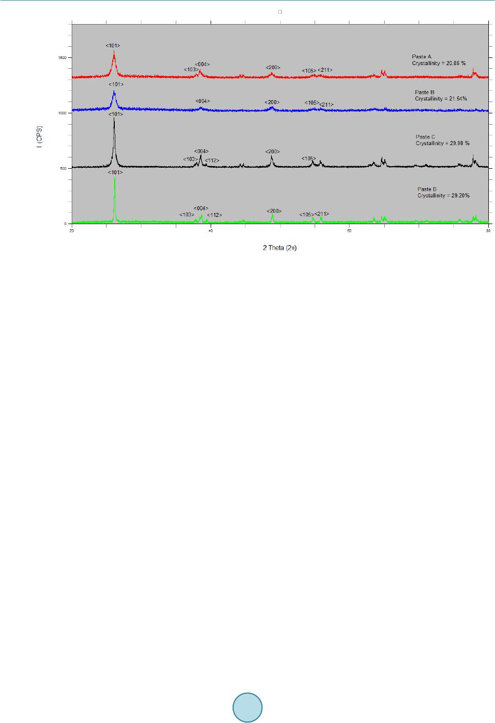
3.1. XRD
Figure 1 shows the XRD patterns for Paste A, B, C and D respectively. All the results show a unique pattern,
however they have similarities in the peak at around 26˚, 38˚, 48˚, 54˚ and 55˚. Paste A has the crystallinity of
Table 1. Particle sizes of the various samples.
Paste Average Particle Sizes (n m) Sintered Layer (µm) Type of Layer
A 20 6 - 7 Active
B 20 3 Active
C 350 - 450 7 - 8 Active
D 150 - 250 3 Scattering Layer