Paper Menu >>
Journal Menu >>
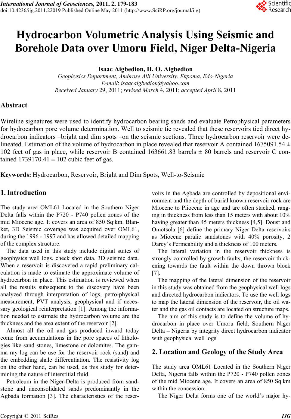 International Journal of Geosciences, 2011, 2, 179-183 doi:10.4236/ijg.2011.22019 Published Online May 2011 (http://www.SciRP.org/journal/ijg) Copyright © 2011 SciRes. IJG Hydrocarbon Volumetric Analysis Using Seismic and Borehole Data over Umoru Field, Niger Delta-Nigeria Isaac Aigbedion, H. O. Aigbedion Geophysics Department, Ambrose Alli University, Ekpoma, Edo-Nigeria E-mail: isaacaigbedion@yahoo.co m Received January 29, 2011; revised March 4, 2011; accepted April 8, 2011 Abstract Wireline signatures were used to identify hydrocarbon bearing sands and evaluate Petrophysical parameters for hydrocarbon pore volume determination. Well to seismic tie revealed that these reservoirs tied direct hy- drocarbon indicators –bright and dim spots –on the seismic sections. Three hydrocarbon reservoir were de- lineated. Estimation of the volume of hydrocarbon in place revealed that reservoir A contained 1675091.54 ± 102 feet of gas in place, while reservoir B contained 163661.83 barrels ± 80 barrels and reservoir C con- tained 1739170.41 ± 102 cubic feet of gas. Keywords: Hydrocarbon, Reservoir, Bright and Dim Spots, Well-to-Seismic 1. Introduction The study area OML61 Located in the Southern Niger Delta falls within the P720 - P740 pollen zones of the mid Miocene age. It covers an area of 850 Sq·km. Blan- ket, 3D Seismic coverage was acquired over OML61, during the 1996 - 1997 and has allowed detailed mapping of the complex structure. The data used in this study include digital suites of geophysics well logs, check shot data, 3D seismic data. When a reservoir is discovered a rapid preliminary cal- culation is made to estimate the approximate volume of hydrocarbon in place. This estimation is reviewed when all the results subsequent to the discovery have been analyzed through interpretation of logs, petro-physical measurement, PVT analysis, geophysical and if neces- sary geological reinterpretation [1]. Among the informa- tion needed to estimate the hydrocarbon volume are the thickness and the area extent of the reservoir [2]. Almost all the oil and gas produced inward today come from accumulations in the pore spaces of litholo- gies like sand stones, limestone or dolomites. The gam- ma ray log can be use for the reservoir rock (sand) and the embedding shale differentiation. The resistivity log on the other hand, can be used, as this study for deter- mining the nature of interstitial fluid. Petroleum in the Niger-Delta is produced from sand- stone and unconsolidated sands predominantly in the Agbada formation [3]. The characteristics of the reser- voirs in the Agbada are controlled by depositional envi- ronment and the depth of burial known reservoir rock are Miocene to Pliocene in age and are often stacked, rang- ing in thickness from less than 15 meters with about 10% having greater than 45 meters thickness [4,5]. Doust and Omotsola [6] define the primary Niger Delta reservoirs as Miocene paralic sandstones with 40% porosity, 2 Darcy’s Permeability and a thickness of 100 meters. The lateral variation in the reservoir thickness is strongly controlled by growth faults, the reservoir thick- ening towards the fault within the down thrown block [7]. The mapping of the lateral dimension of the reservoir in this study was obtained from the geophysical well logs and directed hydrocarbon indicators. To use the well logs to map the lateral dimension of the reservoir, the oil wa- ter and the gas oil contacts are located on structure maps. The aim of this study is to define the volume of hy- drocarbon in place over Umoru field, Southern Niger Delta – Nigeria by integrity direct hydrocarbon indicator with geophysical well logs. 2. Location and Geology of the Study Area The study area OML61 Located in the Southern Niger Delta, Nigeria falls within the P720 - P740 pollen zones of the mid Miocene age. It covers an area of 850 Sq·km within the concession. The Niger Delta forms one of the world’s major hy- 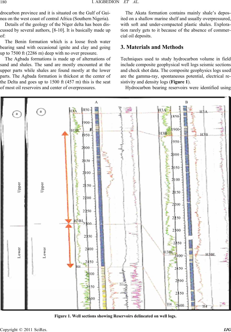 I. AIGBEDION ET AL. 180 drocarbon province and it is situated on the Gulf of Gui- nea on the west coast of central Africa (Southern Nigeria). Details of the geology of the Niger delta has been dis- cussed by several authors, [8-10]. It is basically made up of: The Benin formation which is a loose fresh water bearing sand with occasional ignite and clay and going up to 7500 ft (2286 m) deep with no over pressure. The Agbada formations is made up of alternations of sand and shales. The sand are mostly encounted at the upper parts while shales are found mostly at the lower parts. The Agbada formation is thickest at the center of the Delta and goes up to 1500 ft (457 m) this is the seat of most oil reservoirs and center of overpressures. The Akata formation contains mainly shale’s depos- ited on a shallow marine shelf and usually overpressured, with soft and under-compacted plastic shales. Explora- tion rarely gets to it because of the absence of commer- cial oil deposits. 3. Materials and Methods Techniques used to study hydrocarbon volume in field include composite geophysical well logs seismic sections and check shot data. The composite geophysics logs used are the gamma-ray, spontaneous potential, electrical re- sistivity and density logs (Figure 1). Hydrocarbon bearing reservoirs were identified using Figure 1. Well sections showing Reservoirs delineated on well logs. Copyright © 2011 SciRes. IJG  I. AIGBEDION ET AL. Copyright © 2011 SciRes. IJG 181 the gamma ray log and the electrical resistivity log. Res- ervoir Petrophysical analysis was carried using the geo- physical log signatures to compute for the water satura- tion/hydrocarbon saturation porosity, reservoir thick- ness (net and gross). The reservoir hydrocarbon was computed using [4] 1 vj w H cKv S where Sw = average water saturation Ф = Average effective porosity Vj = net production sand value K depends on the nature of fluid present which is giv- en as the product of the area and thickness (A × L) The general form of the error equation for the com- puted hydrocarbon volume in place is 2 vw vw H c Lh S H cLh S 2w vv w S Lh Hc HcLh S where Δ represent error. The well-to-seismic tie of the hydrocarbon reservoirs was obtained from the check shot data and displayed on the seismic lines they intersected. The hydrocarbon boundaries were mapped using direct indicators from 3-D seismic. The square grid method was used to deter- mined the area extent of the reservoir. 4. Results Hydrocarbon bearing reservoirs were formed to be asso- ciated with direct hydrocarbon indicators on seismic sec- tions through the well-to-seismic tie. Since the bright and dim spots are indicated of hydrocarbon presence, the lateral boundaries of these reservoirs were mapped from the amplitudes .The total estimated area covered by the gas and was 9.77 km2 reservoir A. The same analysis was performed for reservoirs B and C that is, reflec- tion amplitude maps were generated from horizon two and three respectively and the zone of anomalous high amplitude were used to map the boundaries of the res- ervoir (they matched bright spots on seismic sections). The reservoir area extent estimation from the square grid method revealed that reservoir B covered an area of 10.57 km2 while reservoir C covered an area extent of 12.00 km2. 5. Results and Discussion Hydrocarbon bearing reservoirs were found to be associ- ated with direct hydrocarbon indicators on seismic sec- tions through the well-to-seismic tie (Figures 1 and 2). The reservoir Petrophysical parameters obtained from the three hydrocarbon bearing reservoir A, B and C are shown in Tables 1, 2, and 3. The hydrocarbon saturation and effective porosity estimated in reservoir A varied from 0.82 to 0.87 and 0.35 to 0.36 respectively. The net thickness of the reservoir was found to be 50 ft (15 m). In reservoir B, hydrocarbon saturation varied between 0.82 and 0.83, while effective porosity varied between 0.28 and 0.30. The net thickness of the reservoir varied between 22 ft (6.7 m) and 33 ft (10 m). In reservoir C, hydrocarbon saturation varied between 0.72 and 0.70, while effective porosity varied between 0.28 and l0.30. The net thickness of the reservoir varied between Table 1. Petrophysical parameters from reservoir A. Well Top (Md) ft (m) Bottom (md) ft (m) Thickness Gross ft (m) Thickness net ft (m) True Resistivity Porosity effective (Ф)Fluid type Water saturation Hydrocarb on saturation Umoru 01 5150(1570) 5200(1585) 50(15) 50(15) 100 0.35 Gas 0.13 0.87 Umoru 02 5120(1570) 5200(1576) 50(15) 50(15) 110 0.36 Gas 0.18 0.82 Table 2. Petrophysical analysis from reservoir B. Well Top (md) Bottom ft (m) Thickness (cross) ft (m) Thickness Net f(t) (m) True Resistivity ohm-m Porosity Effective Fluid type Water Saturation Hydrocarbon Saturation Umoru 01 5355(1632) 5380(1640) 25(7.6) 22(6.7) 150 0.30 Oil 0.18 0.82 Umoru 02 5345(1629) 5379(1640) 34(10.4) 33(10.0) 120 0.28 Oil 0.67 0.83 Table 3. Reservoir C. Umoru 01 7410(2259) 7470(2277) 60(18.3) 56(17.1) 100 0.26 Gas 0.28 0.72 Umoru 02 7400(2250) 7490(2283) 90(27.4) 89(27.3) 110 0.25 Gas 0.30 0.70  I. AIGBEDION ET AL. 182 Table 4. Volume estimate in reservoirs A, B and C. Reservoir Thickness ft (m) Area (m2) Porosity Hydrocarbon saturation Hydrocarbon in place A 50(15.24) 10120 0.36 0.85 1675091.54 cubic feet of gas B 27.5(8.38) 12900 0.29 0.83 163661.83 barrels C 72(21.94) 11453 0.26 0.75 1739170.41 cubic feet of gas Figure 2. Well to seismic section tie of reservoir showing dim spots. 56 ft (17.1 m) and 89 ft (27.3 m) and 89 ft (27.3 m). The top of reservoir A tied to a dim spot at the two way travel time of 2513 ms ie depth of 6776 ft (2965.34 m). Similarly top of reservoir B and C tied dim spots on the Copyright © 2011 SciRes. IJG  I. AIGBEDION ET AL.183 seismic sections. 6. Conclusions The integration of well and seismic data provides insight to reservoir hydrocarbon volume which may be utilized in exploration evaluations and in well bore planning. From the well log interpretation, three hydrocarbon pro- ducing reservoirs (A, B and C) were identified. Well-to- seismic tie revealed that hydrocarbon bearing reservoirs were associated with directed hydrocarbon indicators (Bright and dim spots) on the seismic sections. The anti- clinial structure of the centre of the field was found to be principal structure responsible for hydrocarbon entrap- ment. Estimation of the volume of hydrocarbon in place re- vealed that reservoir A contained an estimate of 1675 091.54 ± 102 cubic feet of gas, while reservoir B con- tained 163 661.83 barrels ± 80 barrels and reservoir C contained 1739 170.41 ± 102 cubic feet of gas. 7. References [1] I. Aigbedion, M. O. Ehigiator and R. Ehigiator, “Charac- terization of Reservoir Using Petrophysical and Core Da- ta,” Geophysical Journal Russia, Vol. 19, 2010, pp. 71- 75. [2] M. Edward, “Evaluation of Petrophysical Properties of Reservoir Rocks Using Well Log Analysis,” Ph.D. Thesis, Jordan, 1988. [3] Schlumberger, “Log Interpretation Principles and Appli- cation,” Schlumberger Education Service, Houston, 1989, pp. 50-59. [4] I. Aigbedion, “Petrophysical Analysis of Two Onshore Wells in the Niger-Delta Nigeria,” Journal of Science and Technology, Vol. 4, 2004, pp. 56-59. [5] S. J. Kulke, “Niger Delta Geology,” Journal of Petroleum, Vol. 24, 1995, pp. 30-35. [6] H. Doust and E. Omatsola, “Geology of Niger-Delta Ni- geria,” America Association of Petroleum Geologist, 1990, pp. 239-247. [7] A. R. Brown, “Interpretation of Seismic Data,” Memoir 42 SEG Investigation in Geophysics, American Associa- tion of Petroleum Geologists, 2005, pp. 12-89. [8] Schlumberger, “Basic Log Interpretation Seminar,” Sch- lumberger Education Service, Houston, 1984, pp. 1-5. [9] P. J. Merki, “Structural Geology of the Cenozoic Niger Delta,” Journal of Geology, Vol. 4, 1970, pp. 34-36. [10] K. C. Short and A. J. Stauble, “Outline of the Geology of Niger Delta,” AAPG Journal, Vol. 5, 1967, pp. 761-764. Copyright © 2011 SciRes. IJG |