Paper Menu >>
Journal Menu >>
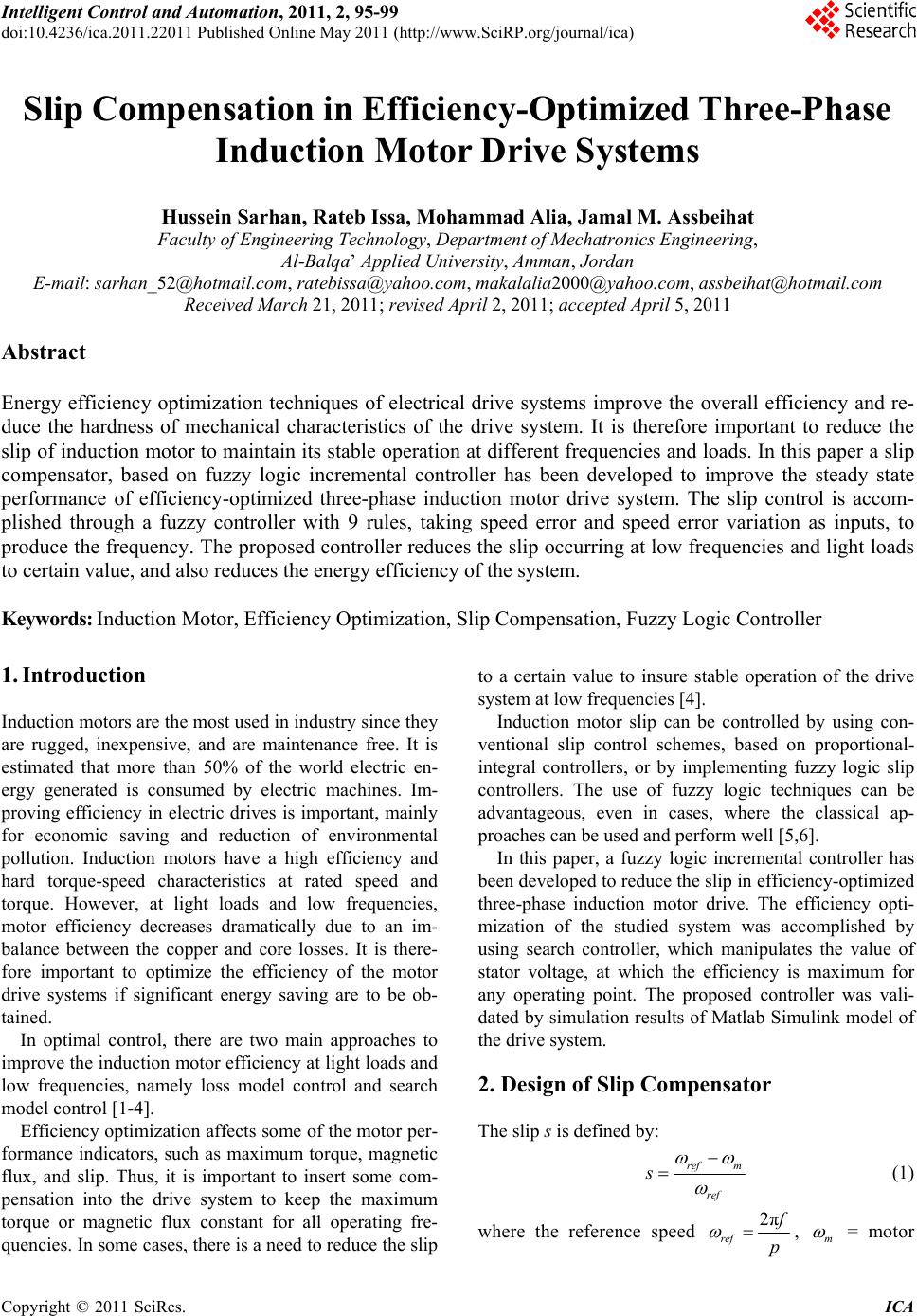 Intelligent Control and Automation, 2011, 2, 95-99 doi:10.4236/ica.2011.22011 Published Online May 2011 (http://www.SciRP.org/journal/ica) Copyright © 2011 SciRes. ICA Slip Compensation in Efficiency-Optimized Three-Phase Induction Motor Drive Systems Hussein Sarhan, Rateb Issa, Mohammad Alia, Jamal M. Assbeihat Faculty of Engineering Technology, Department of Mec hatronics En g i neering, Al-Balqa’ Applied University, Amman, Jordan E-mail: sarhan_52@hotmail.com, ratebissa@yaho o.com, makalalia2000@ y ahoo.com, assbeihat@hotmail.com Received March 21, 2011; revised April 2, 2011; accepted April 5, 2011 Abstract Energy efficiency optimization techniques of electrical drive systems improve the overall efficiency and re- duce the hardness of mechanical characteristics of the drive system. It is therefore important to reduce the slip of induction motor to maintain its stable operation at different frequencies and loads. In this paper a slip compensator, based on fuzzy logic incremental controller has been developed to improve the steady state performance of efficiency-optimized three-phase induction motor drive system. The slip control is accom- plished through a fuzzy controller with 9 rules, taking speed error and speed error variation as inputs, to produce the frequency. The proposed controller reduces the slip occurring at low frequencies and light loads to certain value, and also reduces the energy efficiency of the system. Keywords: Induction Motor, Efficiency Optimization, Slip Compensation, Fuzzy Logic Controller 1. Introduction Induction motors are the most used in industry since they are rugged, inexpensive, and are maintenance free. It is estimated that more than 50% of the world electric en- ergy generated is consumed by electric machines. Im- proving efficiency in electric drives is important, mainly for economic saving and reduction of environmental pollution. Induction motors have a high efficiency and hard torque-speed characteristics at rated speed and torque. However, at light loads and low frequencies, motor efficiency decreases dramatically due to an im- balance between the copper and core losses. It is there- fore important to optimize the efficiency of the motor drive systems if significant energy saving are to be ob- tained. In optimal control, there are two main approaches to improve the induction motor efficiency at light loads and low frequencies, namely loss model control and search model control [1-4]. Efficiency optimization affects some of the motor per- formance indicators, such as maximum torque, magnetic flux, and slip. Thus, it is important to insert some com- pensation into the drive system to keep the maximum torque or magnetic flux constant for all operating fre- quencies. In some cases, there is a need to reduce the slip to a certain value to insure stable operation of the drive system at low frequencies [4]. Induction motor slip can be controlled by using con- ventional slip control schemes, based on proportional- integral controllers, or by implementing fuzzy logic slip controllers. The use of fuzzy logic techniques can be advantageous, even in cases, where the classical ap- proaches can be used and perform well [5,6]. In this paper, a fuzzy logic incremental controller has been developed to reduce the slip in efficiency-optimized three-phase induction motor drive. The efficiency opti- mization of the studied system was accomplished by using search controller, which manipulates the value of stator voltage, at which the efficiency is maximum for any operating point. The proposed controller was vali- dated by simulation results of Matlab Simulink model of the drive system. 2. Design of Slip Compensator The slip s is defined by: ref m ref s (1) where the reference speed 2π ref f p , m = motor 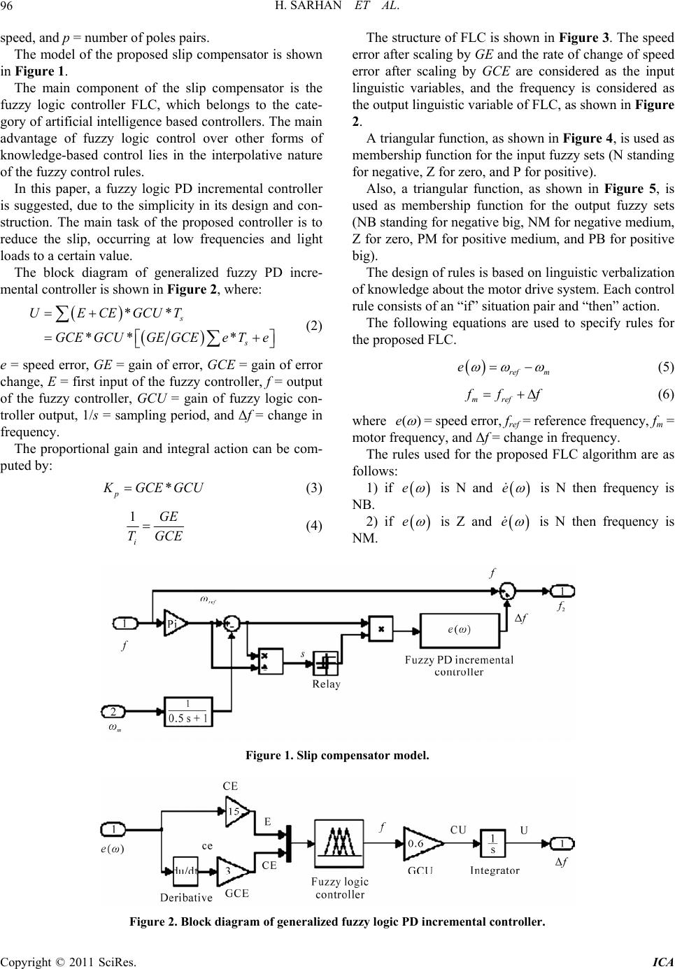 H. SARHAN ET AL. 96 speed, and p = number of poles pairs. The model of the proposed slip compensator is shown in Figure 1. The main component of the slip compensator is the fuzzy logic controller FLC, which belongs to the cate- gory of artificial intelligence based controllers. The main advantage of fuzzy logic control over other forms of knowledge-based control lies in the interpolative nature of the fuzzy control rules. In this paper, a fuzzy logic PD incremental controller is suggested, due to the simplicity in its design and con- struction. The main task of the proposed controller is to reduce the slip, occurring at low frequencies and light loads to a certain value. The block diagram of generalized fuzzy PD incre- mental controller is shown in Figure 2, where: ** ** * s s UECEGCUT GCEGCUGE GCEeTe (2) e = speed error, GE = gain of error, GCE = gain of error change, E = first input of the fuzzy controller, f = output of the fuzzy controller, GCU = gain of fuzzy logic con- troller output, 1/s = sampling period, and Δf = change in frequency. The proportional gain and integral action can be com- puted by: * p K GCE GCU (3) 1 i GE TGCE (4) The structure of FLC is shown in Figure 3. The speed error after scaling by GE and the rate of change of speed error after scaling by GCE are considered as the input linguistic variables, and the frequency is considered as the output linguistic variable of FLC, as shown in Figure 2. A triangular function, as shown in Figure 4, is used as membership function for the input fuzzy sets (N standing for negative, Z for zero, and P for positive). Also, a triangular function, as shown in Figure 5, is used as membership function for the output fuzzy sets (NB standing for negative big, NM for negative medium, Z for zero, PM for positive medium, and PB for positive big). The design of rules is based on linguistic verbalization of knowledge about the motor drive system. Each control rule consists of an “if” situation pair and “then” action. The following equations are used to specify rules for the proposed FLC. ref m e (5) mref f ff (6) where ()e = speed error, fref = reference frequency, fm = motor frequency, and Δf = change in frequency. The rules used for the proposed FLC algorithm are as follows: 1) if e is N and e is N then frequency is NB. 2) if e is Z and e is N then frequency is NM. Figure 1. Slip compensator model. Figure 2. Block diagram of generalized fuzzy logic PD incremental controller. Copyright © 2011 SciRes. ICA 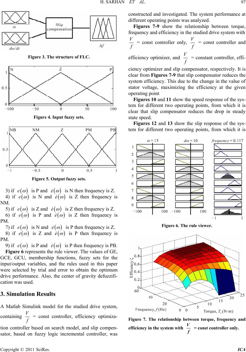 H. SARHAN ET AL.97 Figure 3. The structure of FLC. Figure 4. Input fuzzy sets. Figure 5. Output fuzzy sets. 3) if e is P and e is N then frequency is Z. ) if4 e is N and e is Z then frequency is NM. 5) if e is Z and e is Z then frequency is Z. 6) if e is P and e is Z then frequency is PM. 7) if e is N and e is P then frequency is Z. 8) if e is Z and e is P then frequency is PM. 9) if e is P and e is P then frequency is PB. Fig he rule upresents tviewer. The values of GE, GCE, GCU, p fu in Results or the studied drive system, re 6 re membershi nctions, fuzzy sets for the put/output variables, and the rules used in this paper were selected by trial and error to obtain the optimum drive performance. Also, the center of gravity defuzzifi- cation was used. 3. Simulation A Matlab Simulink model f containing V f = const controller, efficiency optimiza- tion control based on search model, and slip compen-ler sator, based on fuzzy logic incremental controller, was constructed and investigated. The system performance at different operating points was analyzed. Figures 7-9 show the relationship between torque, frequency and efficiency in the studied drive system with V f = const controller only, V f = const controller and efficiency optimizer, and V f = constant controller, effi- cie pe clear from Figures 7-9 that slip compensator reduces the e t stator voltage, maximizing the efficiency at the given ncy optimizer and slip comnsator, respectively. It is system efficiency. This duo the change in the value of operating point Figures 10 and 11 show the speed response of the sys- tem for different two operating points, from which it is clear that slip compensator reduces the drop in steady state speed. Figures 12 and 13 show the slip response of the sys- tem for different two operating points, from which it is Figure 6. The rule viewer. Figure 7. The relationship between torque, frequency and efficiency in the system with V f = const controller only. Copyright © 2011 SciRes. ICA  H. SARHAN ET AL. 98 Figure 8. The relationship between torque, frequency and efficiency in the system with V f = const controller and efficiency optimizer. Figure 9. The relationship between torque, frequency and efficiency in the system with V f = const controller, effi- ciency optimizer and slip compensator. Figure 11. Speed response at load torque = 15 N·m and frequency = 5 Hz. Figure 12. Slip response at load torque = 5 N·m and fre- quency = 5 Hz. Figure 10. Speed response at load torque = 5 N·m and fre- quency = 5 Hz. Figure 13. Slip response at load torque = 15 N·m and fre- quency = 20 Hz. Copyright © 2011 SciRes. ICA 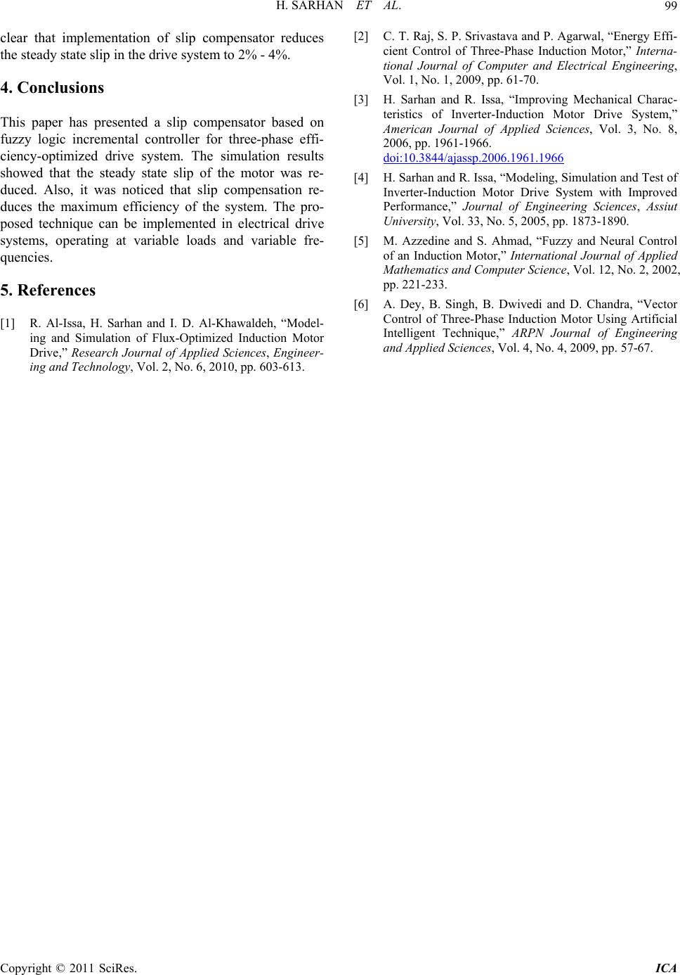 H. SARHAN ET AL. Copyright © 2011 SciRes. ICA 99 clear that implementation of slip compensator reduces the steady state slip in the drive system to 2% - 4%. 4. Conclusions This paper has presented a slip compensator based fuzzy logic incremental controller for three-phase effi- ciency-optimized drive system. The simulation results showed that the steady state slip of the motor was re- duced. Also, it was noticed that slip compensation re- duces the maximum efficiency of the system. The pro- posed technique can be implemented in electrical drive systems, operating at variable loads and variable f quencies. neer- ogy, Vol. 2, No. 6, 2010, pp. 603-613. Control of Three-Phase Induction Motor,” Journal of Computer and Electrical Engineering, 009, pp. 61-70. R. Issa, “Improving Mechanical Charac- on teristics of Inverter-Induction Motor Drive System,” American Journal of Applied Sciences, Vol. 3, No. 8, 2006, pp. 1961-1966. re- 5. References [1] R. Al-Issa, H. Sarhan and I. D. Al-Khawaldeh, “Model- ing and Simulation of Flux-Optimized Induction Motor Drive,” Research Journal of Applied Sciences, Engi ing and Technol [2] C. T. Raj, S. P. Srivastava and P. Agarwal, “Energy Effi- cient Interna- tional Vol. 1, No. 1, 2 ] H. Sarhan and[3 doi:10.3844/ajassp.2006.1961.1966 [4] H. Sarhan and R. Issa, “Modeling, Simulation and Test of Inverter-Induction Motor Drive System with Improved Performance,” Journal of Engineering Sciences, Assiut University, Vol. 33, No. 5, 2005, pp. 1873-1890. [5] M. Azzedine and S. Ahmad, “Fuzzy and Neural Control of an Induction Motor,” International Journal of Applied Mathematics and Computer Science, Vol. 12, No. 2, 2002, pp. 221-233. [6] A. Dey, B. Singh, B. Dwivedi and D. Chandra, “Vector Control of Three-Phase Induction Motor Using Artificial Intelligent Technique,” ARPN Journal of Engineering and Applied Sciences, Vol. 4, No. 4, 2009, pp. 57-67. |