 Journal of Applied Mathematics and Physics, 2014, 2, 1031-1038 Published Online November 2014 in SciRes. http://www.scirp.org/journal/jamp http://dx.doi.org/10.4236/jamp.2014.212117 How to cite this paper: Yu, C.J., Kim, D. and Zhao, Y. (2014) Lift and Thrust Characteristics of Flapping Wing Aerial Vehicle with Pitching and Flapping Motion. Journal of Applied Mathematics and Physics, 2, 1031-1038. http://dx.doi.org/10.4236/jamp.2014.212117 Lift and Thrust Characteristics of Flapping Wing Aerial Vehicle with Pitching and Flapping Motion Chunjin Yu1,2, Daewon Kim2, Yi Zhao2 1Institute of Flight Vehicle Engineering, Nanchang Hangkong University, Nanchang, China 2Department of Aerospace Engineering, Embry-Riddle Aeronautical University, Daytona Beach, USA Email: 415765032@qq.com Received August 2014 Abstract Development of flapping wing aerial vehicle (FWAV) has been of interest in the aerospace commu- nity with ongoing research into unsteady and low Reynolds number aerodynamics based on the vortex lattice method. Most of the previous research has been about pitching and plunging motion of the FWAV. With pitching and flapping motion of FMAV, people usually study it by experiment, and little work has been done by numerical calculation. In this paper, three-d imension unsteady vortex lattice method is applied to study the lift and thrust of FWAV with pitching and flapping motion. The results show that: 1) Lift is mainly produced during down stroke, however, thrust is produced during both down stroke and upstroke. The lift and thrust produced during down stroke are much more than that produced during upstroke. 2) Lift and thrust increase with the increase of flapping freque ncy; 3) Thrust increases with the increase of flapping amplitude, but the lift decreases with the increase of flapping amplitude; 4) Lift and thrust increase with the increase of mean pitching an- gle, but the effect on lift is much more than on thrust. This research is helpful to understand the flight mechanism of birds, thus improving the design of FWAV simulating birds. Keywords Flapping Wing, Aerial Vehicle, Lift Ch aracteri stics, Thrust Charac te ris tics 1. Introduction All flying animals in the nature use flapping-wing flight mode. For more than a decade, flapping wing aerial ve- hicle (FWAV) inspired by biological flyers such as insects and birds are suitable for missions involving con- fined spaces, such as buildings or short distances. Therefore, studying flapping-wing aerial vehicles have a wide application foreground. Recent studies have uncovered previously unknown unsteady aerodynamic mechanisms of flapping flight. These include the clap and fling [1], leading edge vortex generation [2], rotational lift [3], and wing-wing inte- raction [4] mechanisms, which help explain the basic principles of unsteady force generation in flight. The aerodynamics of insect wings is entirely different from the conventional wings. However Kesel [5] showed that 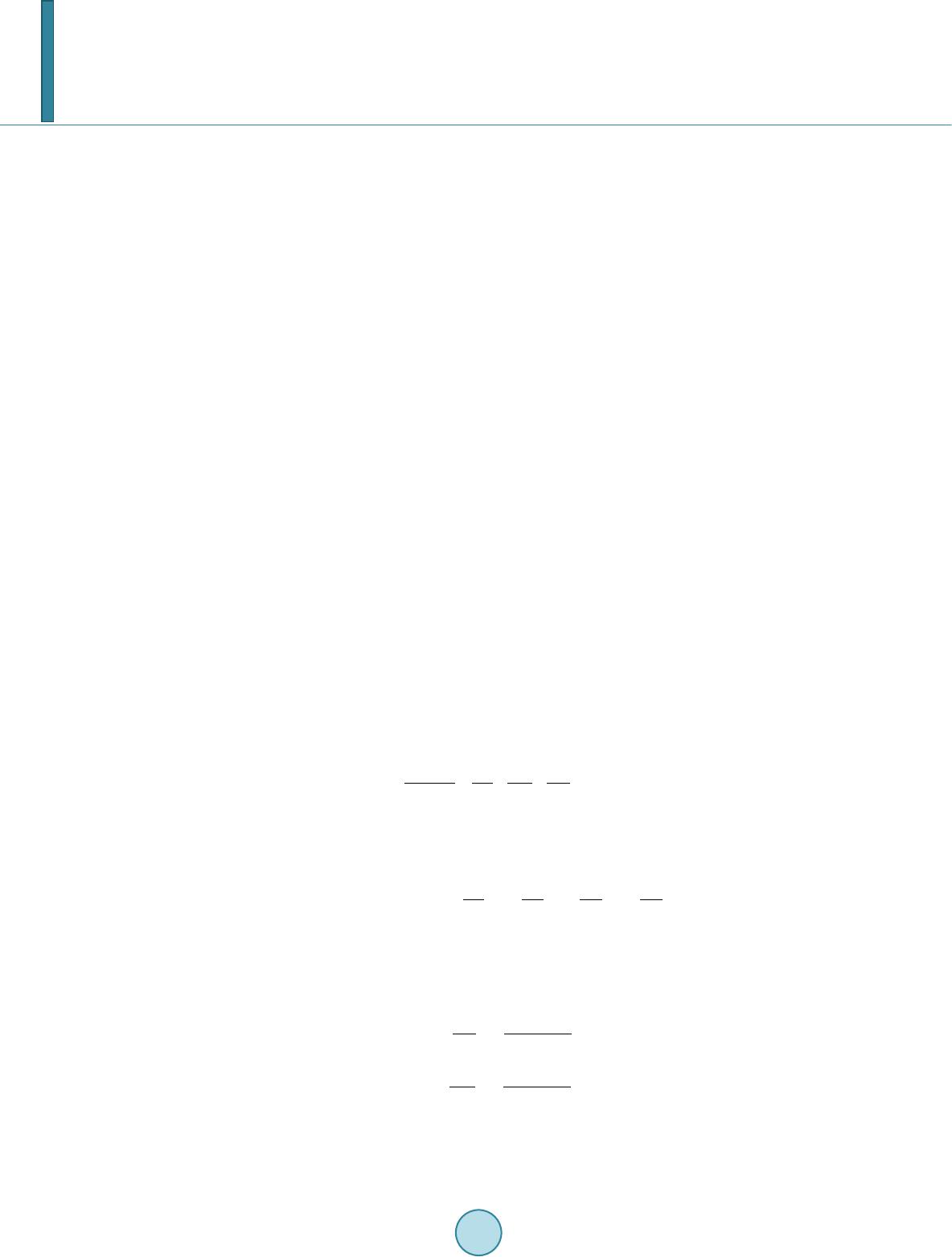 C. J. Yu et al. the wings of dragonfly is comparable wing conventional profiles in a steady flow, but unlike conventional pro- files negative pressure occurs on both the upper and lower surfaces of the wing at angles of attack from −100 to 00. Reduced frequency increases with increase in unsteady effects and for an insect it will be greater than 0.75. But in the case of birds [6] they are very low and crudely give their forward velocity, it is most often described by the vortex wing theory [7]. Most researchers studied a combined pitching and plunging motion of FW AV , such as Jones [8], Heath cote [9], Stewart [10], and so on. Their analysis was based on two-dimension aerodynamic model. To research the pitching and flapping motion of flapping wing, since the complexity of airflow, people adopted three-dimension aerodynamic model to calculate the aerodynamic performance of flapping wing. Smith [11] used an unsteady aerodynamic panel method to simulate a tethered moth’s flapping wings, Fitzgerald et al. [12] stu- died the fluid-structure interaction of flexible flapping wing systems by unsteady vortex lattice method (UVLM), and found that UVLM is suitable to calculate the unsteady aerodynamic force. Yu et al. [13] derived a formula to calculate the aerodynamic force based on three dimension unsteady vortex lattice method and vector analysis. Some researchers carried out experimental investigation on aerodynamic performance of FWAV. Mazaheri et al. [14] designed a flapping-wing system and an experimental set-up to measure the unsteady aerodynamic forces of the flapping wing motion. Muniappan et al. [15] discussed the effect of aspect ratio and the wing plan- for m shape on lift and thrust force e xpe rime ntal l y. Most work mentioned above were either on the numerical analysis or on the experimental investigation. In this paper, both numerical analysis and experimental investigatio n will be used to analyze the lift and thrust characteristics of FWAV with pitching and flapping motion. As an example, birds will be used to explain these reasons. This research is helpful to improve the design of FWAV. 2. Aerodynamics—Unsteady Vortex Lattice Method Thr ee -dimension unsteady vortex lattice method (UVLM) is used to calculate the aerodynamics in this paper. The diagrammatic drawing of UVLM is shown as Figure 1 by discretizing the continuous sheet on a wing into a set of ring vortices of unknown magnitude. The rings are made of four finite line segments of equal vorticity magnitude. The Kutta condition is composed on the trailing edge of the wing and no-penetration boundary con- dition is imposed at a set of control points. At each time step in the analysis the voracity along the trailing edge is shed into the wake. The finite segments of bound vorticity and wake vorticity induce a downwash on the wing according to the Biot-Savart law. The Biot-Savart law is then put into matrix form to find the total downwash at each control point from all of the bound ring vortices and wake vortices. The pressures and loads can be calculated by using the unsteady Bernoulli equation: 2 2 22 ref ref f Pp Q t ν ρ −∂Φ =−+ ∂ (1) whe r e Pref is reference pressure, p is pressure of fluid, ρf is fluid density, Q is fluid velocity, νref is reference ve- locity, Φ is the potential of flow, t is the time. The pressure difference between the flapping-wing upper and lower surfaces is then 22 22 tt lu ul ul QQ PPP tt ρ ∂Φ ∂Φ ∆= −=−+− ∂∂ (2) whe r e is the pressure of lower surfaces, is the pressure of upper surfaces. The tangential velocity due to the wing vortices will have two components on the wing, and it can be ap- proximated by the two directions, , , on the surface. The velocity of direction due to wing vortices on each element is 1, 2 iji j i ij c τ − Γ −Γ ∂Φ ±=± ∂∆ (3a ) ,1 2 iji j j ij b τ − Γ −Γ ∂Φ ±=± ∂∆ (3b) where “ ” represents the upper and lower surfaces, respectively; and are the panel lengths in the i-th and j-th directions. Similarly, and are the panel tangential vectors in the and directions, 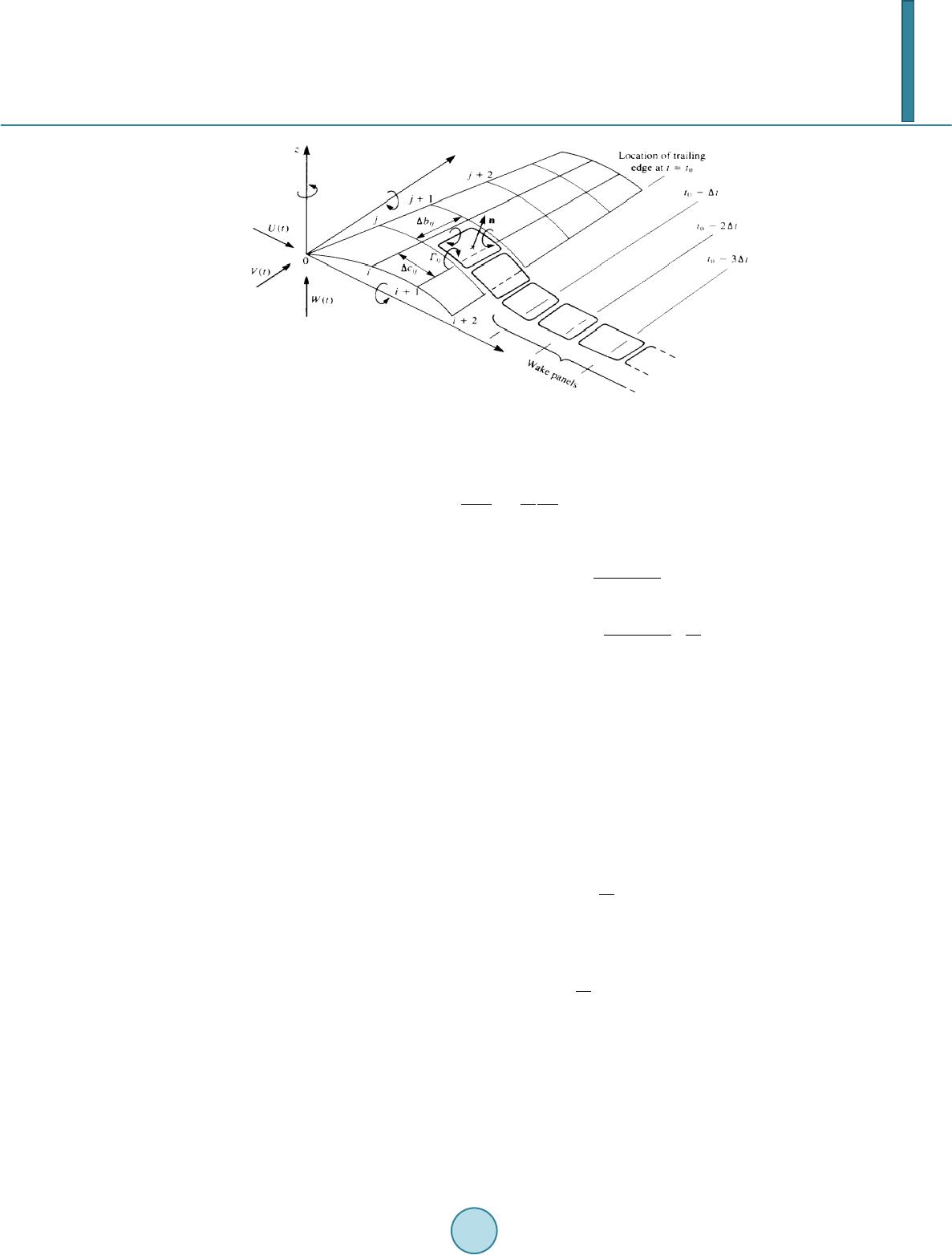 C. J. Yu et al. Figure 1. Diagrammatic drawing of vortex lattice method [16]. is the strength of the vortex. Since for this vortex ring model , (4) Substituting these terms into Equatio n (2) results in () ()( ) () ()( ) 1, ,1 ,, ,,. iji j ijWWW iij iji j WWW ijij ij ij PUtu Vtv Wtwc Utu Vtv Wtwbt ρτ τ − − Γ −Γ ∆ =+++⋅⋅ ∆ Γ −Γ∂ ++++ ⋅⋅+Γ ∆∂ (5) where , , are respectively the fluid velocities of direction, direction and direc- tion of inertial coordinate when time is moment, and , , are respectively the velocity of di- rection, direction and direction of body coordinate. The contribution of this panel to the loads is (6) whe r e is pressure of element, is area of element. The lift can be derived based on vector transfer [13], (7) The drag is the force component parallel to the flight direction and each panel contribution is ( ) ( ) ind 1, sin ij ijWiji jijijij ij Dwwb S t ρα − ∂ ∆=+Γ−Γ∆+∆ Γ ∂ ∑ (8) where is induced velocity of flapping wing. If the panel is at the leading edge then ( ) ind sin ij ijWij ijijij ij Dww bS t ρα ∂ ∆=+Γ∆ +∆ Γ ∂ ∑ (9) If forward flight velocity is constant, then (10) The total lift and thrust are obtained by integrating the contribution of each element. ( ) cos cos ijij ij LF αβ = ∆⋅ ∑ (11a) (11b)  C. J. Yu et al. 3. Production of Lift and Thrust In this paper, the motion of FWAV can be decomposed as pitching motion and flapping motion, as shown in Figure 2. These two motion varied with the time can be written as: (12a) (12b) where and respectively represent the mean angle of attack of pitching and flapping motion, and are defined as the amplitude of flapping and pitching motion respectively, is flapping frequency (Hz). The sketch of lift and thrust production during upstroke and down stroke is shown in Figure 3. A typical wing section is observed, and the aerodynamic force can be obtained by integrating the pressure of wing surface. The lift and thrust (drag) are the components of the aerodynamic force in the Y-axis and the nega- tive X-axis direction, respectively. Positive thrust and negative lift are produced during upstroke, positive lift and positive thrust are produced during down stroke. 4. Numerical Calculation The FMAV we studied is shown in Figure 4. The shape of flapping wing is approximate a quarter of ellipse, and the equation of ellipse is 22 1 0.08 0.17 xy += In order to calculate the lift and thrust, we assume original parameters of flapping wing motion are: , , , fluid velocity and . The lift curve and thrust curve can be calculated in a flapping period by using Equation (11), and as shown in Figure 5. Figure 5 shows that lift is mainly produced during down stroke, and drag is produced during upstroke. How- ever, thrust is produced during both do wn stroke and upstroke. The lift and thrust produced during down stroke are much more than that produced during upstroke. The average lift during one flapping period , and the average thrust in one period . 4.1. Effect of Flapping Frequency on Lift and Thrust In order to study the effect of flapping frequency on lift and thrust, is changed to 4.3 Hz, 6.3 Hz, 7.1 Hz and 7.9 Hz respectively, and other parameters are as same as the original parameters. Figure 6 is the lift comparison of experiment result and numerical result, and Figure 7 is the thrust compari- son of experiment result and numerical result. Figure 6 and Fig ure 7 show that the lift and thrust increase with the increase of flapping frequency. To fly higher and faster, birds can increase their flapping frequency, and it means birds need consume more internal ener gy. 4.2. Effect of Flapping Amplitude on Lift and Thrust In order to study the effect of flapping amplitude on lift and thrust, is changed respectively to 37.5˚, 40˚, 45˚ and 47.5˚, and other parameters are as same as the original parameters. Figure 8 shows that thrust increases with the increase of flapping amplitude, but the lift decreases with the increase of flapping amplitude. Birds can increase flapping amplitude to produce more thrust to increase flight velocity, but the weight of bird changes little, so the coefficient of lift decreases. 4.3. Effect of Mean Pitching Angle on Lift and Thrus t In order to study the effect of mean pitching angle on lift and thrust, is changed respectively to 2.5˚, 5˚, 10˚ and 12.5 ˚, and other parameters are as same as the original parameters. 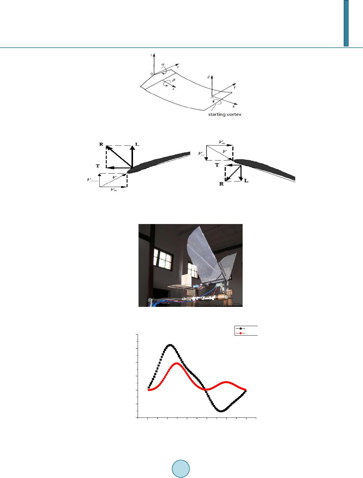 C. J. Yu et al. Figure 2. Motion with pitching and flapping [17] . (a) (b) Figure 3. Sketch of lift and thrust production during upstroke and downstroke. (a) downstroke; (b) upstroke. Figure 4. FM AV. 0.0 0.2 0.4 0.6 0.8 1.0 -40 -20 0 20 40 60 80 Aerodynamic Force /g t/T Lift Thrust Figure 5. Lift and thrust curve in one flapping period. 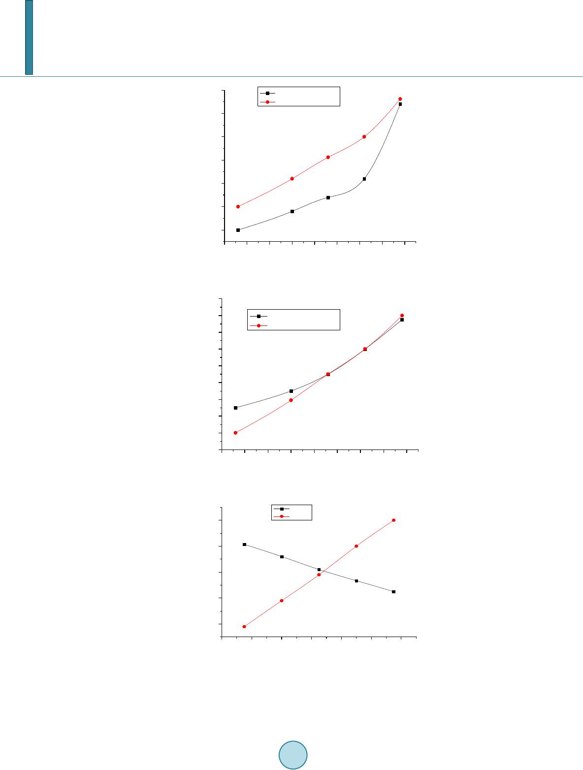 C. J. Yu et al. 4.0 4.5 5.0 5.5 6.0 6.5 7.0 7.5 8.0 11.0 11.5 12.0 12.5 13.0 13.5 14.0 Experiment Result[18] Calculation Result Average lift /g Flapping frequency /HZ Figure 6. Effect of flapping frequency on lift. 4.0 4.5 5.0 5.5 6.0 6.5 7.0 7.5 8.0 6 8 10 12 14 16 18 20 22 24 Average thrust /g Flapping frequency /HZ Experiment Result [18] Calculation Result Figure 7. Effect of flapping frequency on thrust. 36 38 40 42 44 46 48 10 11 12 13 14 Average aerodynamic force /g Flapping Amplitude / 0 Lift Thrust Figure 8. Effect of flapping amplitude on lift and thrust. Figure 9 shows that the lift and thrust increase with the increase of mean pitching angle, but the effect on lift is much more than on thrust. To obtain much more lift, birds need increase mean pitching angle. 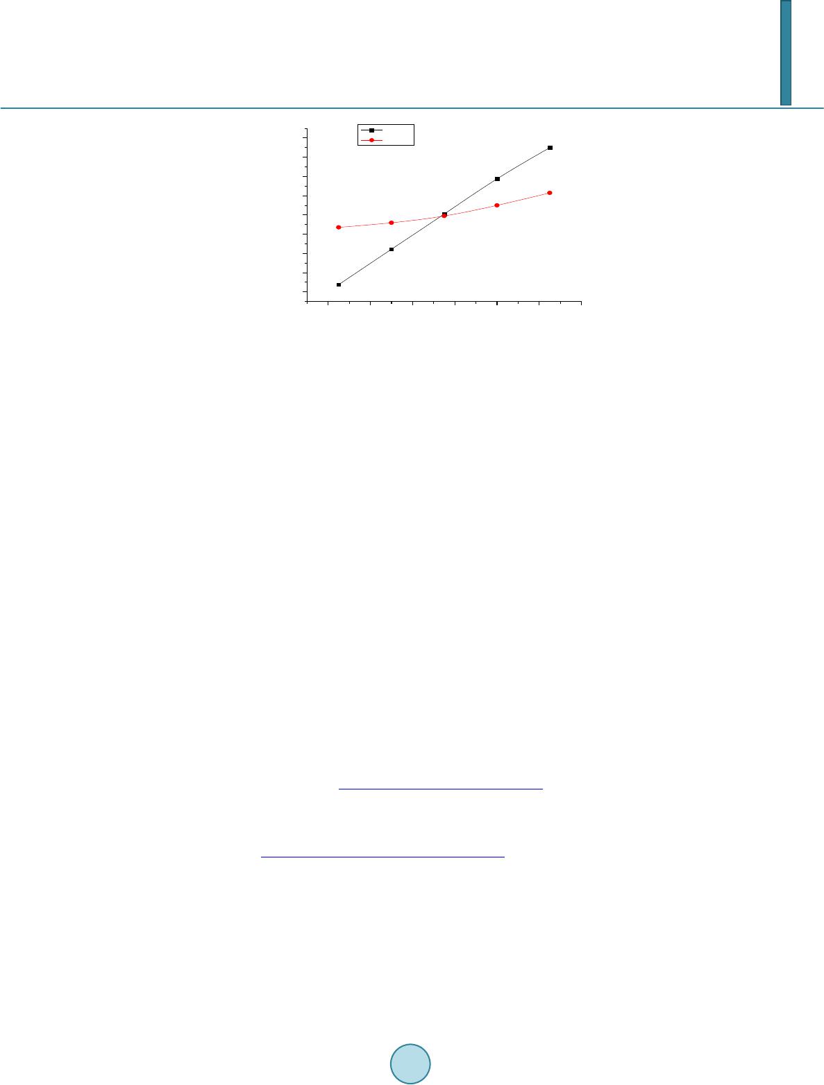 C. J. Yu et al. 246810 12 14 4 6 8 10 12 14 16 18 20 Average aerodynamic force /g Mean pitching angle / 0 Lift Thrust Figure 9. Effect of mean pitching angle on lift and thrust. 5. Conclusions Three-dimension unsteady vortex lattice method is applied to study the lift and thrust of FWAV with pitching and flapping motion. The following conclusions can be reached based on this study: 1) Lift is mainly produced during down stroke; however, thrust is produced during both down stroke and up- stro ke. The lift and thrust produced during down stroke are much more than that produced during upstroke. 2) Lift and thrust increase with the increase of flapping frequency; 3) Thrust increases with the increase of flapping amplitude, but the lift decreases with the increase of flapping amplitude; 4) Lift and thrust increase with the increase of mean pitching angle, but the effect on lift is much more than on thrust. This research is helpful to understand the flight mechanism of birds, thus improving the design of FWAV si- mulating birds. In the future we will continue the aerodynamic study of FWAV, such as 1) how the bound vor- tex and wake vortex affect the thrust in Equation (8); 2) which vortex is mainly to produce thrust; 3) effect of the section of flapping wing on aerodynamic force. Acknowledgem ents This work is financially supported by Embry-Riddle Aeronautical University, Jiangxi Provincial Department of Education (GJJ12412) and Doctorate Research Foundation of Nanchang Hang kong University (EA201006045). References [1] Wei s-Fogh, T. (1973) Quick Estimates of Flight Fitness in Hovering Animals, including Novel Mechanisms for Lift Pro duct ion . Journal of Experimental Biology, 59, 169-230. [2] Ellington, C.P. (1984 ) The Aerodynamics of Hovering Flight. IV. Aerodynamic Mech anis ms. Philosophical Transac- tions of Royal Society B, 305, 79-113. http://dx.doi.org/10.1098/rstb.1984.0052 [3] Dickinson, M.H. (1994) The Effects of Wing Rotation on Unsteady Aerodynamic Performance at Low Reynolds Numbers. Journal of Experimental Biology, 192, 179-206. [4] Dickinson, M.H., Lehmann, F. and Sane, S.P. (1999) Wing Rotation and the Aerodynamic Basis of Insect Flight. Sci- ence, 284 , 1954-1960. http://dx.doi.org/10.1126/science.284.5422.1954 [5] Kesel, A.B. (2000) Aerodynamic Characteristics of Dragonfly Wing Sections Compared with Technical Aerofoils. Journal of Experimental Biology, 203, 3125-3135 . [6] Sh y y, W. , Berg, M. and Lju ngqvi st, D. (1999) Flapping and Flexible Wings for Biological and Micro Air Vehicles. Progress in Aerospace Sciences, 35, 455 -505. [7] Oba lske, B.W. and Dial, K.P. (1996) Flight Kinematics of Black-Billed Magpies and Pigeons over a Widerange of Speed s. Journal of Experimental Biology, 199, 2 63-28 0 . [8] Jon es, K.D., Duggan , S.J. and Platzer, M.F. (2011) Flapping-Wing Propulsion for a Micro Air Vehicle. The 39th Aer- ospace Sciences Meeting & Exhibit, Reno, 8-11 January 2001.  C. J. Yu et al. [9] Heath cote, S., Wan g, Z. and Gursul, I. (2008) Effect of Spanwise Flexibility on Flapping Wing Propulsion. Journal of Fluids and Structures, 24, 183-199. http://dx.doi.org/10.1016/j.jfluidstructs.2007.08.003 [10] Stewart, E.C., Patil, M.J. and Canfield, R. A. (2014) Aeroelastic Shape Optimization of a Flapping Wing. The 10th AIAA Multidisciplinary Design Optimization Conference, 13-17 January 2014, National Harbor. http://dx.doi.org/10.2514/6.2014-0469 [11] Smith, M.J.C., Wilkin, P.J. and Williams, M.H. (1996) The Advantages of an Unsteady Panel Method in Modeling the Aerodynamic Forces on a Rigid Flapping Wings. Journal of Experimental Biology, 199 , 1073-108 3. [12] Fitzger ald, C., Valdez, M. and Balachand ran (2011) A Comparison of Computational Models for Fluid-Structure Inte- raction Studies of Flexible Flapping Wing Systems. The 49th AIAA Aerospace Sciences Meeting including the New Horizons Forum and Aerospace Exposition, Orlando, 4-7 January 2011. [13] Yu, C., An g , H., Chen, Q., et al. (2008) Three-Dimension Unsteady Vortex Lattice Method for Flexible Structure Flap- ping-Wing Aerial Vehicle. Journal of Nanjing University of Aeronautics and Astronautics, 40, 451-455. [14] Mazaher i, K. and Ebrahimi, A. (2011) Experimental Investigation on Aerodynamic Performance of a Flapping Wing Vehicle in Forward Flight. Journal of Fluids and Structures, 27, 586-595 . http://dx.doi.org/10.1016/j.jfluidstructs.2011.04.001 [15] Muniappan, A. (2005) Lift and Thrust Characteristics of Flapping Wing Micro Air Vehicle(MAV). The 43rd AIAA Aerospace Sciences Meeting and Exhibit, Reno, 10-13 January 2005. http://dx.doi.org/10.2514 /6. 2005 -10 55 [16] Katz, J. and Plotkin, A. (2001) Low-Speed Aerodynamics. 2nd Editio n , Ca mbr idge University Press, New York. http://dx.doi.org/10.1017/CBO9780511810329 [17] Yu, C. (20 09 ) Numerical Study of Aerodynamics for Flexible Membrane Flapping-Wing Aerial Vehicle. P h.D. The si s , Nanjing University of Aeronautics and Astronautics, Nanjing. [18] Zen g, R. (2005) Aerodynamic Characteristics of Flapping-Wing MAV Simulating Bird Flight. P h.D . Th es is , Nanjing University of Aeronautics and Astronautics, Nanjing.
|