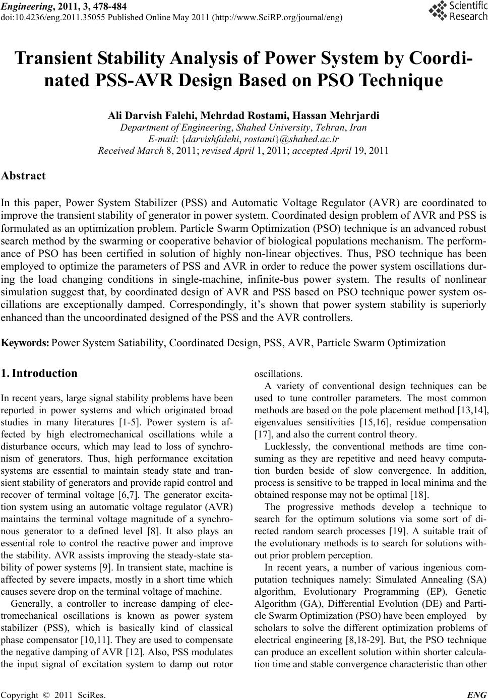
 Engineering, 2011, 3, 478-484 doi:10.4236/eng.2011.35055 Published Online May 2011 (http://www.SciRP.org/journal/eng) Copyright © 2011 SciRes. ENG Transient Stability Analysis of Power System by Coordi- nated PSS-AVR Design Based on PSO Technique Ali Darvish Falehi, Mehrdad Rostami, Hassan Mehrjardi Department of Engineering, Shahed University, Tehran, Iran E-mail: {darvishfalehi, rostami}@shahed.ac.ir Received March 8, 2011; revised April 1, 2011; accepted April 19, 2011 Abstract In this paper, Power System Stabilizer (PSS) and Automatic Voltage Regulator (AVR) are coordinated to improve the transient stability of generator in power system. Coordinated design problem of AVR and PSS is formulated as an optimization problem. Particle Swarm Optimization (PSO) technique is an advanced robust search method by the swarming or cooperative behavior of biological populations mechanism. The perform- ance of PSO has been certified in solution of highly non-linear objectives. Thus, PSO technique has been employed to optimize the parameters of PSS and AVR in order to reduce the power system oscillations dur- ing the load changing conditions in single-machine, infinite-bus power system. The results of nonlinear simulation suggest that, by coordinated design of AVR and PSS based on PSO technique power system os- cillations are exceptionally damped. Correspondingly, it’s shown that power system stability is superiorly enhanced than the uncoordinated designed of the PSS and the AVR controllers. Keywords: Power System Satiability, Coordinated Design, PSS, AVR, Particle Swarm Optimization 1. Introduction In recent years, large signal stability problems have been reported in power systems and which originated broad studies in many literatures [1-5]. Power system is af- fected by high electromechanical oscillations while a disturbance occurs, which may lead to loss of synchro- nism of generators. Thus, high performance excitation systems are essential to maintain steady state and tran- sient stability of generators and provide rapid control and recover of terminal voltage [6,7]. The generator excita- tion system using an automatic voltage regulator (AVR) maintains the terminal voltage magnitude of a synchro- nous generator to a defined level [8]. It also plays an essential role to control the reactive power and improve the stability. AVR assists improving the steady-state sta- bility of power systems [9]. In transient state, machine is affected by severe impacts, mostly in a short time which causes severe drop on the terminal voltage of machine. Generally, a controller to increase damping of elec- tromechanical oscillations is known as power system stabilizer (PSS), which is basically kind of classical phase compensator [10,11]. They are used to compensate the negative damping of AVR [12]. Also, PSS modulates the input signal of excitation system to damp out rotor oscillations. A variety of conventional design techniques can be used to tune controller parameters. The most common methods are based on the pole placement method [13,14], eigenvalues sensitivities [15,16], residue compensation [17], and also the current control theory. Lucklessly, the conventional methods are time con- suming as they are repetitive and need heavy computa- tion burden beside of slow convergence. In addition, process is sensitive to be trapped in local minima and the obtained response may not be optimal [18]. The progressive methods develop a technique to search for the optimum solutions via some sort of di- rected random search processes [19]. A suitable trait of the evolutionary methods is to search for solutions with- out prior problem perception. In recent years, a number of various ingenious com- putation techniques namely: Simulated Annealing (SA) algorithm, Evolutionary Programming (EP), Genetic Algorithm (GA), Differential Evolution (DE) and Parti- cle Swarm Optimization (PSO) have been employed by scholars to solve the different optimization problems of electrical engineering [8,18-29]. But, the PSO technique can produce an excellent solution within shorter calcula- tion time and stable convergence characteristic than other  A. D. FALEHI ET AL.479 stochastic techniques [8]. In fact, PSO is a stochastic global optimization approach based on swarm behavior such as fish and bird schooling in nature [30]. Generally, PSO is known as a simple concept, easy to perform, and computationally effective. PSO has a flexible and well-balanced mechanism to enhance the global and lo- cal exploration abilities [31]. Thus, PSO technique has been selected to coordinate the operation of both the PSS and AVR controllers in order to improve the transient stability and diminish the power system oscillations. To appraise the coordinated design problem of these devices, a severe disturbance condition is considered in the transmission line of single-machine, infinite-bus power system. Furthermore, effect of coordinated design of these devices is assessed in spite of changes in the loading of the generator. 2. Power System Structure and Modeling The model of electrical power system is exhibited in Fig- ure 1, which is comprised of a generating unit connected to electrical network through a transformator. It is almost similar to the power system used in [23]. The generator is equipped with hydraulic turbine and governor (HTG). Also, excitation system furnished with an automatic voltage regulator (AVR) and a power system stabilizer (PSS) to maintain the terminal voltage and to damp os- cillations. Speed deviation of generator is chosen as the input signal of the PSS. The single-machine, infinite-bus power system has been simulated using MAT- LAB/SIMULINK environment. All of the other relevant parameters are given in Appendix. 2.1. Automatic Voltage Regulator Model A first order AVR model is used in this paper which is almost derived from ref [5,32]. The block diagram of the model is shown in Figure 2. The parameters to be adjusted, on the model of AVR presented in Figure 2, are: the gain Ka and the time con- stant Ta. The values of the parameters: Kf, Tf and Tr are considered 0.001, 0.1 and 0.02 respectively [33]. 2.2. Power System Stab ilizer Mode l PSS includes a transfer function comprise of an amplifi- cation block, a wash out block and lead-lag block and sensor time constant [12,19]. The PSS input signal can be either the speed deviation or active power. The struc- ture of the PSS controller is presented in Figure 3. The value of TWS and sensor delay time are considered 3 and 15 ms respectively. Parameters of the power system sta- bilizer, including: gain (KP) and the time constants (T1P and T2P) shall be determined. 2.3. Coordinated Design of AVR and PSS In this study, the PSS and AVR controller are designed and optimized by minimizing objective function in order to enhance the system response in terms of the settling time, overshoots and undershoot. There are many differ- ent methods to appraise the response performance of a control system, for example: integral of time weighted absolute value of error (ITAE), integrated absolute er- ror(IAE), integral of squared error (ISE), and integral of time weighted squared error (ITSE) [34]. In this paper, the integral time absolute error (ITAE) of the speed signal deviation is considered as the fitness function J [18]. This fitness function is determined as: sin 0.. tt t tdt (1) where, is the speed deviation in and sin is the time range of the simulation. The time-domain simulation of the nonlinear system model was performed for the simu- lation period. It is aimed to minimize this fitness function in order to improve the system response in terms of the settling time and overshoots. The problem constraints are the PSS and AVR parameter bounds. Therefore, the design t Figure 1. Single-machine, infinite-bus power sys tem. Copyright © 2011 SciRes. ENG 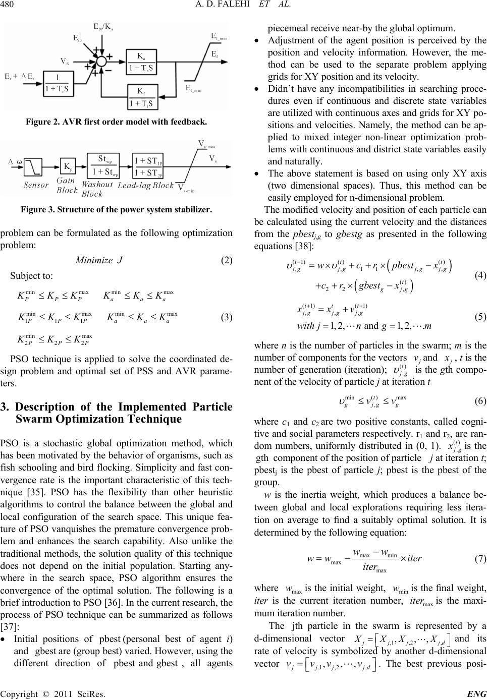 A. D. FALEHI ET AL. Copyright © 2011 SciRes. ENG 480 Figure 2. AVR first order model with feedback. Figure 3. Structure of the power system stabilizer. problem can be formulated as the following optimization problem: M inimize J (2) Subject to: min max PPP KKK min max aaa KKK min max 111 PP KKK (3) min max aaa KKK min max 222 PP KKK PSO technique is applied to solve the coordinated de- sign problem and optimal set of PSS and AVR parame- ters. 3. Description of the Implemented Particle Swarm Optimization Technique PSO is a stochastic global optimization method, which has been motivated by the behavior of organisms, such as fish schooling and bird flocking. Simplicity and fast con- vergence rate is the important characteristic of this tech- nique [35]. PSO has the flexibility than other heuristic algorithms to control the balance between the global and local configuration of the search space. This unique fea- ture of PSO vanquishes the premature convergence prob- lem and enhances the search capability. Also unlike the traditional methods, the solution quality of this technique does not depend on the initial population. Starting any- where in the search space, PSO algorithm ensures the convergence of the optimal solution. The following is a brief introduction to PSO [36]. In the current research, the process of PSO technique can be summarized as follows [37]: Initial positions of pbest(personal best of agent i) and gbest are (group best) varied. However, using the different direction of pbest and gbest, all agents piecemeal receive near-by the global optimum. Adjustment of the agent position is perceived by the position and velocity information. However, the me- thod can be used to the separate problem applying grids for XY position and its velocity. Didn’t have any incompatibilities in searching proce- dures even if continuous and discrete state variables are utilized with continuous axes and grids for XY po- sitions and velocities. Namely, the method can be ap- plied to mixed integer non-linear optimization prob- lems with continuous and district state variables easily and naturally. The above statement is based on using only XY axis (two dimensional spaces). Thus, this method can be easily employed for n-dimensional problem. The modified velocity and position of each particle can be calculated using the current velocity and the distances from the pbestj,g to gbestg as presented in the following equations [38]: (1) ()() ,,11, () 22 , tt , t gjg jg t gjg wcrpbestx crgbest x jg (4) (1) (1) ,,, 1,2, and 1,2,. ttt jgjg jg xxv with jngm (5) where n is the number of particles in the swarm; m is the number of components for the vectors vand , t is the number of generation (iteration); () , t g is the gth compo- nent of the velocity of particle j at iteration t min( )max , t gjgg vv (6) where c1 and c2 are two positive constants, called cogni- tive and social parameters respectively. r1 and r2, are ran- dom numbers, uniformly distributed in (0, 1). () , t g is the component of the position of particle at iteration t; pbestj is the pbest of particle j; pbest is the pbest of the group. gth j w is the inertia weight, which produces a balance be- tween global and local explorations requiring less itera- tion on average to find a suitably optimal solution. It is determined by the following equation: max min max max ww w witer iter (7) where max is the initial weight, min is the final weight, iter is the current iteration number, is the maxi- mum iteration number. w w it max er The particle in the swarm is represented by a d-dimensional vector ,1 ,2,d and its rate of velocity is symbolized by another d-dimensional vector jth ,,, jjjj XXX X , , ,1 ,2 ,, jj vjd vvv . The best previous posi- 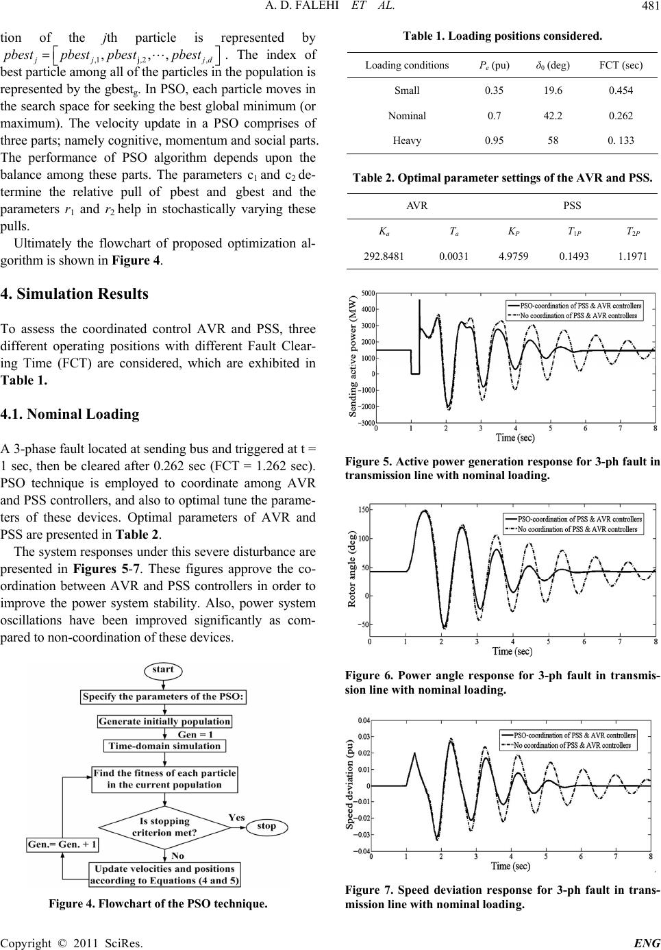 A. D. FALEHI ET AL.481 tion of the jth particle is represented by ,1 j,2, ,,, j pbestpbest pbestpbest jd . The index of best particle among all of the particles in the population is represented by the gbestg. In PSO, each particle moves in the search space for seeking the best global minimum (or maximum). The velocity update in a PSO comprises of three parts; namely cognitive, momentum and social parts. The performance of PSO algorithm depends upon the balance among these parts. The parameters c1 and c2 de- termine the relative pull of pbest and and the parameters r1 and r2 help in stochastically varying these pulls. gbest Ultimately the flowchart of proposed optimization al- gorithm is shown in Figure 4. 4. Simulation Results To assess the coordinated control AVR and PSS, three different operating positions with different Fault Clear- ing Time (FCT) are considered, which are exhibited in Table 1. 4.1. Nominal Loading A 3-phase fault located at sending bus and triggered at t = 1 sec, then be cleared after 0.262 sec (FCT = 1.262 sec). PSO technique is employed to coordinate among AVR and PSS controllers, and also to optimal tune the parame- ters of these devices. Optimal parameters of AVR and PSS are presented in Table 2. The system responses under this severe disturbance are presented in Figures 5-7. These figures approve the co- ordination between AVR and PSS controllers in order to improve the power system stability. Also, power system oscillations have been improved significantly as com- pared to non-coordination of these devices. Figure 4. Flowchart of the PSO technique. Table 1. Loading positions considered. Loading conditions Pe (pu) δ0 (deg) FCT (sec) Small 0.35 19.6 0.454 Nominal 0.7 42.2 0.262 Heavy 0.95 58 0. 133 Table 2. Optimal parameter settings of the AVR and PSS. AVR PSS Ka T a K P T 1P T2P 292.8481 0.0031 4.9759 0.1493 1.1971 Figure 5. Active power generation response for 3-ph fault in trans m ission line with no minal loading. Figure 6. Power angle response for 3-ph fault in transmis- sion line with nominal loading. Figure 7. Speed deviation response for 3-ph fault in trans- mission line with nominal loading. Copyright © 2011 SciRes. ENG 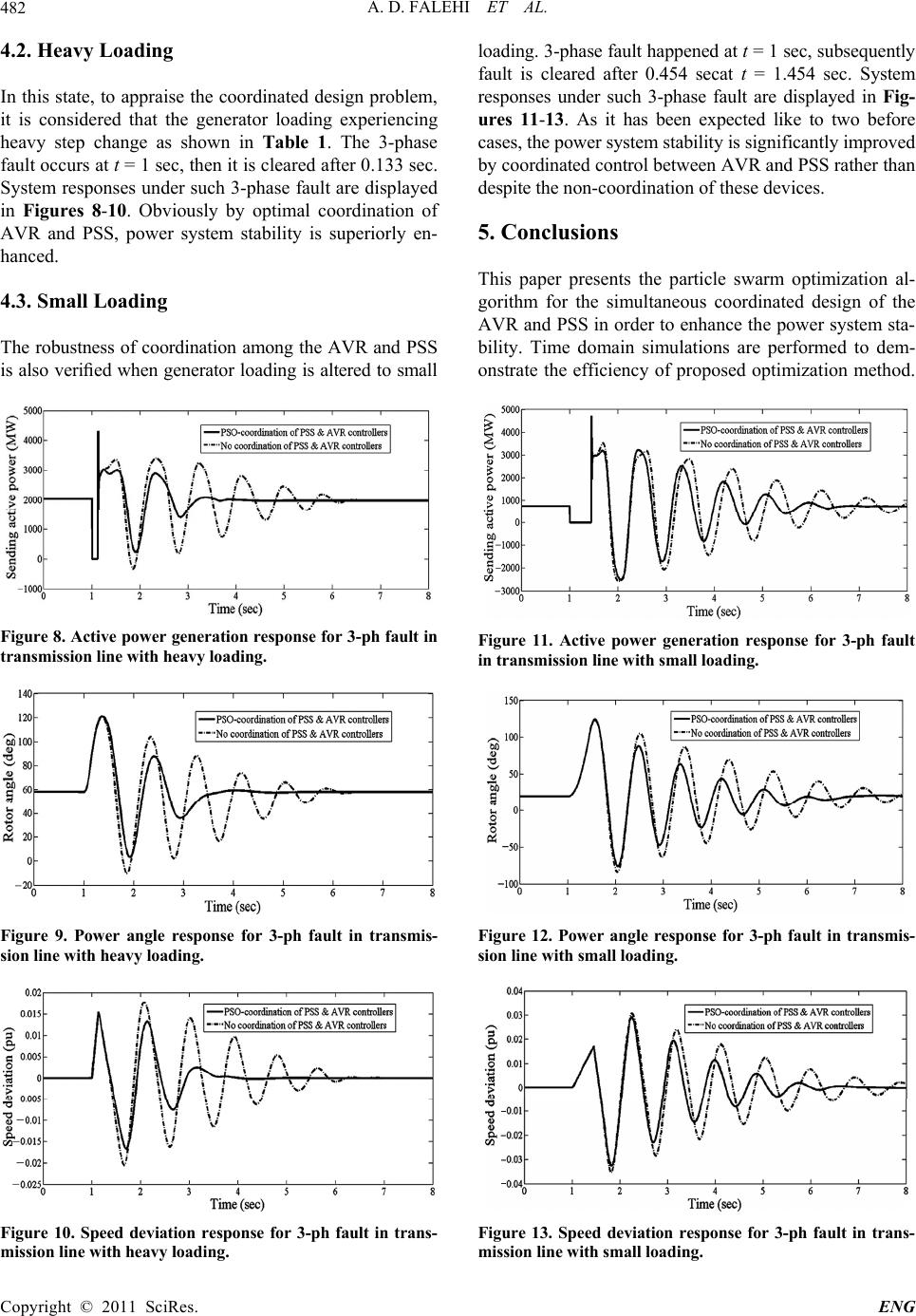 A. D. FALEHI ET AL. 482 4.2. Heavy Loading In this state, to appraise the coordinated design problem, it is considered that the generator loading experiencing heavy step change as shown in Table 1. The 3-phase fault occurs at t = 1 sec, then it is cleared after 0.133 sec. System responses under such 3-phase fault are displayed in Figures 8-10. Obviously by optimal coordination of AVR and PSS, power system stability is superiorly en- hanced. 4.3. Small Loading The robustness of coordination among the AVR and PSS is also verified when generator loading is altered to small Figure 8. Active power generation response for 3-ph fault in transmission line with heavy loading. Figure 9. Power angle response for 3-ph fault in transmis- sion line with heavy loading. Figure 10. Speed deviation response for 3-ph fault in trans- mission line with heavy loading. loading. 3-phase fault happened at t = 1 sec, subsequently fault is cleared after 0.454 secat t = 1.454 sec. System responses under such 3-phase fault are displayed in Fig- ures 11-13. As it has been expected like to two before cases, the power system stability is significantly improved by coordinated control between AVR and PSS rather than despite the non-coordination of these devices. 5. Conclusions This paper presents the particle swarm optimization al- gorithm for the simultaneous coordinated design of the AVR and PSS in order to enhance the power system sta- bility. Time domain simulations are performed to dem- onstrate the efficiency of proposed optimization method. Figure 11. Active power generation response for 3-ph fault in transmission line with small loading. Figure 12. Power angle response for 3-ph fault in transmis- sion line with small loading. Figure 13. Speed deviation response for 3-ph fault in trans- mission line with small loading. Copyright © 2011 SciRes. ENG  A. D. FALEHI ET AL.483 Coordination among these devices based on PSO tech- nique has been deeply investigated under severe distur- bance for single-machine, infinite-bus power system. To confirm the robustness of coordinated design of these controllers, power system stability has been assessed in spite of load changes of generator. Also, the particular features of PSO algorithm namely its superior computa- tion efficiency and high accuracy solutions have been approved. Finally, the results of non-linear simulation have shown that by using PSO technique, power system transient stability dramatically improves as compared to non-optimized parameters of PSS and AVR. 6. References [1] M. B. Duric, Z. M. Radojevic and E. D. Turkovic, “A Reduced Order Multi Machine Power System Model Suitable for Small Signal Stability Analysis,” Electrical Power and Energy Systems, Vol. 20, No. 5, 1998, pp. 369-374. [2] H. Yassami, A. Darabi and S. M. R. Rafiei, “Power Sys- tem Stabilizer Design Using Strength Pareto Multi-Objective Optimization Approach,” Electric Power Systems Research, Vol. 80. No. 7, 2010, pp. 838-846. doi:10.1016/j.epsr.2009.12.011 [3] V. Mukherjee and S. P. Ghoshal, “Comparison of Intelli- gent Fuzzy Based AGC Coordinated PID Controlled and PSS Controlled AVR System,” Electrical Power and En- ergy Systems, Vol. 29, No. 9, 2007, pp. 679-689. doi:10.1016/j.ijepes.2007.05.002 [4] S. Gomes Jr., N. Martins and C. Portela, “Computing Small-Signal Stability Boundaries for Large-Scale Power Systems,” IEEE Transactions on Power Systems, Vol. 18, No. 2, 2003, pp. 747-752. doi:10.1109/TPWRS.2003.811205 [5] C. Liu, R. Yokoyama, K. Koyanagi and K. Y. Lee, “PSS Design for Damping of Inter-Area Power Oscillations by Coherency-Based Equivalent Model,” Electrical Power and Energy Systems, Vol. 26, No.7, 2004, pp. 535-544. doi:10.1016/j.ijepes.2004.01.007 [6] F. P. Demello and C. Concordla, “Concepts of synchro- nous Machine Stability as Affected by Excitation Con- trol,” IEEE Transactions, Power Apparatus System, Vol. 88, No. 4, pp. 189-202, 1969. doi:10.1109/TPAS.1969.292452 [7] M. Klein, G. J. Rogers and P. Kundur, “A Fundamental Study of Inter-Area Oscillations in Power Systems,” IEEE Transaction on Power Systems, Vol. 6, No. 3, 1991, pp. 914-921. doi:10.1109/59.119229 [8] A. M. El-Zonkoly, A. A. Khalil and N. M. Ahmied, “Op- timal Tunning of Lead-Lag and Fuzzy Logic Power Sys- tem Stabilizers Using Particle Swarm Optimization,” Ex- pert Systems with Applications, Vol. 36, No. 2, 2009, pp. 2097-2106. doi:10.1016/j.eswa.2007.12.069 [9] E. R. C. Viveros, G. N. Taranto and D. M. Falcão, “Tun- ing of Generator Excitation Systems Using Me- ta-Heuristics,” IEEE Power Engineering Society General Meeting, Montreal, 16 October 2006, p. 6. doi:10.1109/PES.2006.1709524 [10] Z. Lubosuy, “Dual Input Quasi-Optimal PSS for Gener- ating Unit with Static Excitation System,” Power Plants and Power Systems Control, Vol. 5, 2006, pp. 267-272. doi:10.3182/20060625-4-CA-2906.00051 [11] T. R. Jyothsna and K. Vaisakh, “Design of a Decentral- ized Non-linear Controller for Transient Stability Im- provement under Symmetrical and Unsymmetrical Fault Condition: A comparative Analysis with SSSC,” IEEE Power Systems Conference and Exposition, 15-18 March 2009, Seattle, pp. 1-8. [12] P. Kunder, “Power System Stability and Control,” McGraw, Hill, New York, 2001 [13] P. S. Rao and I. Sen, “Robust Pole Placement Stabilizer Design Using Linear Matrix Inequalities,” IEEE Trans- actions on Power Systems, Vol. 15, No. 1, 2000, pp. 3035-3046. [14] M. A. Abido, “Pole Placement Technique for PSS and TCSC-Based Stabilizer Design Using Simulated Anneal- ing,” International Journal of Electrical Power and En- ergy Systems, Vol. 22, No. 8, 2000, pp. 543-554. doi:10.1016/S0142-0615(00)00027-2 [15] B. C. Pal, “Robust Pole Placement versus Root-Locus Approach in the Context of Damping Interarea Oscilla- tions in Power Systems,” IEE Proceedings on Generation, Transmission and Distribution, Vol. 49, No. 6, 2002, pp. 739-745. doi:10.1049/ip-gtd:20020659 [16] L. Rouco and F. L. Pagola, “An Eigenvalue Sensitivity Approach to Location and Controller Design of Control- lable Series Capacitor for Damping Power System Oscil- lations,” IEEE Transactions on Power Systems, Vol. 12, No. 4, 1997, pp. 1660-1666. doi:10.1109/59.627873 [17] M. E. About-Ela, A. A. Sallam, J. D. McCalley and A. A. Fouad, “Damping Controller Design for Power System Oscillations Using Global Signals,” IEEE Transactions on Power Systems, Vol. 11, No. 2, pp. 767-773, 1996. [18] S. Panda and N. P. Padhy, “Optimal Location and Con- troller Design of STATCOM for Power System Stability Improvement Using PSO,” Journal of the Franklin Insti- tute, Vol. 345, No. 2, 2008, pp. 166-181. doi:10.1016/j.jfranklin.2007.08.002 [19] R. L. Haupt and S. E. Haupt, “Practical Genetic Algo- rithms,” Wiley, New York, 2004 [20] G. Wang, M. Zhan, X. Xu and C. Jiang, “Optimization of Controller Parameters Based on the Improved Genetic Algorithms,” Proceedings of the 6th World Congress on Intelligence Control and Automation, 21-23 June 2006, Dalian, pp. 3695-3698. doi:10.1109/WCICA.2006.1713060 [21] Q. Y. Jiang, Y. J. Cao and S. J. Cheng, “A Genetic Ap- proach to Design a HVDC Supplementary Subsynchro- nous Damping Controller,” IEEE Transaction on Power Delivery, Vol. 20, No. 2. pp. 528-532, 2005. doi:10.1109/TPWRD.2004.838522 [22] Z. L. Gaing, “A Particle Swarm Optimization Approach for Optimum Design of PID Controller in AVR System,” Copyright © 2011 SciRes. ENG  A. D. FALEHI ET AL. Copyright © 2011 SciRes. ENG 484 IEEE Transactions on Energy Conversion, Vol. 19, No. 2, 2004, pp. 384-91. doi:10.1109/TEC.2003.821821 [23] S. Panda, S. C. Swain, P. K. Rautray, R. K. Malik and G. Panda, “Design and Analysis of SSSC-Based Supple- mentary Damping Controller,” Simulation Modelling Practice and Theory, Vol. 18, No. 9, 2010, pp. 1199-1213. doi:10.1016/j.simpat.2010.04.007 [24] M. A. Abido, “Simulated Annealing Based Approach to PSS and FACTS Based Stabilizer Tuning,” Electrical Power and Energy Systems, Vol. 22, No. 4, 2000, pp. 247-258. doi:10.1016/S0142-0615(99)00055-1 [25] C. C. A. Rajan, “A Solution to the Economic Dispatch Using EP Based SA Algorithm on Large Scale Power System,” International Journal of Power and Energy Sys- tems, Vol. 32, No. 6, 2010, pp. 583-591. [26] J. Yuryevich and K. P. Wong, “Evolutionary Program- ming Based Optimal Power Flow Algorithm,” IEEE Transactions on Power System, Vol. 14, No. 4, 1999, pp. 1245-1250. doi:10.1109/59.801880 [27] Q. H. Wu and J. T. Ma, “Power System Optimal Reactive Power Dispatch Using Evolutionary Programming,” IEEE Transactions on Power System, Vol. 10, No. 3, 1995, pp. 1243-1249. doi:10.1109/59.466531 [28] S. Panda, “Differential Evolutionary Algorithm for TCSC-Based Controller Design,” Simulation, Model, Practice and Theory, Vol. 17, No. 10, 2009, pp. 1618-1634. doi:10.1016/j.simpat.2009.07.002 [29] S. K. Wang, J. P. Chiou, C. W. Liu, “Parameters Tuning of Power System Stabilizers Using Improved Ant Direc- tion Hybrid Differential Evolution,” International Jour- nal of Electrical Power and Energy Systems, Vol. 31, No. 1, 2009, pp. 34-42. doi:10.1016/j.ijepes.2008.10.003 [30] J. Kennedy and R. C. Eberhart, “Particle Swarm Optimi- zation,” Proceedings of IEEE International Conference of Neural Networks, Vol. 4, 1995, pp. 1942-1948. doi:10.1109/ICNN.1995.488968 [31] H. Shayeghi, A. Safari and H. A. Shayanfar, “PSS and TCSC Damping Controller Coordinated Design Using PSO in Multi-Machine Power System,” Energy Conver- sion and Management, Vol. 51, No. 12, 2010, pp. 2930-2937. doi:10.1016/j.enconman.2010.06.034 [32] Luonan Chen, Hideya Tanaka , Kazuo Katou , Yoshiyuki Nakamura., “Stability analysis for digital controls of power systems,” Electric Power Systems Research , Vol. 55, No. 2, pp. 79-86, 2000. doi:10.1016/S0378-7796(99)00097-8 [33] R. C. Eberhart, J. Kennedy and Y. Shi, “Swarm Intelli- gence,” Morgan Kaufman Publishers, San Francisco, 2001. [34] C. T. Chen, “Analog and Digital Control Design: Trans- fer Function, Space State, and Algebraic Methods,” Ox- ford University Press, Cambridge, 1993. [35] G. I. Rashed, H. I. Shaheen, X. Z. Duan and S. J. Cheng, “Evolutionary Optimization Techniques for Optimal Lo- cation and Parameter Setting of TCSC under Single Line Contingency,” Applied Mathematics and Computation, Vol. 205, pp. 133-147, 2008. [36] Y. J. Liu and X. X. He, “Modeling Identification of Power Plant Thermal Process Based on PSO Algorithm,” 2005 American Control Conference, 8-10 June 2005, Portland, pp. 4484-4489. [37] J. Kennedy and R. Eberhart, “Swarm Intelligence,” 1st Edition, Academic press, San Diego, 2001. [38] Panda, N. P. Padhy, “Comparison of particle swarm optimization and genetic algorithm for FACTS- based controller design,” Applied Soft Computing, Vol. 8, No. 4, 2008, pp. 1418-1427. doi:10.1016/j.asoc.2007.10.009 Appendix Transmission line: 3-Ph, 60 Hz, Length = 300 km each, R1 = 0.02546 Ω/km, R0 = 0.3864 Ω/km, L1 = 0.9337e − 3 H/km, L0 = 4.1264e − 3 H/km, C1 = 12.74e − 9 F/km, C0 = 7.751e − 9 F/km. Single-machine infinite-bus power system Generator: Hydraulic turbine and governor: Ka= 3.33, Ta= 0.07, Gmin= 0.01, Gmax= 0.97518, Vgmin= –0.1 p.u./s, Vgmax= 0.1 p.u./s, SB = 2100 MVA, H = 3.7 s, VB = 13.8 kV, f = 60 Hz, RS = 2.8544e − 3, d=1.305 p.u., Xd = 0.296 p.u., d =0.252 p.u., q = 0.474 p.u., q = 0.243 p.u., q = 0.18 p.u., = 1.01 s, = 0.053 s, d Td Tqo T = 0.1 s. Rp = 0.05, Kp = 1.163, Ki = 0.105, Kd = 0, Td = 0.01 s, β= 0, Tw = 2.67 s. Load at Bus-2: 250 MW. PSSs: sensor time constant = 0.015 s, VS max = 0.15 p.u., VS min = −0.15 p.u. Transformer: 2100 MVA, 13.8/500 kV, 60 Hz, R1 = R2 = 0.002 p.u., L1= 0, L2= 0.12 p.u., D1/Yg connection, Rm = 500 p.u., Lm = 500 p.u.
|