 Journal of Computer and Communications, 2014, 2, 25-33 Published Online November 2014 in SciRes. http://www.scirp.org/journal/jcc http://dx.doi.org/10.4236/jcc.2014.213004 How to cite this paper: Dung, L.-R., Sun, S.-T. and Wu, Y.-Y. (2014) Implementation of Shock Filter for Digital X-Ray Image Processing. Journal of Computer and Communications, 2, 25-33. http://dx.doi.org/10.4236/jcc.2014. 213004 Implementation of Shock Filter for Digital X-Ray Image Processing Lan-Rong Dung1, Shang-Ting Sun1, Yin-Yi Wu2 1Departmentof Electrical and Computer Engineering, National Chiao Tung Universi ty , Hsinchu, Chinese Taipei 2Chung-Shan Institute of Science Technology, Taoyuan, Chinese Taipei Email: lennon@faculty.nctu.edu.tw Received 16 September 2014 Abstract X-ray image might be corrupted by noise or blurring because of signal transmission or the bad X- ray lens. This paper presents a two-stage shock filter based on Partial Differential Equations (PDE) to restore noisy blurred X-ray image. Shock filters are popular morphological methods. They are used for noise removal, edge enhancement and image segmentation. Our experimental results show that the performances of shock filter are excellent in X-ray image. The peak signal-to-noise ratio (PSNR) values are 38 dB at least in restoring the noisy X-ray image. The sharpness of image’s edges increase in enhancing the blurred X-ray image. Furthermore, this paper proposes a VLSI architecture for accelerating the high-definition (HD) X-ray image (944 p) process. This paper im- plements the architecture in FPGA. The hardware cost is low because the computation of shock filter is low complex. To achieve the real-time processing specification, this paper uses a 5-series shock filter architecture to implement computation of HD X-ray image. This paper demonstrates a 944 p, 43.1-fps solution on 100 MHz with 133 k gate counts in Design Compiler, and with 2904 logic elements in FPGA. Keywords Shock Filter, X-Ray Image, VLSI, Image Processing 1. Introduction Shock filters are morphological method, and it “shocks” an image iteratively by dilation and erosion to create ruptures at the edge pixels [1]. This process makes shock filters applied to edge enhancement and segmentation. The algorithms are based on PDE. The original shock filter [2] has been developed in 1990, and it can’t remove noise. Therefore, an anisotropic diffusion filter [3] has been proposed to remove the noise. The diffusion can remove not only noise but details of image. However, most of X-ray images are smooth and lack of details. Edge enhancement and segmentation are important for medical image. Shock filter is applicable to process X-ray image. Furthermore, the portable devices might be applied with X-ray technique. We expect the processing time of shock filter can achieve the real time specification. In this paper, we propose a restoration method of X-ray im- 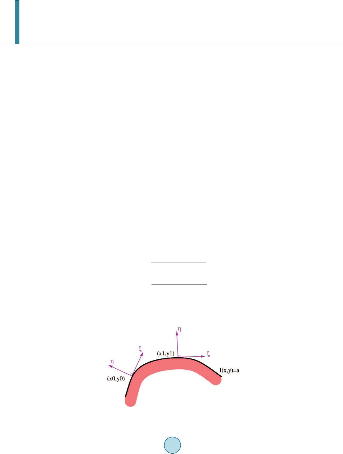 L.-R. Dung et al. age by using the shock filter. The performances of removing noise show that the method is much better than median filter, and that the value of PSNR and SSIM is very high in any types of noise. The remainder of this paper is organized as follows. We first present shock filter algorithm in Section 2. Then, we present simulation results in Section 3. Section 4 shows a VLSI architecture. Finally, a conclusion is made in Section 5. 2. Shock Filter Algorithm In this section, we will present shock filter algorithm in detail. Firstly, the X-ray images need to be noise-free images. In order to remove noise of X-ray image, we propose an anisotropic diffusion filter, and it’s an adaptive smoothing technique. Secondly, shock filter algorithm is proposed for the X-ray image segmentation and en- hancement. Finally, a two-stage shock filter is proposed to optimize the result of shock processing. 2.1. Anisotropic Diffusion Filter According to [4], the diffusion is a process that equilibrates differences. The equilibration feature is expressed by Fick’s law: (1) The equation shows a flux J which aim to equilibrate differences. The relation between the gradient of pixel value ∇I and J is the diffusion tensor D. The change of pixel value is expressed by the continuity equation: (2) where t is the time. Then, we plug in Fick’s law into the continuity equation, and get the anisotropic diffusion equation. There is a typical anisotropic diffusion filter [5], as in: (3) and are the second-order directional derivatives in the directions of gradient η and contour ε, shown in Figure 1, and can be represented as 22 xxyxy xyyy x εε 22 xy II2I I III III −+ =+ 22 xx xxy xyyy y ηη 22 xy II2I I III I. II ++ =+ (4) In the denoising case, preserving the image contour is important. For this reason, we can’t diffuse the image crossing the contour, but diffuse the image following the contour direction. For Another reason, the contour di- rection differences of noise are very large because the noise is usually a spot. Figure 1. Directions of contour and gradient [6]. 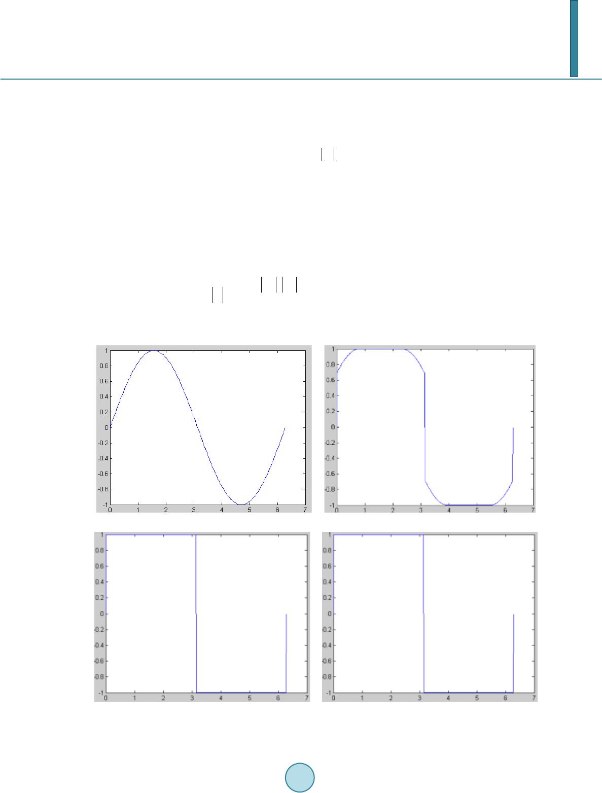 L.-R. Dung et al. 2.2. Anisotropic Diffusion Filter The shock filter processes dilating or eroding around the local maxima or the local minima of pixel value. Ite- rating this process leads the image to a segmented result, and segments are separated by discontinuities. The formulation of shock filter [ 7] equation is: (5) The shock filter performs morphological operators depending on the sign of . is positive or negative around the local maxima or the local minima, and the sign changes at the edge of image. The absolute value of is the weight. The weight at the extreme pixel is zero, so the extreme value won’t change after processing. In Fig ure 2, we can observe the signal change with the iterative shock process. However, the absolute value of is not an ideal weight. The weight is too large at the edge, and isn’t zero at all local extreme pixel. Then, the local extrema will be created and change after processing, shown in Figure 3. To avoid the divergent result, we generate weight by using the semi-discrete model [2]. The equation is: ( ) ( )( ) ( )( ) xxx x x xx minI,I,sign Isign I0 I. 0,sign Isign I0 +−+ − +− ⋅> =⋅< (6 ) and are the gradient of pixel’s right and left side. If the pixel is the local extrema, the value will (a) (b) (c) (d) Figure 2. Results of iterative shock process. (a) Original signal; (b) 75 time s; (c) 150 ti me s ; (d) 1000 ti mes. 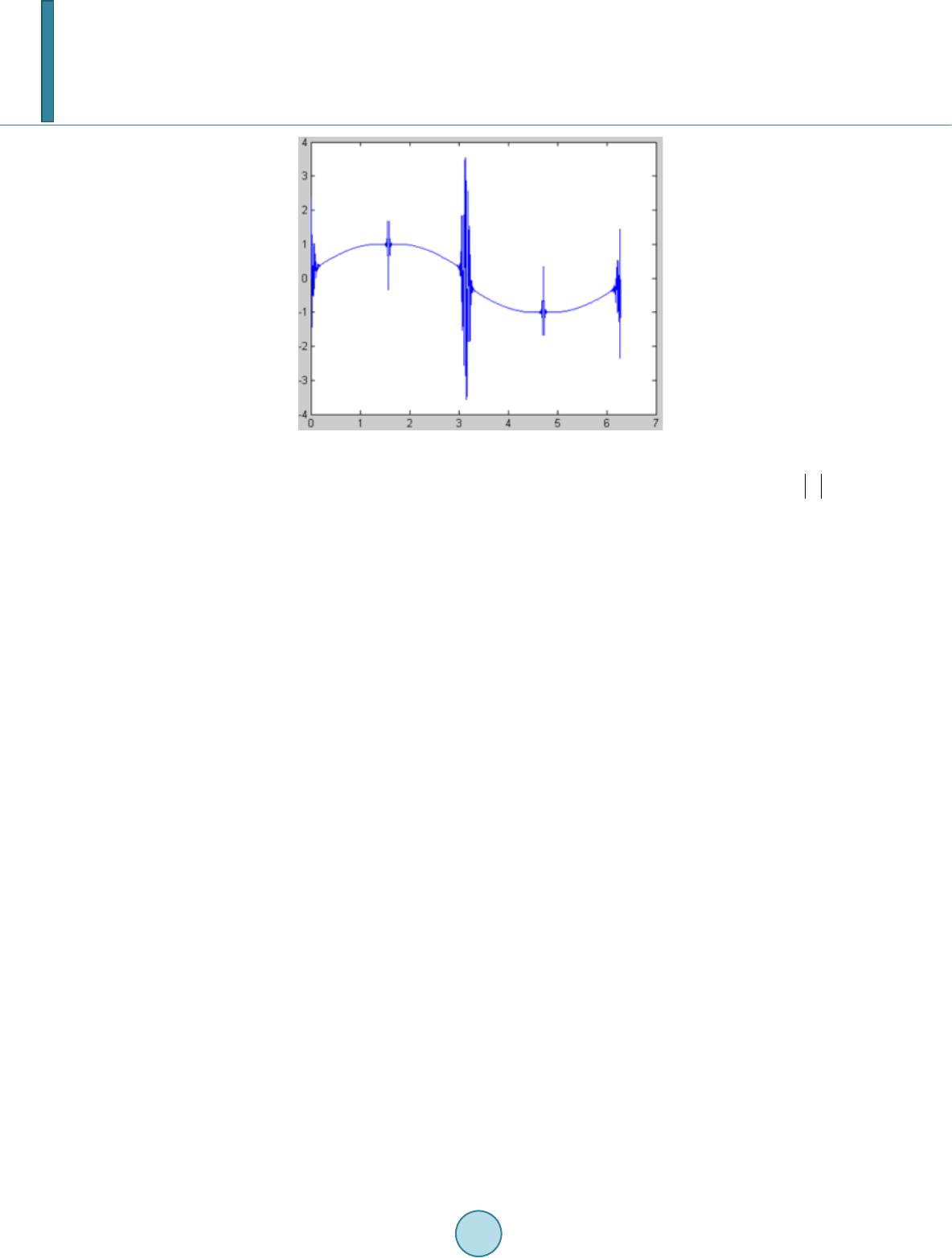 L.-R. Dung et al. Figure 3. Divergen t result of shock process. certainly be zero. Moreover, if the gradient is too large, the min mode of semi-discrete model will let to be the smaller value. In Table 1, we can the improvement of weight generation. According to [8], there are three main features of shock filter. Firstly, the segments of image is separated at the edge. Secondly, the local extrema are unchanged, and none of new local extrema are created. Thirdly, the Final result is constant. 2.3. Two-Stage Shock Filter Design A shock filter design includes two parts, the diffusion part and the shock part. In the general design, the shock filter is a one-stage design, shown in Figure 4, because the parameters of diffusion part and the shock part are same. The one-stage design saves the time of calculating parameters, but processing the diffusion and the shock at the same time can’t remove all noise. Therefore, we design a two-stage shock filter, shown in Figure 5, to improve the problem. At the first stage, we execute the diffusion part to remove all noise. Then, we execute the shock part at the second stage. However, we get a better result, shown in Figure 6, by using two-stage design. 3. Simulation and Verification 3.1. Noise Removal in X-Ray Image In the simulation of removing noise, we use the traditional median filter and the diffusio n algorithm proposed by this paper to compare the results. Two types of noise that we add to the noise-free “hand” X-ray image are Gaussian noise (variance = 0.01) and impulse noise (corrupting 30% of image), and are common in the X-ray image. The results are shown in Figure 7. The verification’s method is computing the peak signal-to-noise ratio (PSNR) and structural similarity (SSIM) with the restorative image and the noise-free image. Then, the value of PSNR and SSIM is shown in Table 2. Figure 7 shows that diffusion filter can remove much more noise than median filter. Table 2 shows that dif- fusion filter is obviously better than median filter. 3.2. Segmentation and Edge Enhancement in X-Ray Image In the simulation of segmentation and edge enhancement, we apply a Gaussian blur to the “brain” X-ray image, and we process the blurred image with the shock filter. The results are shown in Figure 8, and the histograms of images are shown in Figure 9. As shown in Figure 8, it can be observed that the perform-ance of edge enhancement is great. Figure 9 shows the blurred image is separated into 3 regions. Then, we compare the performance with Lucy-Richardson deconvolution (L-R). L-R is a popular deblurring 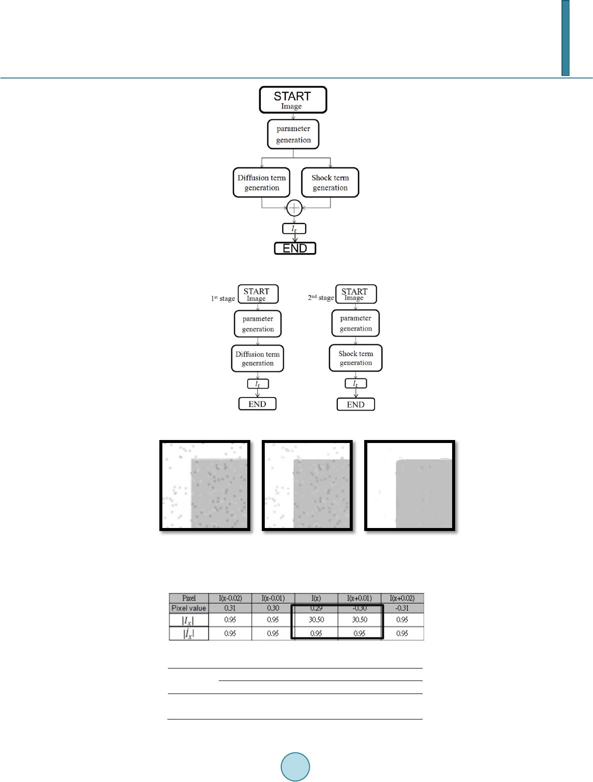 L.-R. Dung et al. Figure 4. Follow chart of one-stage shock filter design. Figure 5. Follow chart of two-stage shock filter design. (a) (b) (c) Figure 6. Results of different stage design. (a) Noisy image; (b) One-stage process; (c) T wo-stage process. Table 1. Comparisons of weight generation. Table 2. Comparisons of restorative result. PSNR S SIM PSNR S S IM 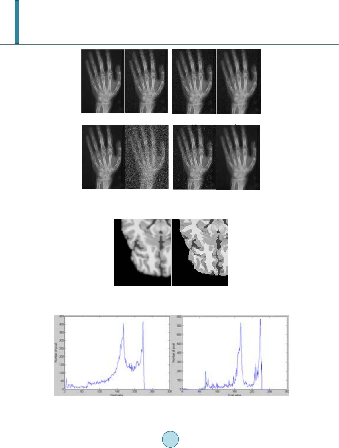 L.-R. Dung et al. (a) (b) (c) (d) (a) (b) (c) (d) Figure 7. Results of removing noise. Left: Gaussian noise. Right: impulse noise. (a) Noise- free image; (b) Noisy image; (c)Median filter; (d) Diffusion filter. (a) (b) Figure 8. Results of shock process. (a) Blurred image; (b) En- hanced image. (a) (b) Figure 9. Histograms of images. (a) Blurred image; (b) Enhanced image. 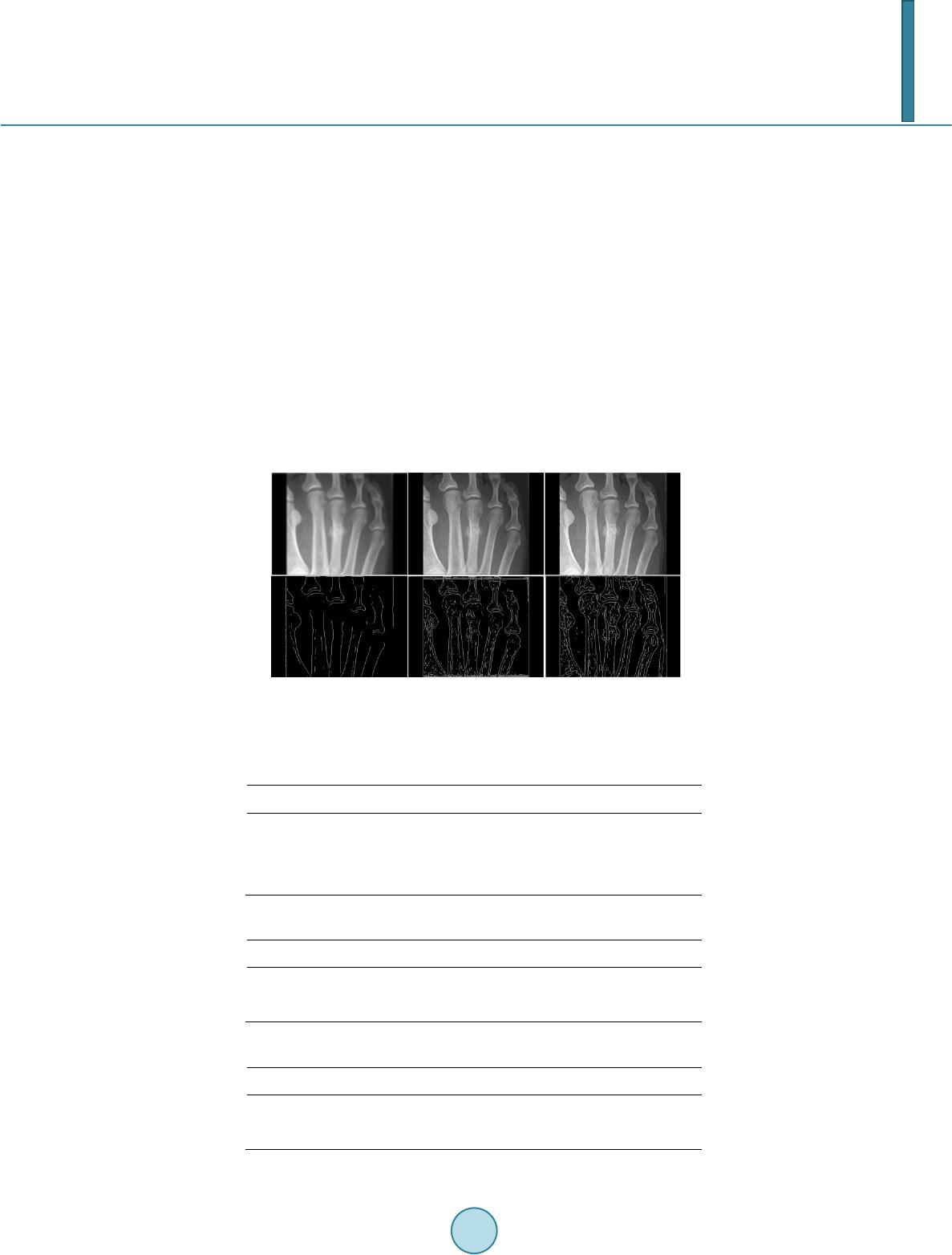 L.-R. Dung et al. method to enhance blurred edge. In the simulation, we assume that the point spread function (PSF) used by L-R is estimated perfectly. The results are shown in Figure 10. The edges are detected by Sobel filter. As shown in Figure 10, the edge detection of shock result is better than L-R result. The processing time of shock filter is 5 times shorter than L-R. The performance of shock filter is better than L-R. 4. Hardware Architecture In hardware implementation, the architecture of shock filter is shown in Figure 11. The architecture of image’s data FIFO is a 2-SRAM Ping-Pong buffer architecture, shown in Figure 12. Table 3 shows the performance of implementation in FPGA. We use the look-up table (LUT) to replace the divider. The reason is that lots of denominators aren’t used. The synthesis result is compared to the divider of intellectual property core (IP-core), shown in Table 4. Furthermore, we use the Booth-Folding (B-F) technique [ 9] to implement the squarer. The synthesis result is compared to the squarer and multiplier of intellectual property core (IP-core), shown in Table 5. The size of X-ray HD images which we use are 944 × 1276 pixels (944 p), and the number of iterations is 12. The processing time of each frame is 121 ms. To achieve the real time processing specification (30 frame/s), we use the four-series hardware architecture, shown in Figure 13. (a) (b) (c) Figure 10. Comparison of edge enhancement result. (a) Blurred image; (b) L-R result; (c) Shock result. Table 3. Performance of implementation. Shock filter Board used Cyclone IV Area 987 logic elements Cycle 10 ns Table 4. Comparisons of synthesis result. IP-co re LUT Area 1444 gates 766 gates Cycle 2.75 ns 2.55 ns Table 5. Comparisons of synthesis result. Mu ltip lier Sq uarer B-F Area 703 gates 545 gates 4 10 gates Cycle 3 ns 2.14 ns 2.14 ns 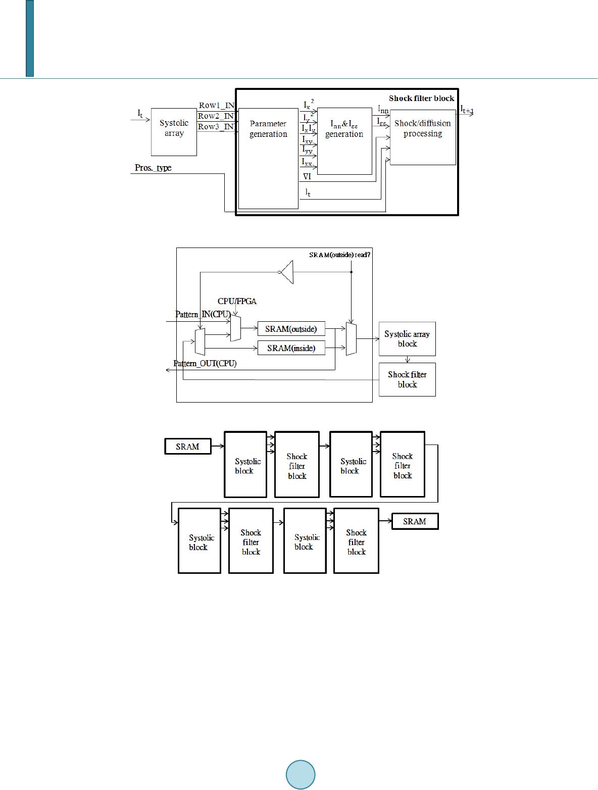 L.-R. Dung et al. Figure 11. Architecture diagram of shock filter. Figure 12. Architecture diagram of pattern FIFO. Figure 13. Four -series hardware architecture. We spend most time writing and reading dates from SRAM when we process the image. Therefore, we use the four-series hardware design to reduce the frequency of writing and reading dates. The processing time of each frame is reduced by 75 percent. 5. Conclusion In this paper, we propose a restoration method of X-ray image by using the shock filter. The performances of removing noise show that the method is much better than median filter, and that the value of PSNR and SSIM is very high in any types of noise. The performances of segmentation and edge enhancement also show that the method is applicable to restore the corrupted X-ray image. In the hardware implementation, the VLSI architec- ture is very low hardware cost and can achieve the real time processing specification (30 frame/s).  L.-R. Dung et al. References [1] V acavant, A. (2012) Fast Smoothed Shock Filtering. IEEE International Conference on Pattern Recognition (ICPR). [2] Osher, S.J. and Rudin, L.I. (1990) Featu re-Oriented Image Enhancement Using Shock Filters. SIAM Journal on Nu- merical Analysis, 27, 919-940. http://dx.doi.org/10.1137/0727053 [3] Alvarez, L. and Mazorra, L. (1994) Signal and Image Restoration Using Shock Filters and Anistropic Diffusion. SIAM Journal on Numerical Analysis, 31, 59 0-605. http://dx.doi.org/10.1137/0731032 [4] Weicker t, J. (1998) Anisotropic Diffusion in Image Processing. Teubner Verlag, Stuttgart. [5] Derich e, R. and Faugeras, O. (1996) Les EDP en Traitement des Images et Vision par Ordinateur. Institut National de Recherche en Informatique et en Automatique, 13. [6] Tschu mperle, D. and Deriche, R. (2002) Diffusion PDE’s on Vector-Valued Images. IEEE Signal Processing Maga- zine, 19 , 16-25. http://dx.doi.org/10.1109/MSP.2002.1028349 [7] Wel k, M., Weickert, J. and Galic, I. (2007) Theoretical Foundations for Spatially Discrete 1-D Shock Filtering. Image and Vision Computing, 25, 455-463. http://dx.doi.org/10.1016/j.imavis.2006.06.001 [8] Gilboa, G., Sochen, N.A. and Zeevi, Y.Y. (2002 ) Regularized Shock Filters and Complex Diffusion. Computer Vi- sion—E C CV , 399-413. [9] Antonio, S., Napoli, E. and Caro, D.D. (2001) New Design of Squarer Circuits Using Booth Encoding and Folding Techniques. IEEE International Conference on Electronics, Circuits and Systems, 193-196.
|