 Journal of Computer and Communications, 2014, 2, 9-17 Published Online November 2014 in SciRes. http://www.scirp.org/journal/jcc http://dx.doi.org/10.4236/jcc.2014.213002 How to cite this paper: Ge, C., Wu, J.H. and Tang, Y.M. (2014) Ultrasound Driving Application of a Universal Waveform Generator Derived from Displaying Driving System. Journal of Computer and Communications, 2, 9-17. http://dx.doi.org/10.4236/jcc.2014.213002 Ultrasound Driving Application of a Universal Waveform Generator Derived from Displaying Driving System Chang Ge1, Jihui Wu2, Yongming Tang2 1Department of Electrical and Computer Engin eering, University of Alberta, Edmonton, Canada 2School of Electronic Science and Engineering, Southeast University, Nanjing, China Email: cge@ual berta.ca Received 9 August 2014 Abstract The design of a universal waveform generator derived from displaying driving applications using floating power and Miller integrator circuit is introduced first. Then, the feasibility of driving ul- trasound transducers is verified by the test of the circuit and compared with other specific design of pulse generator for ultrasound driving purpose. Keywords Universal Waveform Generator, Ultrasound , Pulse, Miller Integrator Circuit 1. Introduction Piezoelectric ultrasound transducers are used for a various kinds of applications. The popularity of piezoelectric ultrasound transducer comes from its high controllability. In general, piezoelectric ultrasound transducer has a structure like the one shown in Figure 1 [1]. To get expected ultrasound output frequency ranging from 60 KHz to as high as 60 MHz, only the thickness of piezoelectric layer and matching layer need adjustment. For ultra- sound transducer driving, an alternative power supply need is generally applied on the electrodes. The effective driving of piezoelectric ultrasound transducers depends on the high amplitude pulse. In common applications like ultrasound detection, surgical ultrasound and ultrasound chemistry, the requirement for high amplitude is due to the fact that attenuation of ultrasound will cause loss of information contained in the reflec- tion wave in a pulse-echo detection system or reduce the power of ultrasound induced effect. In practical circuits, the high amplitude ultrasound pulses can be implemented either in unipolar form or in bipolar form [2]-[5]. Un- ipolar form has the advantage of shorter wave length, i.e. hi gher frequency. Bipolar form can get to the high amplitude with lower unwanted DC current and leakage. Regardless of the type of pulse wave generated, different kinds of ultrasound driving pulse generator circuit have many characters in common, wi t h the biggest one being the using of high speed high voltage MOSFET and corresponding driving structure at gate electrode. At present days, the research works about the ultrasound pulse generators focus on three aspects, they are the pulse generator for higher frequency [3]-[5], pulse generator for lower cost [2], multifunction and reconfigurable pulse generators [5], respectively. 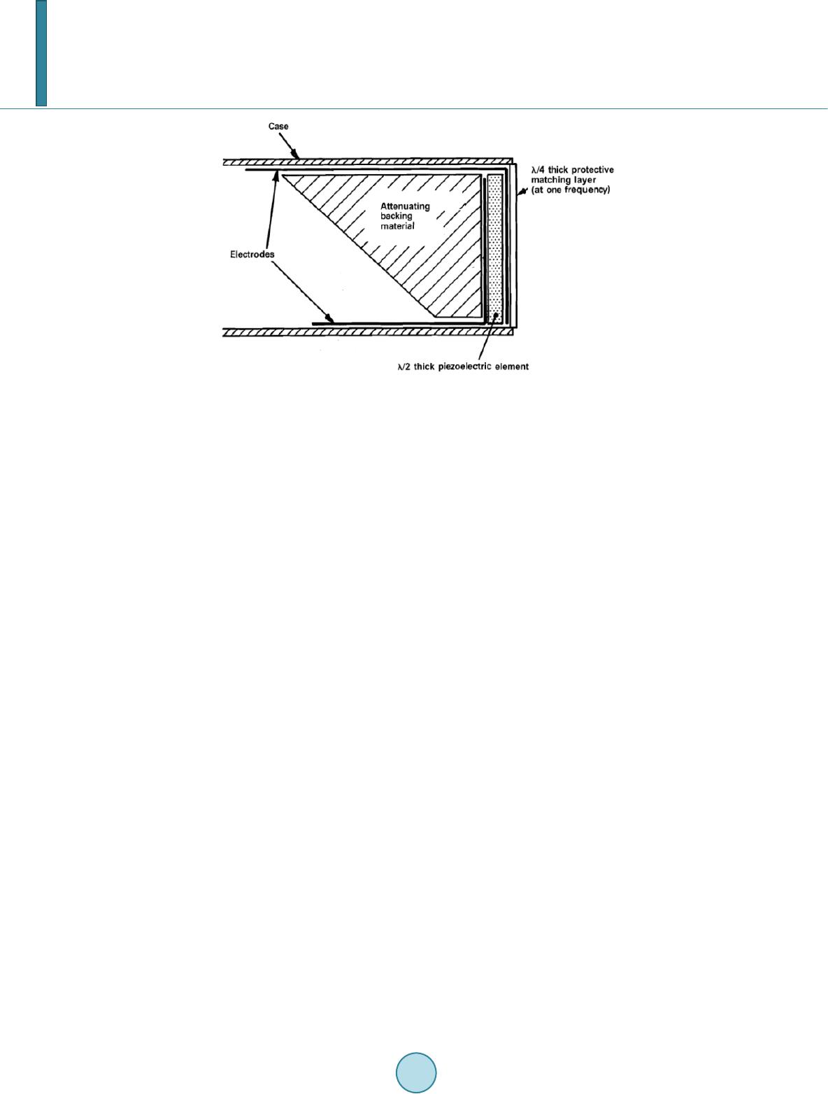 C. Ge et al. Figure 1. Generic structure of a piezoelectric ultrasound transducer [1]. As we know, many other electrical devices need high voltage pulses for controllable driving, such as display- ing device. Similar to the driving circuit of an ultrasound transducer, the displaying driving circuit also depends on the MOSFETs for pulse generation. The frequency for displaying and ultrasound driving overlaps a lot as well . Moreover, as the scale of displaying devices significantly reducing, the difference of circuit size between displaying and ultrasound driving is becoming smaller. There is also a trend of low cost, versatile design in the displaying driving applications. Therefore, it is possible for the displaying driving circuit being applied to ultra- sound driving directly or after tiny modification. In this paper, the design of a universal waveform generator derived from displaying driving system is de- scribed, followed by corresponding test, with a result showing that the generator is capable of generating wave- form satisfying requirement of ultrasound driving on amplitudes. Then comparisons with typical ultrasound driving pulse generators are carried out in order to verify the possibility of using the universal waveform gene- rator for ultrasound driving. Last but not least, a conclusion based on comparisons is provided in together with brief description of future work. 2. Design of Universal Waveform Generating Circuit 2.1. Circuit Function The circuit designed here has put an emphasis on generating multiple kinds of waves that can fulfill the re- quirement of multiple ap plica tions. Thus, the high-voltage driving circuit should be able to generate integral wave, triangle wave, square wave, positive and negative pulses and achieve rapid transitions and slope changes between different voltage within a wide range of input signal frequency. Since different displaying driving sys- tems also have different requirement on pulse amplitude, in some cases, multiple positive and negative voltage levels are expected. The universal waveform generator should be able to reach at least five different voltage lev- el, an analog zero, two positive level and two negative level. Therefore, seven modules should be included in the driving system, respectively, to achieve rapid transitions and changes with slope between positive and negative voltage levels as well as the analog zero, i.e. the function to ramp down to-VSUS, jump down to-VSUS, ramp down to-VPP, jump down to-VPP, jump to GND, jump to + VSUS, and ramps up to + VSETUP. Here, the voltage levels involved has a relationship in size as: +VSETUP> +VSUS> 0> -VPP > -VSUS The schematic block diagram is shown as Fig ure 2. In order to implement certain waveforms, taking a unipolar negative pulse ramping down with slope to-VSUS as an example, first the RAMP_DN_-VSUS module works, to pull the voltage of the output line from zero to-VSUS with a slope. Then the GND module works to lift the voltage of output line back to zero. As a result, a negative pulse to -VSUS with a slope is generated. For other pulse, the generation is similar to the negative pulse. The frequency of the pulse depends on the control signal frequency and the frequency limitation of devices. 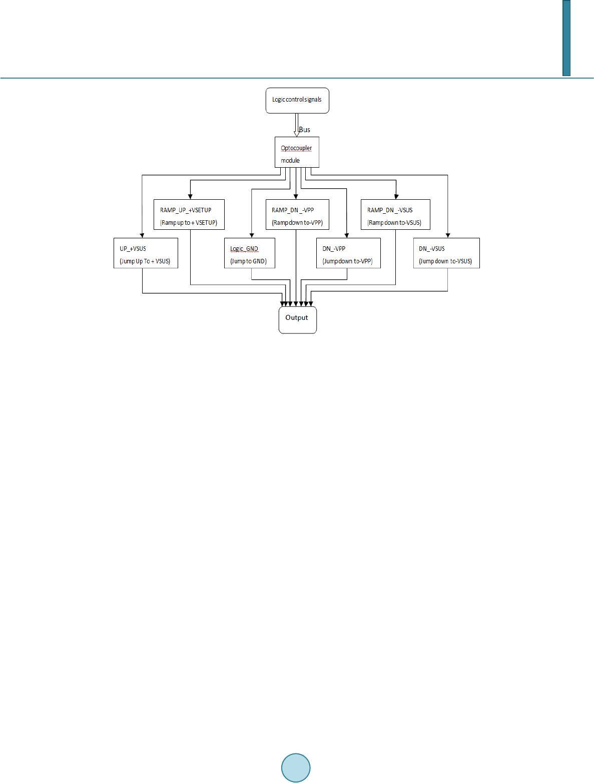 C. Ge et al. Fig ure 2. The schematic block diagram of the circuit design. As for the logic control signals, since the seven modules are in parallel, the control signal is at least 7-bit-long signal with each bit control one module. Assume that the left most controls the Ramp_Dn_-VSUS module and the right most controls the GND module. Then, to implement the waveform mentioned in previous Section 2.1, a series of “1000000” and “0000001” is required. 2.2. Circuit Design The seven modules in the universal waveform generator are implemented using similar structure. Take the RAMP_DN_-VSUS module as an example, which is shown in F igure 3. Besides the logic control modules and output line, an optocoupler module, a push-pull circuit driving the pulse generator circuit and an isolation mod- ule is included. For the pulse generating circuit, here a Miller integrating circuit with MOSFET is used for vol- tage level ramping down with slope. The miller integrator circuit has a potentiometer at the gate electrode of MOSFET. The slope of the waveform when ramping down to -VSUS can be adjusted by adjusting the potenti- ometer. The circuit implementation of the Miller integrating circuit is shown in Figure 4(a). For voltage ‘jumping’ part in every module, a common MOSFET driving structure is used, like those in [2 ]-[5]. All pulse generating modules use the same type of N-MOSFET . Another unique character of the universal waveform generator designed here is the usage of a floating power supply implemented by an ASIC chip DMCD 15S15-200. By using the floating power to drive related chips, the waveform generator can implement bipolar waveforms using only N-MOSFET, each of which is responsible for one kind of voltage change. This design strategy contributes greatly to making the pulse generated more sym- metric in rising and falling time. A peripheral design for DMCD 15S15-200 is shown in Figure 4(b). Each of the seven modules mentioned has a similar DMCD 15S15-200 circuit like Figure 4(b) to provide power supply. Figure 5 is the picture of the PCB circuit board for the universal waveform generator. Here a two-layer PCB board is fabricated. 3. Testing Results Test results of the circuit are shown in Figure 6. In the tests, the output of the universal waveform generator is directly connected to Angilent DSO7034B oscilloscope. Clearly, the result shows that the universal waveform generator can generates ramping up and ramping down waves with the amplitude of 300 V and bipolar pulse 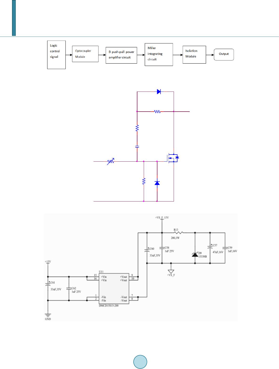 C. Ge et al. Figure 3. The block diagram of ramp_DN_VSUS module. (a) (b) Figure 4. Characteristic structure of the waveform generator desig ned : (a) The Miller integrating circuit; (b) The floating power supply using DMCD15S15-200. R3 100k C1 1n R1 1k U1 R2 1k D1 VR 1 100k D2 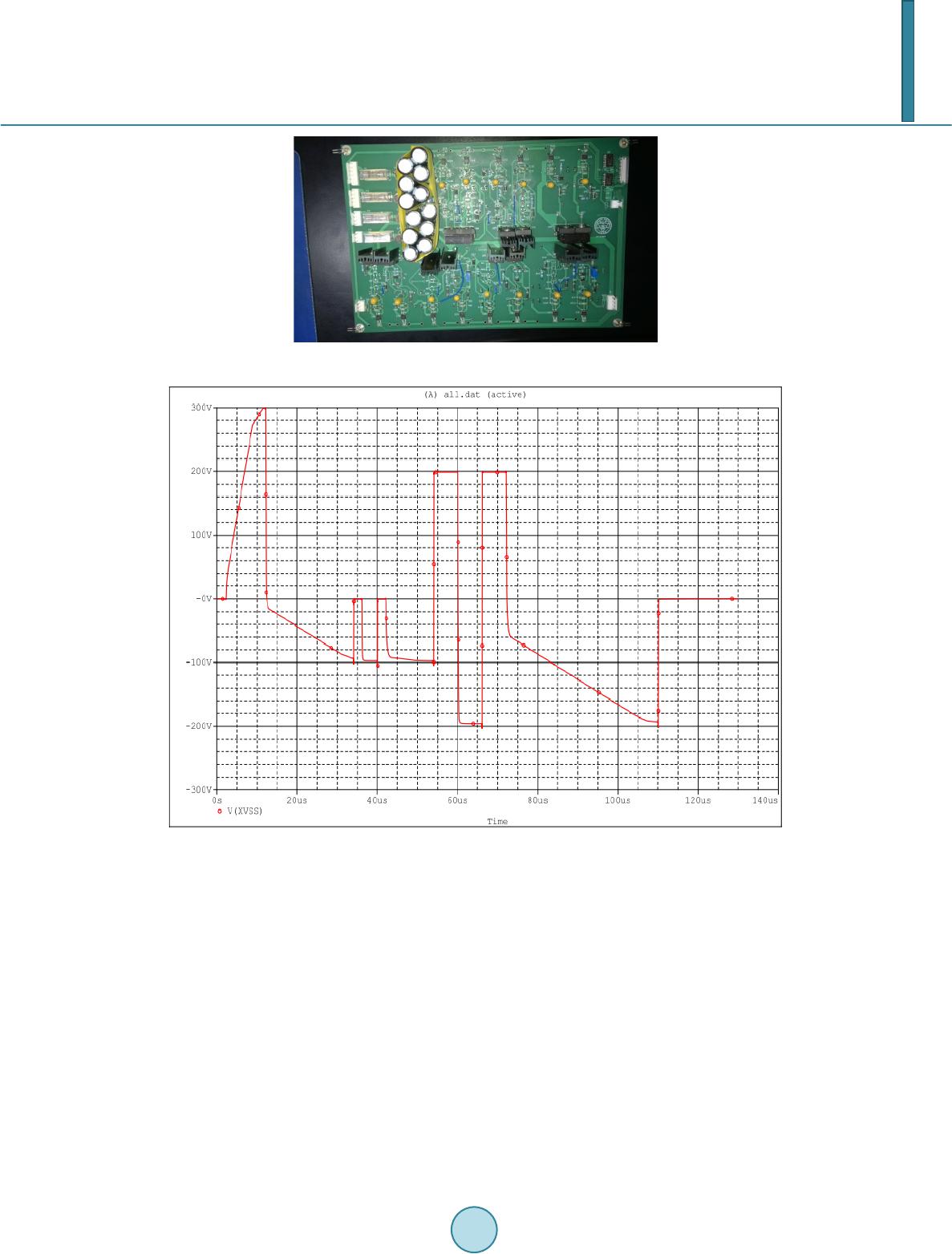 C. Ge et al. Figure 5. PCB board fabricated of desi gned circuit. Figure 6. Testing wave of the des ign ed circuit. with a peak-to-peak voltage of 400 V. For the frequency, the test frequency is 100 KHz for both the bipolar pulse and ramping pulse. The maximum frequency for the prototype can be 330 KHz. Figure 7 provides a comparison of waveforms generated by the universal waveform generator, and circuit specifically designed for ultrasound driving in [2]-[5]. Through the comparison, the amplitude of waveform, both unipolar and bipolar, generated by the universal waveform generator is proved to satisfy the requirement for ultrasound transducer driving. Most of the output in Figure 7 has a specific frequency response spectrum. This is not reflected in the test of the universal waveform generator. The explanation for this is provided later. Also, the frequency of the waveform in [2]-[5] is higher. This is because they aim at high frequency ultra- sound (HFUS) applications, which is an emerging application of ultrasound over 20 MHz. Besides these high frequency applications, there are still many commercial ultrasound applications at much lower frequency, such as some of the B-mode scanning and non-destructive detection transducers [6]. Regardless of the frequency, as mentioned previously, to ensure certain resolution or power of the effect induced, pulse with the relatively high amplitude of over 100 V is always expected. The frequency is of great importance, the amplitude plays a more signi fi ca nt role in verification of feasibility to drive ultrasound transducers for a given circuit.  C. Ge et al. (a) (b) (c)  C. Ge et al. (d) (e) (f) Figure 7. Outputs of pulse generators involved in this Paper: (a) Circuit designed in this pa- per; (b) Output in [2]; (c) Output in [3]; ((d), (e)) Unipolar and bipolar output in [4]; (f) Bi- polar output in [5].  C. Ge et al. 4. Comparison with Circuit Designed for Ultrasound Driving The comparison of amplitude and discussions for frequency of waveform generated has been provided in pre- vious part. Here the discussion mainly focuses on the comparison of other factors. As for the controlling digital signals, compared with [5], which implements bipolar pulses generation, the universal waveform generator de- signed here doesn’t need the complicated controlling signals as the one in [5]. The design in [5] uses a PMOS and NMOS pair. Due to the difference in mobility of holes and electrons, switching time of the PMOS and NMOS is not different, therefore, control signal for NMOS and PMOS need to be designed respectively. The difference also leads to asymmetry in rising and falling times [5]. For the waveform generator designed in this paper, there are no such problems since the ASIC chip DMCD15S15-200 is used to provide floating power and only N-MOSFETs of same type are used. A multifunction and reconfigurable pulse generator for ultrasound driving was introduced in [4]. It can gener- ate unipolar waves, bipolar waves as well as arbitrary waves. The unipolar wave has the higher amplitude, simi- lar result is got in the waveform generator designed here. However, the unipolar and bipolar pulse generator part are separated part as shown in Figure 8 [4]. For the universal waveform generator designed in this paper, un- ipolar pulse generation only uses part of the bipolar pulse generation circuit. The only difference is in the control signals. This reduction on circuit complexity make the circuit designed in this paper easier to maintain and de- bug, while provides similar waveform output. Generally, in the ultrasound driving system, the matching network is used for damping unwanted waveforms at other frequencies and maximizing the power efficiency. In the references [2]-[5], the matching network leads to the damping curves shown in Figure 7. Since its origin is displaying driving circuit, the universal waveform generator designed in this paper doesn’t have such a matching network. However, the network is between the pulse generator and transducer, i.e. a component outside the driving pulse generator. So, the missing of matching network in the universal waveform generator doesn’t affect its application in ultrasound transducer driving. Figure 8. PCB board provided in [4].  C. Ge et al. 5. Summary Through test and comparison, it can be found that the universal waveform generator designed in this paper has an output amplitude similar or even larger to the ultrasound driving pulse generators [2]-[5]. Using N-MOSFET for pulse generation only, the circuit alleviates the problem of asymmetry in bipolar waveforms. Together with a driving ability designed for displaying applications, which is powerful enough to drive ultrasound transducers, the waveform generator designed in this paper is believed to be able to driving ultrasound transducer and gener- ate ultrasound wave with expected intensity for various applications. In detail, the waveform generator can be used as a reconfigurable pulse generator. To fully put the universal waveform generator into ultrasound driving application, further work includes the supplement of matching network and removal of some modules unrelated to ultrasound driving as a consideration of cost. Moreover, as high frequency ultrasound applications are be- coming more and more popular, substitution of some devices to faster ones is expected in order to implement high frequency applications. References [1] P re ston , R.C. (1991) Output Measurements for Medical Ultrasound. Springer, Berlin. http://dx.doi.org/10.1007/978-1-4471-1883 -1 [2] Brown, J.A. and Lockwood, G.R. (2002) A Lo w-Cost, High-Performance Pulse Generator for Ultrasound Imaging. IEEE Transactions on Ultrasonics, Ferroelectrics, and Frequency Control, 49, 848-851. http://dx.doi.org/10.1109/TUFFC.2002.1009345 [3] Wu, J.-X., Du, Y.-C., Lin, C.-H., Chen, P.-J. and Chen, T.S. (2013) A Novel Bipolar Pulse Generator for High -Fre- quency Ultrasound System. 2013 IEEE International Ultrasonics Symposium (IUS) [Serial Online], 1571. http://dx.doi.org/10.1109/ULTSYM.2013.0400 [4] Qiu , W.B., Yu, Y.Y., Ts an g , F.K. and S un , L. (2012) A Multifunctional, Reconfigurable Pulse Generator for High- Frequency Ultrasound Imaging. IEEE Transactions on Ultrasonics, Ferro electri cs and F requ ency Control, 59 , 1558- 1567. http://dx.doi.org/10.1109/TUFFC.2012.2355 [5] X u, X.C., Yen, J.T. and Shung, K.K. (2007 ) A Low-Cost Bipolar Pulse Generator for High -Frequency Ultrasound Ap- plications. IEEE Transactions on Ultrason ics, Ferroelect rics and Frequen cy Control, 54, 443-447. http://dx.doi.org/10.1109/TUFFC.2007.259 [6] Ch eeke, J.D.N. (2012) Fundamental s and Applications of Ultrasonic Waves. CRC P ress, Boca Raton. http://dx.doi.org/10.1201/b12260
|