Paper Menu >>
Journal Menu >>
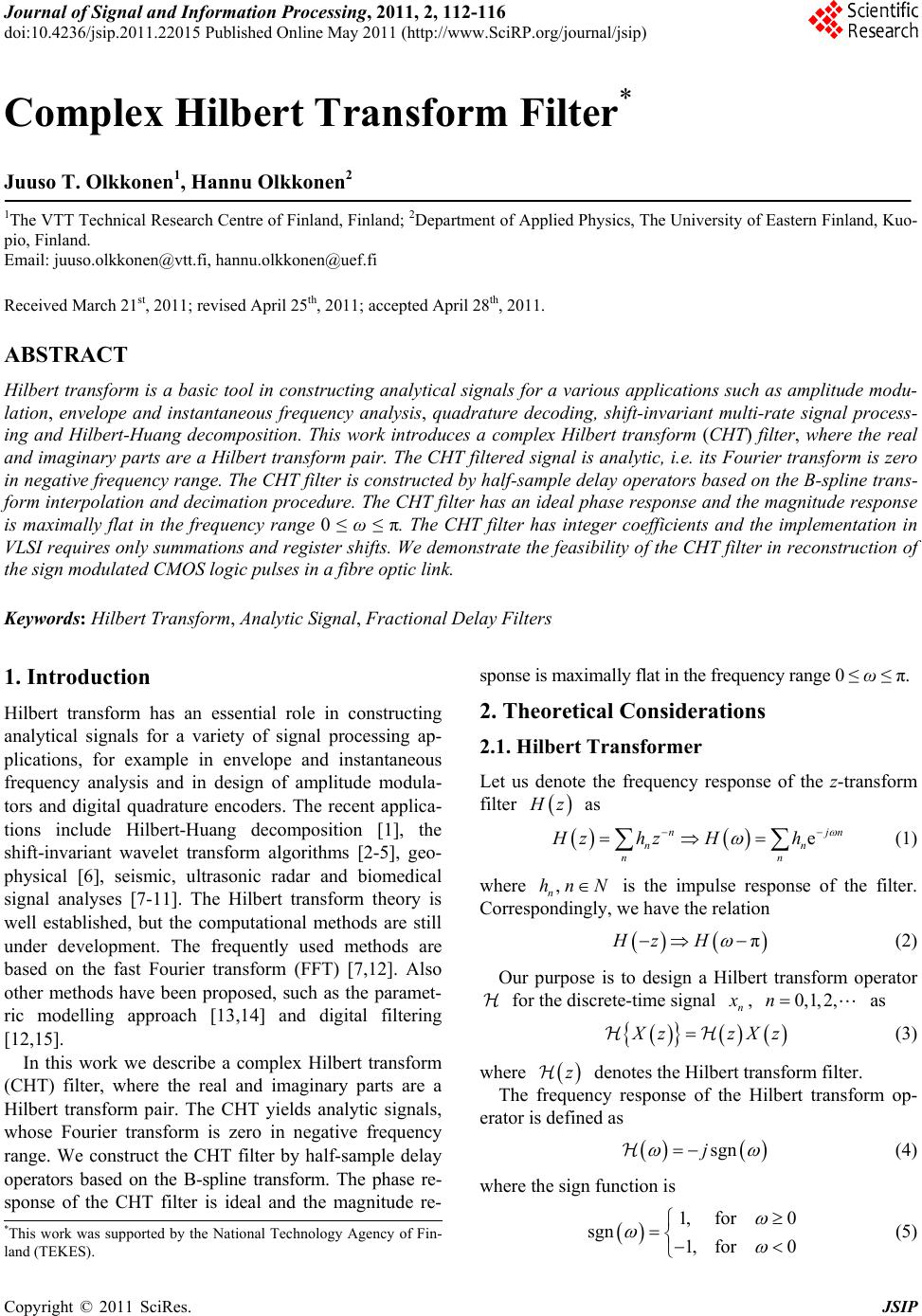 Journal of Signal and Information Processing, 2011, 2, 112-116 doi:10.4236/jsip.2011.22015 Published Online May 2011 (http://www.SciRP.org/journal/jsip) Copyright © 2011 SciRes. JSIP Complex Hilbert Transform Filter* Juuso T. Olkkonen1, Hannu Olkkonen2 1The VTT Technical Research Centre of Finland, Finland; 2Department of Applied Physics, The University of Eastern Finland, Kuo- pio, Finland. Email: juuso.olkkonen@vtt.fi, hannu.olkkonen@uef.fi Received March 21st, 2011; revised April 25th, 2011; accepted April 28th, 2011. ABSTRACT Hilbert transform is a basic tool in constructing analytical signals for a various applications such as amplitude modu- lation, envelope and instantaneous frequency analysis, quadrature decoding, shift-invariant multi-rate signal process- ing and Hilbert-Huang decomposition. This work introduces a complex Hilbert transform (CHT) filter, where the real and imaginary parts are a Hilbert transform pair. The CHT filtered signal is analytic, i.e. its Fourier transform is zero in negative frequency range. The CHT filter is constructed by half-sample delay operators based on the B-spline trans- form interpolation and decimation procedure. The CHT filter has an ideal phase response and the magnitude response is maximally flat in the frequency range 0 ≤ ω ≤ π. The CHT filter has integer coefficients and the implementation in VLSI requires only summations and register shifts. We demonstrate the feasibility of the CHT filter in reconstruction of the sign modulated CMOS logic pulses in a fibre optic link. Keywords: Hilbert Transform, Analytic Signal, Fractional Delay Filters 1. Introduction Hilbert transform has an essential role in constructing analytical signals for a variety of signal processing ap- plications, for example in envelope and instantaneous frequency analysis and in design of amplitude modula- tors and digital quadrature encoders. The recent applica- tions include Hilbert-Huang decomposition [1], the shift-invariant wavelet transform algorithms [2-5], geo- physical [6], seismic, ultrasonic radar and biomedical signal analyses [7-11]. The Hilbert transform theory is well established, but the computational methods are still under development. The frequently used methods are based on the fast Fourier transform (FFT) [7,12]. Also other methods have been proposed, such as the paramet- ric modelling approach [13,14] and digital filtering [12,15]. In this work we describe a complex Hilbert transform (CHT) filter, where the real and imaginary parts are a Hilbert transform pair. The CHT yields analytic signals, whose Fourier transform is zero in negative frequency range. We construct the CHT filter by half-sample delay operators based on the B-spline transform. The phase re- sponse of the CHT filter is ideal and the magnitude re- sponse is maximally flat in the frequency range 0 ≤ ω ≤ π. 2. Theoretical Considerations 2.1. Hilbert Transformer Let us denote the frequency response of the z-transform filter H z as e njn nn nn Hzhz Hh (1) where , n hn N is the impulse response of the filter. Correspondingly, we have the relation πHz H (2) Our purpose is to design a Hilbert transform operator for the discrete-time signal n x , 0,1, 2,n as X zzXz (3) where z denotes the Hilbert transform filter. The frequency response of the Hilbert transform op- erator is defined as sgnj (4) where the sign function is 1, for0 sgn 1, for0 (5) *This work was supported by the National Technology Agency of Fin- land (TEKES). 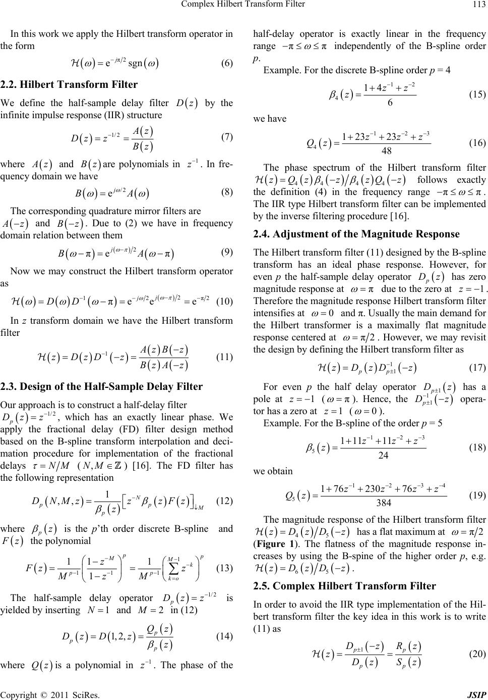 Complex Hilbert Transform Filter Copyright © 2011 SciRes. JSIP 113 In this work we apply the Hilbert transform operator in the form π2 esgn j (6) 2.2. Hilbert Transform Filter We define the half-sample delay filter Dz by the infinite impulse response (IIR) structure 1/ 2 A z Dz zBz (7) where A z and Bzare polynomials in 1 z . In fre- quency domain we have /2 ej BA (8) The corresponding quadrature mirror filters are A z and Bz. Due to (2) we have in frequency domain relation between them 2 πeπ j BA (9) Now we may construct the Hilbert transform operator as 2 12π2 πee e j j DD (10) In z transform domain we have the Hilbert transform filter 1 A zB z zDzD zBzAz (11) 2.3. Design of the Half-Sample Delay Filter Our approach is to construct a half-delay filter 1/2 p Dz z , which has an exactly linear phase. We apply the fractional delay (FD) filter design method based on the B-spline transform interpolation and deci- mation procedure for implementation of the fractional delays NM (,NM) [16]. The FD filter has the following representation 1 ,, N pp M p DNMzz zFz z (12) where pz is the p’th order discrete B-spline and F z the polynomial 1 11 1 11 1 1 p p MMk pp ko z Fz z MzM (13) The half-sample delay operator 1/2 p Dz z is yielded by inserting 1N and 2 M in (12) 1, 2,p p p Qz Dz Dzz (14) where Qzis a polynomial in 1 z. The phase of the half-delay operator is exactly linear in the frequency range ππ independently of the B-spline order p. Example. For the discrete B-spline order p = 4 12 4 14 6 zz z (15) we have 123 4 12323 48 zzz Qz (16) The phase spectrum of the Hilbert transform filter 44 44 zQzzzQz follows exactly the definition (4) in the frequency range ππ . The IIR type Hilbert transform filter can be implemented by the inverse filtering procedure [16]. 2.4. Adjustment of the Magnitude Response The Hilbert transform filter (11) designed by the B-spline transform has an ideal phase response. However, for even p the half-sample delay operator p Dz has zero magnitude response at π due to the zero at 1z . Therefore the magnitude response Hilbert transform filter intensifies at 0 and π. Usually the main demand for the Hilbert transformer is a maximally flat magnitude response centered at π2 . However, we may revisit the design by defining the Hilbert transform filter as 1 1 pp zDzD z (17) For even p the half delay operator 1p Dz has a pole at 1z (π ). Hence, the 1 1 p Dz opera- tor has a zero at 1z (0 ). Example. For the B-spline of the order p = 5 123 5 111 11 24 zzz z (18) we obtain 1234 5 1 7623076 384 zzzz Qz (19) The magnitude response of the Hilbert transform filter 45 zDzDz has a flat maximum at π2 (Figure 1). The flatness of the magnitude response in- creases by using the B-spine of the higher order p, e.g. 65 zDzDz . 2.5. Complex Hilbert Transform Filter In order to avoid the IIR type implementation of the Hil- bert transform filter the key idea in this work is to write (11) as 1pp pp DzRz zDz Sz (20) 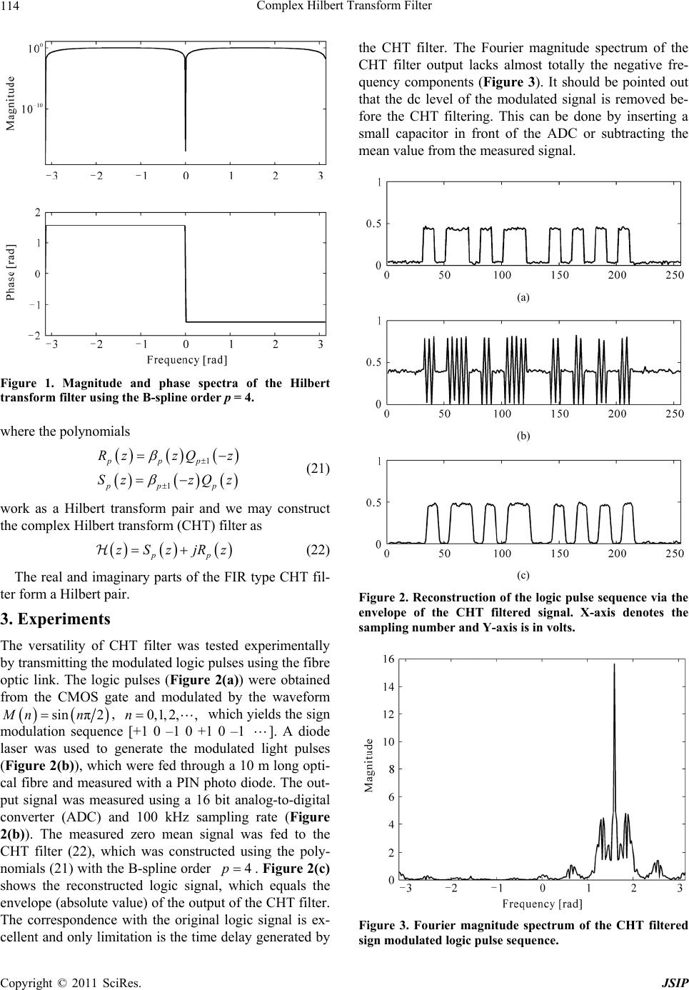 Complex Hilbert Transform Filter Copyright © 2011 SciRes. JSIP 114 Figure 1. Magnitude and phase spectra of the Hilbert transform filter using the B-spline order p = 4. where the polynomials 1 1 ppp pp p RzzQz Sz zQz (21) work as a Hilbert transform pair and we may construct the complex Hilbert transform (CHT) filter as pp zSzjRz (22) The real and imaginary parts of the FIR type CHT fil- ter form a Hilbert pair. 3. Experiments The versatility of CHT filter was tested experimentally by transmitting the modulated logic pulses using the fibre optic link. The logic pulses (Figure 2(a)) were obtained from the CMOS gate and modulated by the waveform sin π2Mn n, 0,1, 2,,n which yields the sign modulation sequence [+1 0 –1 0 +1 0 –1 ]. A diode laser was used to generate the modulated light pulses (Figure 2(b)), which were fed through a 10 m long opti- cal fibre and measured with a PIN photo diode. The out- put signal was measured using a 16 bit analog-to-digital converter (ADC) and 100 kHz sampling rate (Figure 2(b)). The measured zero mean signal was fed to the CHT filter (22), which was constructed using the poly- nomials (21) with the B-spline order 4p. Figure 2(c) shows the reconstructed logic signal, which equals the envelope (absolute value) of the output of the CHT filter. The correspondence with the original logic signal is ex- cellent and only limitation is the time delay generated by the CHT filter. The Fourier magnitude spectrum of the CHT filter output lacks almost totally the negative fre- quency components (Figure 3). It should be pointed out that the dc level of the modulated signal is removed be- fore the CHT filtering. This can be done by inserting a small capacitor in front of the ADC or subtracting the mean value from the measured signal. (a) (b) (c) Figure 2. Reconstruction of the logic pulse sequence via the envelope of the CHT filtered signal. X-axis denotes the sampling number and Y-axis is in volts. Figure 3. Fourier magnitude spectrum of the CHT filtered sign modulated logic pulse sequence.  Complex Hilbert Transform Filter Copyright © 2011 SciRes. JSIP 115 4. Discussion In this work a novel method for designing the Hilbert transform operator is introduced. The idea is based on the half-sample delay operator p Dz, which is constructed by the B-spline transform interpolation and decimation procedure [16]. The method yields a half-sample delay filter, which has a precisely linear phase. Some compet- ing fractional delay design methods, such as Taylor se- ries expansions of ,expDj and Thiran filters produce phase distortion [17-21]. However, the magnitude response of the Hilbert transform operator (11) is intensified at DC and at Nyquist frequency, which is not satisfying for many purposes. We solved the problem using even and odd order half-delay operators in cascade (17). The resulting Hilbert transform operator has a maximally flat frequency response in the range 0π (Figure 1). The flatness of the magnitude response can be increased by using the higher B-spline order p. It has been shown that the B-spline interpolation approaches asymptotically the sinc-interpolation with increasing p [22]. However, in practice a compromise has to be made between the length of the filter and the flatness requirements. One of the advantages of the B-spline transform based operators is the integer valued filter coefficients. The CHT filter is feasible to implement in VLSI environment requiring only register shifts and summations. To avoid the implementation of the IIR-type filter, we divided the Hilbert transform filter into a complex FIR-type filter (21, 22). The real and imaginary parts of the resulting com- plex signal are a Hilbert pair. However, it should be pointed out that as in classical Hilbert transformers the real part of the Hilbert transformed signal equals the original signal, the CHT filter (22) results in a half-sample delayed version. The perfect reconstruction of the origi- nal signal requires the inverse filtering by 1 p Sz . However, in many communication systems this is not a restriction since the relative phase relations of the signals is of significance. The CHT has a plenty of applications such as compu- tation of the envelope and instantaneous frequency and the construction of the digital quadrature encoders and amplitude modulators. The FFT-based Hilbert transform algorithms [5,7] can be directly replaced by the CHT prefilter in the shift-invariant multi-scale analysis. We demonstrated the feasibility of the CHT filter in recon- struction of the sign modulated CMOS logic pulses tra- verling through a fibre optic link. Compared with the direct transmission of the light pulses, the sign modula- tion concentrates the power spectral density of the signal in the vicinity of the modulation frequency (Figure 3) and the DC-level variation in the transmitted light pulses do not interfere the reconstruction. For example in ro- botics the mechanical vibrations in fibres may originate errors in direct transmission method. REFERENCES [1] N. E. Huang, Z. Shen, S. R. Long, M. C. Wu, E. H. Shih, Q. Zheng, C. C. Tung and H. H. Liu, “The Empirical Mode Decomposition and the Hilbert Spectrum for Nonlinear and Nonstationary Time Series Analysis,” Pro- ceedings of the Royal Society of London A, Vol. 454, No. 1971, 1998, pp. 903-995. [2] I. W. Selesnick, “Hilbert Transform Pairs of Wavelet Bases,” IEEE Signal Processing Letters, Vol. 8, No. 6, 2001, pp. 170-173. doi:10.1109/97.923042 [3] H. Ozkaramanli and R. Yu, “On the Phase Condition and Its Solution for Hilbert Transform Pairs of Wavelet Bases,” IEEE Transactions on Signal Processing, Vol. 51, No. 12, 2003, pp. 3293-3294. doi:10.1109/TSP.2003.818996 [4] R. Yu and H. Ozkaramanli, “Hilbert Transform Pairs of Biorthogonal Wavelet Bases,” IEEE Transactions on Signal Processing, Vol. 54, No. 6, 2006, pp. 2119-2125. doi:10.1109/TSP.2006.874293 [5] H. Olkkonen, J. T. Olkkonen and P. Pesola, “FFT Based Computation of Shift Invariant Analytic Wavelet Trans- form,” IEEE Signal Processing Letters, Vol. 14, No. 3, 2007, pp. 177-180. doi:10.1109/LSP.2006.879983 [6] W. M. Moon, A. Ushah and B. Bruce, “Application of 2-D Hilbert Transform in Geophysical Imaging with Po- tential Field Data,” IEEE Transactions on Geoscience and Remote Sensing, Vol. 26, No. 5, 1988, pp. 502-510. doi:10.1109/36.7674 [7] H. Olkkonen, P. Pesola, J. T. Olkkonen and H. Zhou, “Hilbert Transform Assisted Complex Wavelet Trans- form for Neuroelectric Signal Analysis,” Journal of Neu- roscience Methods, Vol. 151, No. 2, 2006, pp. 106-113. doi:10.1016/j.jneumeth.2005.06.028 [8] H. Kanai, Y. Koiwa and J. Zhang, “Real-Time Measure- ments of Local Myocardium Motion and Arterial Wall Thickening,” IEEE Transaction on Ultrasonics, Ferro- electrics, and Frequency Control, Vol. 46, No. 5, 1999, pp. 1229-1241. doi:10.1109/58.796128 [9] S. M. Shors, A. V. Sahakian, H. J. Sih and S. Swiryn, “A Method for Determining High-Resolution Activation Time Delays in Unipolar Cardiac Mapping,” IEEE Tran- saction on Biomedical Engineering, Vol. 43, No. 12, 1996, pp. 1192-1196. [10] A. K. Barros and N. Ohnishi, “Heart Instantaneous Fre- quency (HIF): An Alternative Approach to Extract Heart Rate Variability,” IEEE Transaction on Biomedical En- gineering, Vol. 48, No. 8, 2001, pp. 850-855. doi:10.1109/10.936361 [11] O. W. Kwon and T. W. Lee, “Phoneme Recognition Us- ing ICA-Based Feature Extraction and Transformation,” Signal Processing, Vol. 84, No. 6, 2004, pp. 1005-1019. doi:10.1016/j.sigpro.2004.03.004  Complex Hilbert Transform Filter Copyright © 2011 SciRes. JSIP 116 [12] A. V. Oppenheim and R. W. Schafer, “Discrete-Time Signal Processing,” Prentice-Hall, Englewood Cliffs, NJ, 1989. [13] A. Rao and R. Kumaresan, “A Parametric Modeling Ap- proach to Hilbert Transformation,” IEEE Signal Proces- sing Letters, Vol. 5, No. 1, 1998, pp. 15-17. doi:10.1109/97.654868 [14] R. Kumaresan, “An Inverse Signal Approach to Compu- ting the Envelope of a Real Valued Signal,” IEEE Signal Processing Letters, Vol. 5, No. 10, 1998, pp. 256-259. doi:10.1109/97.720558 [15] K. L. Peacock, “Kaiser-Bessel Weighting of the Hilbert Transform High-Cut Filter,” IEEE Transaction on Acous- tics, Speech, and Signal Analysis, Vol. 33, No. 1, 1985, pp. 329-331. doi:10.1109/TASSP.1985.1164514 [16] J. T. Olkkonen and H. Olkkonen, “Fractional Delay Filter Based on the B-Spline Transform,” IEEE Signal Proces- sing Letters, Vol. 14, No. 2, 2007, pp. 97-100. doi:10.1109/LSP.2006.882103 [17] T. Laakso, V. Valimaki, M. Karjalainen and U. K. Laine, “Splitting the Unit Delay. Tools for Fractional Delay Fil- ter Design,” IEEE Signal Processing Magazine, Vol. 13, No. 1, 1996, pp. 30-60. doi:10.1109/79.482137 [18] S. C. Pei and C. C. Tseng, “An Efficient Design of a Va- riable Fractional Delay Filter Using a First-Order Diffe- rentiator,” IEEE Signal Processing Letters, Vol. 10, No. 10, 2003, pp. 307-310. doi:10.1109/LSP.2003.815616 [19] S. C. Pei and P. H. Wang, “Closed-Form Design of All-Pass Fractional Delay,” IEEE Signal Processing Let- ters, Vol. 11, No. 10, 2004, pp. 788-791. doi:10.1109/LSP.2004.835473 [20] H. Johansson and P. Lowenborg, “Reconstruction of Nonuniformly Sampled Bandlimited Signals by Means of Digital Fractional Delay Filters,” IEEE Transaction on Signal Processing, Vol. 50, No. 11, 2002, pp. 2757-2767. doi:10.1109/TSP.2002.804089 [21] C. C. Tseng, “Digital Integrator Design Using Simpson Rule and Fractional Delay Filter,” IEE Proceedings of Vi- sion, Image and Signal Processing, Vol. 153, No. 1, 2006, pp. 79-85. doi:10.1049/ip-vis:20045208 [22] M. Unser, A. Aldroubi and M. Eden, “Polynomial Spline Approximations: Filter Design and Asymptotic Equiva- lence with Shannon’s Sampling Theorem,” IEEE Trans- actions on Information Theory, Vol. 38, No. 1, 1992, pp. 95-103. doi:10.1109/18.108253 |