Journal of Electromagnetic Analysis and Applications
Vol.06 No.09(2014), Article ID:49316,8 pages
10.4236/jemaa.2014.69025
An Inductor Model for Analyzing the Performance of Printed Meander Line Antennas in Smart Structures
Shih-Ming Yang, Chih-Hsin Huang
Department of Aeronautics and Astronautics, National Cheng Kung University, Taiwan
Email: smyang@mail.ncku.edu.tw
Copyright © 2014 by authors and Scientific Research Publishing Inc.
This work is licensed under the Creative Commons Attribution International License (CC BY).
http://creativecommons.org/licenses/by/4.0/


Received 24 April 2014; revised 21 May 2014; accepted 18 June 2014
ABSTRACT
Meander line antenna has been considered desirable on flight vehicles to reduce drag and minimize aerodynamic disturbance; however, the antenna design and performance analysis have made mostly by trial-and-error. An inductor model by simulating the meander line sections as electrical inductors and the interconnecting radiation elements as a quasi-monopole antenna is developed to analyze the antenna performance. Experimental verifications of the printed meander line antennas embedded in composite laminated substrates show that the inductor model is effective to design and analyze. Of the 4 antennas tested, the discrepancy of resonant frequency in simulation and experiment is within 4.6%.
Keywords:
Inductor Model, Meander Line Antenna, Smart Structure

1. Introduction
Composite laminated substrates embedding fiber optic sensor [1] , piezoelectric sensor/actuator [2] [3] , and smart layer module [4] have demonstrated the capabilities to measure and respond to operating conditions. Smart structure embedding low-profile antenna has also been proposed, where conformal Load-bearing Antenna Structures (CLAS) are desirable over conventional dipole or monopole antenna. The performance of a rectangular microstrip antenna embedded in composite laminated is found to be dependent upon the substrate’s electromagnetic properties [5] ; however, design and analysis of meander line antenna have mostly assumed that the substrate is isotropic [6] [7] . The concept of smart skin by embedding microstrip antenna in composite structures was often based on uniform, isotropic substrate properties [8] [12] .
Design of meander line antenna is mainly by folding a monopole or dipole antenna into a zigzag pattern. Nakano et al. [13] investigated the shortening ratio, radiation pattern and input impedance of meander line antennas. Warnagiris and Minardo [14] improved the antenna performance by switching the phase of a meander line. The above works assumed that the antennas are installed in free space. In many applications, however, the antennas have to be integrated with the feed lines on the same substrate. Suh and Chang [15] and Tong et al. [16] found that the size of a dipole antenna on a dielectric substrate was reduced as compared to that in free space. A recent study showed that performance of meander line antenna is also influenced by the substrate properties [17] . Computation methods have been proposed to simulate meander line antenna applications [18] -[20] . Design and analysis of printed meander line antennas by trial-and-error are tedious, if not fruitless. An effective model to analyze the antenna performance is necessary.
2. An Inductor Model of Meander Line Antenna
A monopole or dipole antenna can be implemented by meander line antenna integrated on flexible printed circuit substrate. Figure 1(a) shows the configuration of a meander line antenna of size  with line width
  printed on the substrate layer of thickness
  and dielectric constant
 . The electrical signals are fed by a microstrip line of length
  and width
 . The effect of the meander line sections is similar to a load, and they are considered as shorted-terminated transmission lines as shown in Figure 1(b). Each section can be modeled by an equivalent electrical inductor with inductance calculated by the geometrical parameters: the pitch of the meander line sections
 , width
 , and line width
 . The radiation pattern is determined by the current distribution on the meander line. The current in the
  -axis constructively contribute to the field in the E-plane, but that in the
  -axis direction cancels out in the E-plane. Thus, the radiation field of a meander line antenna will

 (a) (b)
 (c)
(c)
Figure 1. (a) Configuration of a printed meander line antenna; (b) the inductor model of a meander line section; and (c) the radiation parts of a modeled line antenna modeled by a quasi-monopole antenna.
be only from the parts along  -axis constituting an equivalent quasi-monopole antenna with radiation characteristics similar to a monopole antenna as shown in Figure 1(c).
The inductance of each meander line section  is determined by the transmission line model; i.e., a printed meander line section is similar to a pair of coplanar strips of equal width
  at distance
  on a dielectric substrate as shown in Figure 2(a). Because of the complementary nature, the effective dielectric constant can be calculated by the conformal mapping method,
 (1)
(1)
where  and
and .
.  and
and  are the complete el-
 (a)
(a) (b)
(b)
Figure 2. (a) A printed meander line section simulated by a pair of coplanar strips and its impedance as a function of pitch  when
when ,
,  and
and , and (b) illustration of the radiation reactance of a monopole approximated by a linear function when
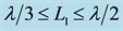 .
.
liptic integrals of the first kind and its complement,  and
and  with
with . The impedance of a pair of coplanar strips can be then derived as
 (2)
(2)
 (3)
(3)
For the given line width , Figure 2(a) also illustrates that the impedance of a meander line section on the substrate (
 and
and ) is dependent upon the pitch A. One can calculate the impedance of a meander line section on a substrate by
 (4)
(4)
where ,
,  is the wave number in free space. The equivalent inductance
  of each meander section is
 (5)
(5)
and  is the operating frequency. For an antenna with
  meander line sections, the total inductance is
 .
.
It has been known that any attempt to reduce the size of a monopole while preserving the same natural frequency leads to bandwidth deterioration, pattern distortion, and gain reduction. Thus an antenna’s dimension must be on the same order as the wavelength to radiate at maximum efficiency. Given a quasi-monopole antenna of reduced length  as shown in Figure 1(c), its reactance may be similar to that of a monopole antenna and can be obtained by the induced electromagnetic field,
 (6)
(6)
where  is an intrinsic impedance,
  is permeability,
  is permittivity,
  and
and 
are the cosine and sine integrals,  and
and , and
, and  is the equivalent
radius of the antenna. Figure 2(b) illustrates that the radiation reactance is negative if the antenna length , and it will decrease further as
  becomes smaller, hence reducing the antenna efficiency. At
 , the reactance can be approximated by a linear function. The meander line sections with positive inductance are therefore required to compensate the printed meander line antenna by
 (7)
(7)
where  is the radiation reactance of a quasi-monopole antenna and
  is the number of meander line sections of the antenna. In antenna design within a given area,
  is first defined and the radiation reactance of the quasi-monopole antenna is calculated by Equation (6), then the number
  and geometry (
 and
and ) of the meander line section can determined by the inductor model in Equation (5).
3. Antenna Design and Experiment
Consider a printed meander line antenna operating at  on a substrate
 . For
. For ,
,  , and
, and , the impedance of the meander line section from Equation (5) is
 . Two meander line sections
  are to compensate the radiation reactance of the quasi-monopole antenna, and the antenna of length
  with
with  can be predicted by the interpolation in Figure 2(b). Table 1 lists six printed meander line antennas operating at the same frequency. For an antenna of length
 , one can have 2 meander line sections of
  or 3 meander line sections of
  as shown in Figure 3(a) and Figure 3(b). Both achieve the same operating frequency. Similarly for the antenna of length
 , there are two designs for the same frequency: 3 meander line sections at
  or 2 at
 . For the meander line antenna of length
 , either 2 meander line sections at
  or 1 at
  is capable to operate at
 . These analyses validate the inductor model in predicting the inductance of the meander line sections and in approximating the reactance of the quasi-monopole. The radiation pattern of a meander line antenna is similar to that of a monopole antenna as illustrated in Figure 3(c).
The meander line antenna aims at reducing the physical dimension while maintaining the required electrical length. However, because of the corner effects between the adjacent meander line sections, the antenna length will be higher than  of monopole. The effects of the number of the meander line sections are illustrated as follows. Consider a printed monopole antenna of length
  at
at . Multiple meander line sections with
  at different
  and
and  are added to the monopole while keeping the total length constant. By using the inductor model, the inductance of the meander line sections can be calculated, and the resonant frequency is shown to decrease with increasing
  and
and  as listed in Table 2. The reactance of the quasi-monopole and the resonant frequency are plotted in Figure 4, where they are shown within acceptable accuracy as predicted by the inductor model. These results indicate that if the geometry limit of a meander line antenna is known, then the antenna length and reactance can be calculated and the meander line section can be determined.
4. Experimental Verification
Smart structures integrating sensor/actuator offer many potential advantages in vibration control and structural
health monitoring. A smart layer module utilizing flexible printed circuit process to encapsulate sensor/actuator and electrical circuit in polyimide layers has been recently developed [4] , and an antenna embedded in composite laminated substrate has been shown to achieve better performance oven that attached on an isotropic sub-

Table 1. The dimension of a printed meander line antenna operating at 900 MHz.
Table 2. The resonant frequency (MHz) of a meander line antenna as function of the number of meander line sections  and width W (mm) at pitch
 .
.

 (a) (b)
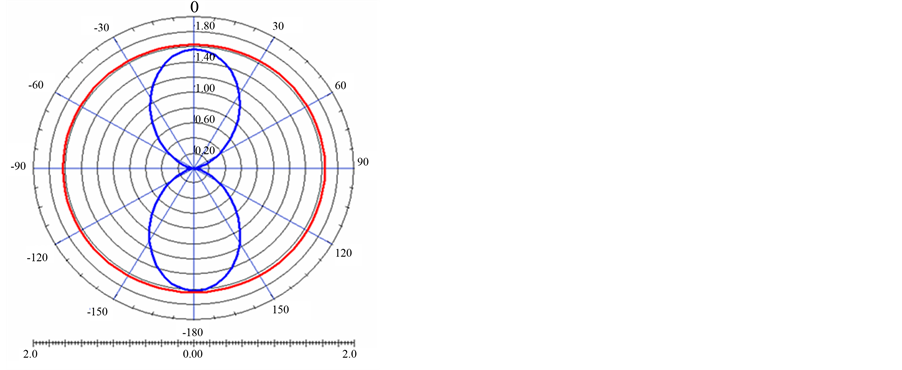 (c)
(c)
Figure 3. Configuration of the printed antennas operating at 900 MHz, (a) ,
, 
 and (b)
 ,
,  ,
,  and (c) the antenna pattern of a meander line antenna similar to that a monopole antenna.
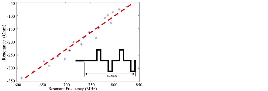
Figure 4. The reactance of a quasi-monopole due to length reduction can be compensated by the meander line sections with  at different W and number of section M.
strate [5] . By the smart layer concept, the printed meander line antennas ( ,
,  , and
, and ) are embedded inside the [45/−45/45/45/−45/45] symmetric substrate of thickness
  to verify the inductor model.
The substrate is composed of woven fiber glass prepreg tapes with Young’s modulus 36 GPa, shear modulus 5.7 GPa, Poisson ration 0.24, and average density 1681 Kg/m3 in ±45˚ symmetric cross-ply. The polyimide layer for the antenna and flexible printed circuit consists of two layers: a dielectric base layer (CRI-0512S, DuPont) of 12.5 mm thickness and a copper layer of 17.5 mm thickness. Shielding is by the copper film on the back side of the polyimide layer to reduce back-radiation. An SMA (subminiature version A) connector of 50 Ω impedance is attached at the feed line (length  and width
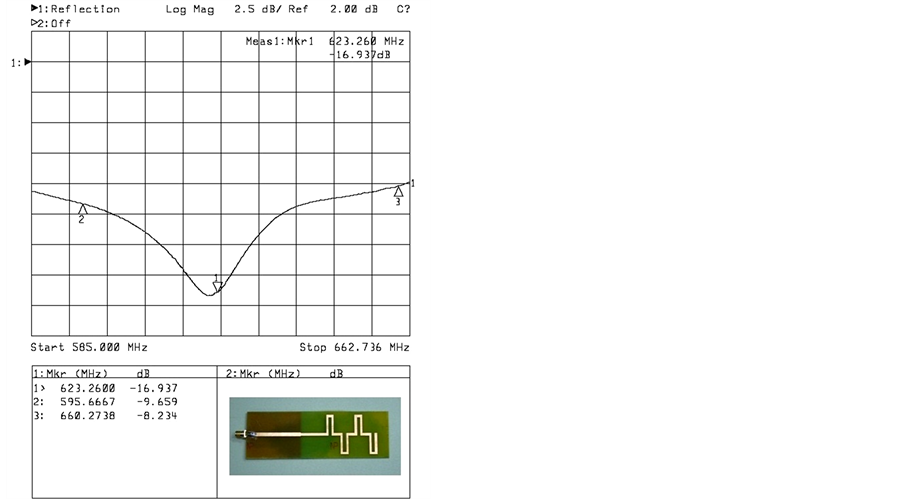
 ) on the polyimide layer. Figures 5(a)-(d) shows the resonant frequency comparison of the prediction by the inductor model and the measurement by the network analyzer (Agilent 8714ET). The experimental results of the resonant frequency are at 797, 734,
 (a) (b)
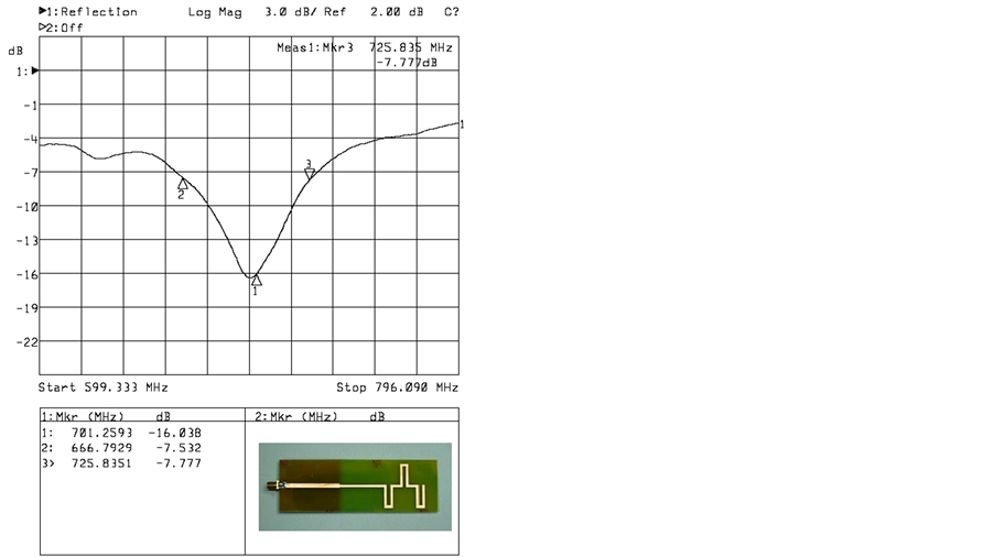
 (a) (b)
Figure 5. Measurement of the return loss of the printed meander line antennas, (a) illustration of a meander line antenna embedded in the composite laminated substrate; (b)  with
with ; (c)
; (c)  with
with ; (d)
; (d)  with
with ; and (e)
  with
with .
.
701, and 623 MHz, respectively, for the meander line antennas M = 1 to 4, and they are also listed on Table 2. The predictions from the inductor model are in good agreement, and the discrepancies are within 6.4%. These validations confirm that the inductor model is effective to design and analysis of a printed meander line antenna. It should be noted that the bandwidth of printed meander line antennas decreases with the antenna length. The radiation pattern is determined by the current distribution on the meander line. As a consequence of the current cancellation and reinforcement, a number of high resonances may be present in meander line antenna. Care has to be taken since these resonances often result in low voltage standing wave ratio (VSWR) when embedding the antenna in composite laminated substrate.
5. Conclusions
1) Recent smart structure development of Conformal Load-bearing Antenna Structure (CLAS) by embedding microstrip antenna inside composite laminated substrates has been considered desirable to have sufficient structural and antenna performance. Meander line antenna can be installed in airframe to eliminate air drag and minimize aerodynamic disturbance. An inductor model is developed to facilitate systematic design and analysis of the antenna. The meander line sections providing positive inductance are modeled by the inductors while the radiation parts are by a quasi-monopole of much shorter length.
2) The inductor model shows that the reactance of a quasi-monopole antenna can be calculated by a linear function at . The reactance can be compensated by that of the meander line sections, which are determined by the geometry parameters A, D, W and M. The polarization of a meander line antenna is similar to a monopole antenna when the length of the meander line section (W) is small compared to the antenna length. Based on the smart layer concept, four meander line antennas (
 ,
,  ,
,  ,
,  , 2, 3 and 4) on polyimide layer are developed, and they are embedded in [45/−45/45/45/−45/45] symmetric composite laminated substrates. Discrepancies of resonant frequency between the prediction of the inductor model and the measurement results are within 4.6%.
Acknowledgements
This work was supported in part by the National Science Council, Taiwan, ROC under NSC100-2221-E006- 098-MY3.
References
- Yang, S.M. and Chen, C.W. (1996) Application of Single Mode Optical Fiber in Structural Vibration Suppression. Journal of Intelligent Material Systems and Structures, 7, 71-77. http://dx.doi.org/10.1177/1045389X9600700108
- Yang, S.M. and Bian, J.J. (1996) Vibration Suppression Experiment of Composite Laminated Plates by Embedded Piezoelectric Sensor and Actuator. Smart Materials and Structures, 5, 501-507. http://dx.doi.org/10.1088/0964-1726/5/4/014
- Yang, S.M. and Jeng, C.A. (1996) Structural Vibration Suppression by Concurrent Piezoelectric Sensor and Actuator. Smart Materials and Structures, 5, 806-813. http://dx.doi.org/10.1088/0964-1726/5/6/011
- Yang, S.M. Hung, C.C. and Chen, K.H. (2005) Design and Fabrication of a Smart Layer Module in Composite Laminated Structures. Smart Materials and Structures, 14, 315-320. http://dx.doi.org/10.1088/0964-1726/14/2/003
- Yang, S.M. and Hung, C.C. (2009) Modal Analysis of Microstrip Antenna on Fiber Reinforced Anisotropic Substrates. IEEE Transaction on Antennas and Propagation, 57, 792-796. http://dx.doi.org/10.1109/TAP.2009.2013443
- Chan, K.K., Ang, T.W. and Chio, T.H. (2008) Accurate Analysis of Meanderline Polarizers with Finite Thicknesses Using Mode Matching. IEEE Transaction on Antennas and Propagation, 56, 3580-3585. http://dx.doi.org/10.1109/TAP.2008.2005548
- Eldek, A.A. (2008) Analysis and Design of a Compact Multi-band Antenna for Wireless Communication Applications. Microwave Journal, 51, 281.
- You, C.S., Hwang, W. and Eom, S.Y. (2005) Design and Fabrication of Composite Smart Structures for Communication, Using Strucutral Resonance of Dadiated Field. Smart Materials and Structures, 14, 441-448. http://dx.doi.org/10.1088/0964-1726/14/2/019
- Zhao, X.L., Qian, T., Mei, G., Kwan, C., Zane, R., Walsh, C., Paing, T. and Popovic, Z. (2007) Active Health Monitoring of an Aircraft Wing with an Embedded Piezoelectric Sensor/Actuator Network: II. Wireless Approaches. Smart Materials and Structures, 16, 1218-1225.
- Ramesh, P. and Washington, G. (2009) Analysis and Design of Smart Electromagnetic Structures. Smart Materials and Structures, 18, Article ID: 104006.
- Son, S.H., Eom, S.Y. and Hwang, W. (2008) Development of a Smart-Skin Phased Array System with a Honeycomb Sandwich Microstrip Antenna. Smart Materials and Structures, 17, 1-9.
- Jang, H.K., Lee, W.J. and Kim, C.G. (2011) Design and Fabrication of a Microstrip Patch Antenna with a Low Radar Cross Section in the X-Band. Smart Materials and Structures, 20, Article ID: 015007.
- Nakano, H., Tagami, H., Yoshizawa, A. and Yamauchi, J. (1984) Shortening Ratios of Modified Dipole Antennas. IEEE Transactions on Antennas and Propagation, 32, 385-386. http://dx.doi.org/10.1109/TAP.1984.1143321
- Warnagiris, T.J. and Minardo, T.J. (1998) Performance of a Meandered Line as an Electrically Small Transmitting An- tenna. IEEE Transactions on Antennas and Propagation, 46, 1797-1801. http://dx.doi.org/10.1109/8.743815
- Suh, Y.H. and Chang, K. (2000) Low Cost Microstrip-Fed Dual Frequency Printed Dipole Antenna for Wireless Com- munications. Electronics Letters, 36, 1177-1179. http://dx.doi.org/10.1049/el:20000880
- Tong, K.F., Luk, K.M., Chan, C.H. and Yung, E.K.N. (2000) A Miniature Monopole Antenna for Mobile Communications. Microwave and Optical Technology Letters, 27, 262-263. http://dx.doi.org/10.1002/1098-2760(20001120)27:4<262::AID-MOP13>3.0.CO;2-O
- Yan, Z.Z. and Majedi, A.H. (2009) Experimental Investigations on Nonlinear Properties of Superconducting Nanowire Meanderline in RF and Microwave Frequencies. IEEE Transactions on Applied Superconductivity, 19, 3722-3729.
- Vinoy, K.J., Jose, K.A., Varadan, V.K. and Varadan, V.V. (2001) Hilbert Curve Fractal Antenna: A Small Resonant Antenna for VHF/UHF Applications. Microwave and Optical Technology Letters, 29, 215-219. http://dx.doi.org/10.1002/mop.1136
- Vinoy, K.J., Jose, K.A. and Vardan, V.K. (2001) Design of Reconfigurable Fractal Antennas and RF-MENS for Space- Base Systems. Smart Materials and Structures, 10, 1211-1223.
- Trarassos, X., Lisboa, A.C. and Vieira, D.A.G. (2012) Design of Meander-Line Antennas for Radio Frequency Identification Based on Multiobjective Optimization. International Journal of Antennas and Propagation, 2012, Article ID: 795464.