Journal of Electromagnetic Analysis and Applications
Vol.4 No.11(2012), Article ID:24709,4 pages DOI:10.4236/jemaa.2012.411064
Comparison of Circular Sector and Rectangular Patch Antenna Arrays in C-Band
![]()
1Laboratoire d’Electronique et de Communications_LEC Ecole Mohammadia d’Ingénieurs—EMI, Université Mohammed V-Agdal, Rabat, Morocco; 2Electrical Enegenniring Department, Ecole Supérieure de Technologie—ESTM, Université Moulay Ismail, Meknes, Morocco.
Email: anouar_dalli@yahoo.fr
Received September 5th, 2012; revised October 5th, 2012; accepted October 16th, 2012
Keywords: Circular Sector Microstrip Antenna; Rectangular Antenna; Antenna Array; Gain; Directivity; HFSS
ABSTRACT
The circular sector patch antenna is studied in C-band (4 GHz - 8 GHz). In this paper, we present steps of designing the circular sector antenna then a comparison with a rectangular antenna in literature. High Frequency Structure Simulator (HFSS) software is used to compute the gain, axial ratio, radiation pattern, and return loss S11 of proposed antenna. Based on the designed patch antenna, many phased arrays will be simulated using HFSS. The impact of distance between element, number of element and phase will be checked. Obtained results are analyzed and compared with literature.
1. Introduction
Modern Wireless communication Systems require low profile, lightweight, high gain and simple structure antennas to assure reliability, mobility, and high efficiency. A patch antenna is very simple in construction using a conventional microstrip fabrication technique [1-5]. It consists of a patch of metallization on a grounded dielectric substrate. They are low profile, lightweight antennas, most suitable for aerospace and mobile applications. Patch antennas have matured considerably during last years, and many of their limitations have been overcome [6].
The conducting patch can take any shape, but rectangular configurations are the most commonly used. In our study we are interested in circular sector shape, because of their small size compared with other shapes like the rectangular and circular patch antennas and provide circular polarization which is desired in wireless communication. Rectangular patch antenna will be introduced as reference and its performance will be compared with circular sector antenna. The chosen rectangular antenna is designed by Pozar in [1].
In this study, several designs of rectangular and circular sector patch antennas arrays are presented. We will compare single element of both shapes, then array of patch antenna will be designed using theory of array factor. Moreover, these designs are simulated using HFSS. Based on the simulation results, comparison between both rectangular and circular sector patch antennas array is achieved in C-Band. This band contains frequency ranges that are used for many satellite communications transmissions, some Wi-Fi devices, some cordless telephones, and some weather radar systems.
This paper is divided into four sections: the first section is devoted to give an overview of the patch antennas and a preface of the important parameters in single element designs, for both rectangular and circular sector. Second section discusses the antenna arrays based on rectangular and circular sector antenna. Third section presents a comparison between both shapes. Finally, a brief conclusion is presented in the fourth section.
2. Single Element Study
2.1. Theory
Patch antenna design in C-band and with optimal characteristic is the overall objective of this section. To achieve this overall objective, the primary task is to choose a suitable geometry of the patch for the antenna. The proposed shape is circular sector patch. The Rectangular patch will be treated as reference antenna, because there is a series of more mature theory as a basis for analysis of rectangular patch antenna, such as the transmission line method, cavity model method [2].
Circular sector and rectangular patch antenna structure are shown in Figure 1.
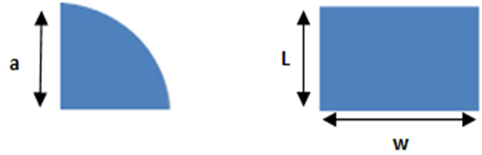
Figure 1. Geometry of both rectangular and circular sector patch antennas.
For rectangular patch antenna, suppose patch length is L, patch width is W, dielectric thickness is h, dielectric constant is εr, light speed is c, resonant frequency is fr, wavelength is λ. from [4], we found:
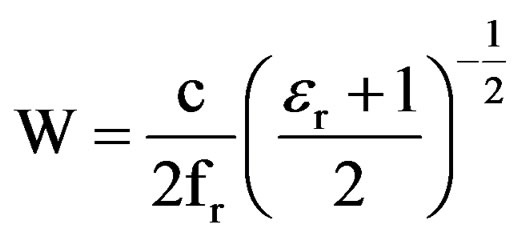 (1)
(1)
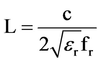 (2)
(2)
It is worth to mention that, the rectangular patch width W has a minor effect on the resonant frequency and radiation pattern of the rectangular patch antenna.
For circular sector patch antenna, the expression of the radius “a” of the patch is [3]:
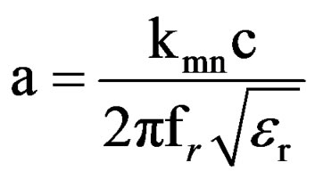 (3)
(3)
kmn is the zero of the equation J'(kmn) = 0. J is the Bessel function.
2.2. Design
2.2.1. Substrate Selection
One of major steps in designing a patch antenna is to choose a suitable substrate of appropriate thickness, permittivity and loss tangent. The substrate is often a dielectric with a permittivity of between 2.1 and 25. Substrates based on polytetrafluoroethylene (PTFE) are widely used because of their electrical and mechanical characteristics [2].
Most of the microstrip antenna work in the past has employed electrically thin, low permittivity substrates. Recent interest in millimeter wave systems and miniaturized structure [1] has created a need for substrates that are electrically thicker and/or have high permittivity. Increased bandwidth is another reason for interest in electrically thicker substrates.
The proposed antennas are designed using the substrate FR 4 (permittivity ε = 4.4, tanδ = 0.02) which is widely used for patch antennas, RO3006 (permittivity ε = 6.5, tanδ = 0.0025) and RO3200 substrate (εr = 10.2, tanδ = 0.0035) was used in [1] for our reference antenna.
RO3210 and RO3006 was chosen because they are based on Polytetrafluoroethylene (PTFE) which are widely used because of their electrical and mechanical characteristics [3] minimum cost and permit to have a miniature antenna with a minimum loss. In references, we cited some use of this substrate in emerging application [7-9].
2.2.2. Choice of Type of Feeding
The most used feeding mode for patch antenna is: Microstrip line, coaxial cable or proximity coupling. The feeding microstrip line and coaxial cable feed are easy to implement, but, this type of feeding generates a parasite radiation which affects the radiation pattern. The proximity coupling offer greater bandwidth and better radiation pattern but it’s not easy to implement.
In this article we have chosen to feed our antenna via a microstrip line and secondly via a coaxial cable. We will compare the results for these two modes of feeding.
2.2.3. Design of Single Element
Figure 2 shows the design of rectangular microstrip antenna studied in [1]. Same dimension, feeding mode and substrate has benn reproduced in HFSS.
As shown in the Figure, both patches are fed by microstrip line. Substrate thickness is h = 0.127 cm. Dimension of patch are: W = 0.75 cm and L = 0.5 cm.
For circular sector microstrip antenna, we change only the shape of patch; all other parameters are same as Pozar’s antenna. The circular sector patch angle is α = 90˚ and radius a = 1 cm. Figure 3 shows the architecture of the proposed antennas.
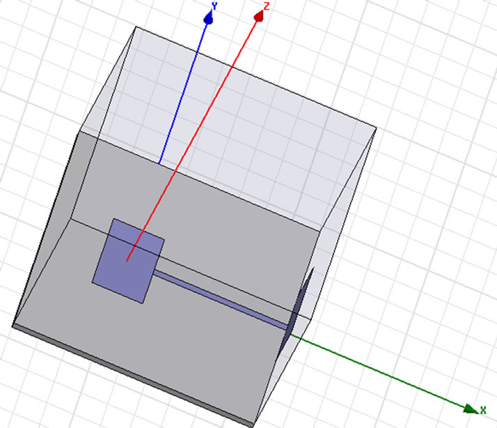
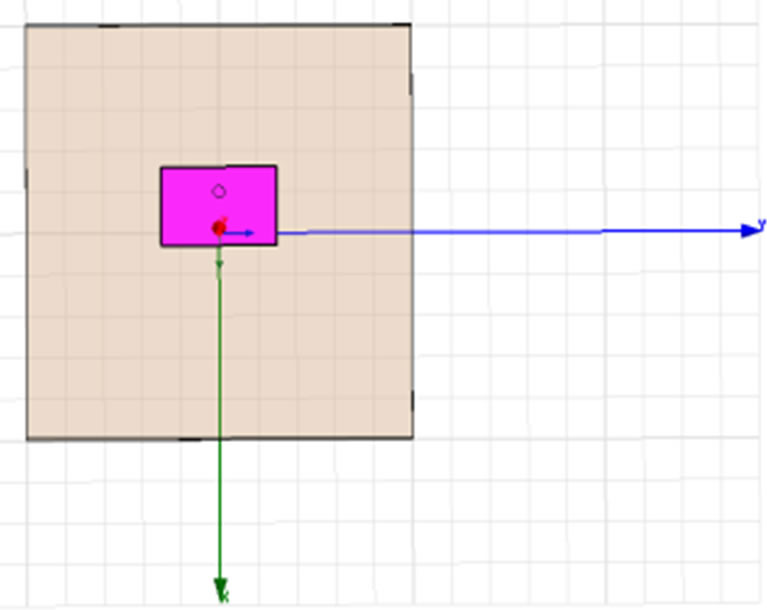
Figure 2. Rectangular patch antenna designed by Pozar in [1].
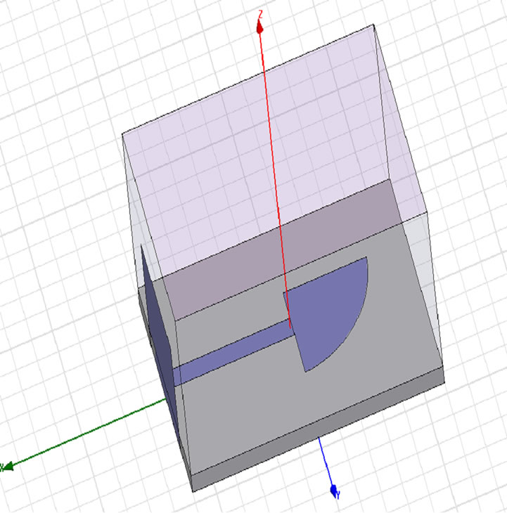
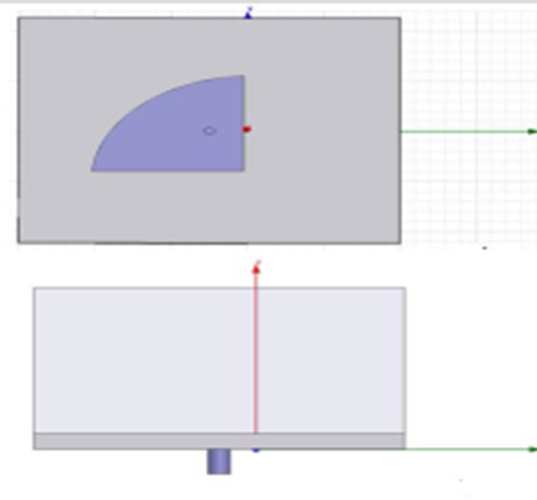
Figure 3. Circular sector patch antenna designed in HFSS fed by coax and microstrip line.
2.3. Results and Analysis
2.3.1. Effect of Changing Shape of Patch
2.3.1.1. Return Loss Comparison
Figure 4 shows the return loss simulated for both rectangular and circular sector microstrip antennas. Circular sector antenna resonates for three frequencies: 4.48 GHz, 5.27 GHz and 7.8 GHz with return loss between –12 dB and –14 dB. But for reference antenna, it resonates for 4.32 GHz but the return loss doesn’t exceed –11 dB. So when could say that circular sector microstrip antenna exploit the C-band better than rectangular microstip antenna.
2.3.1.2. Polarization To determine the nature of the polarization, we have to calculate axial ratio. In this paper, we are interested to the circular polarization. In this case, for circular polarization axial ratio should not exceed 3 dB. Figures 5 and 6 present axial ratio calculated using HFSS to compare the polarization of circular sector and rectangular microstrip antenna [10-11].
In Figure 5, the axial ratio is inferior to 3 dB for resonant frequencies (4.48 GHz, 5.27 GHz and 7.8 GHz), so for circular sector antenna we had circular polarization for resonant frequency for both feeding mode, which was already planned since the polarization is independent of feeding mode. This result is important because we could obtain a circular polarization with a single fed antenna and without the need to add a perturbation to patch or add a second fed.
But for Figure 6, the axial ratio is superior to 3 dB for resonant frequencies (4.32 GHz), so for rectangular microstrip antenna we had linear polarization for resonant frequency for both feeding mode, which was proved several time that rectangular had linear polarization.
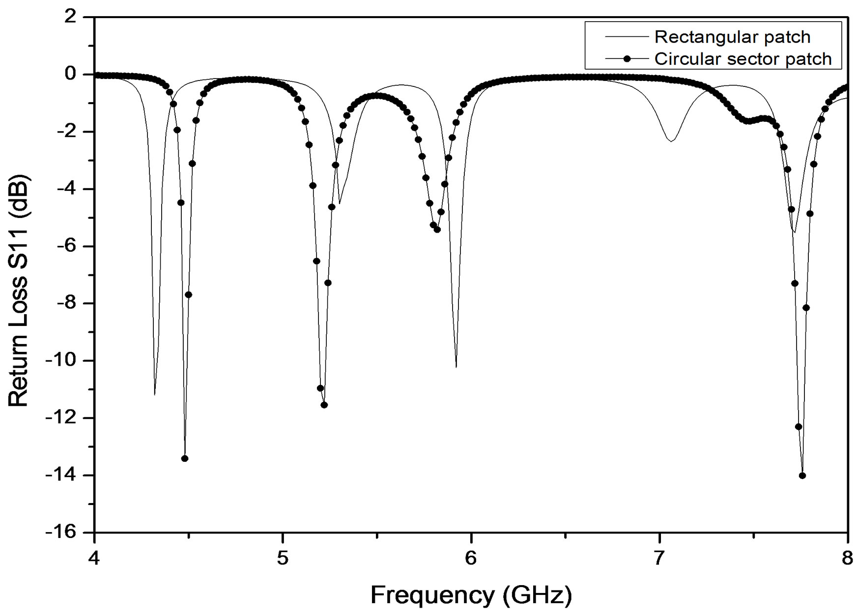
Figure 4. Return loss of rectangular and circular sector patch antenna in C-band.
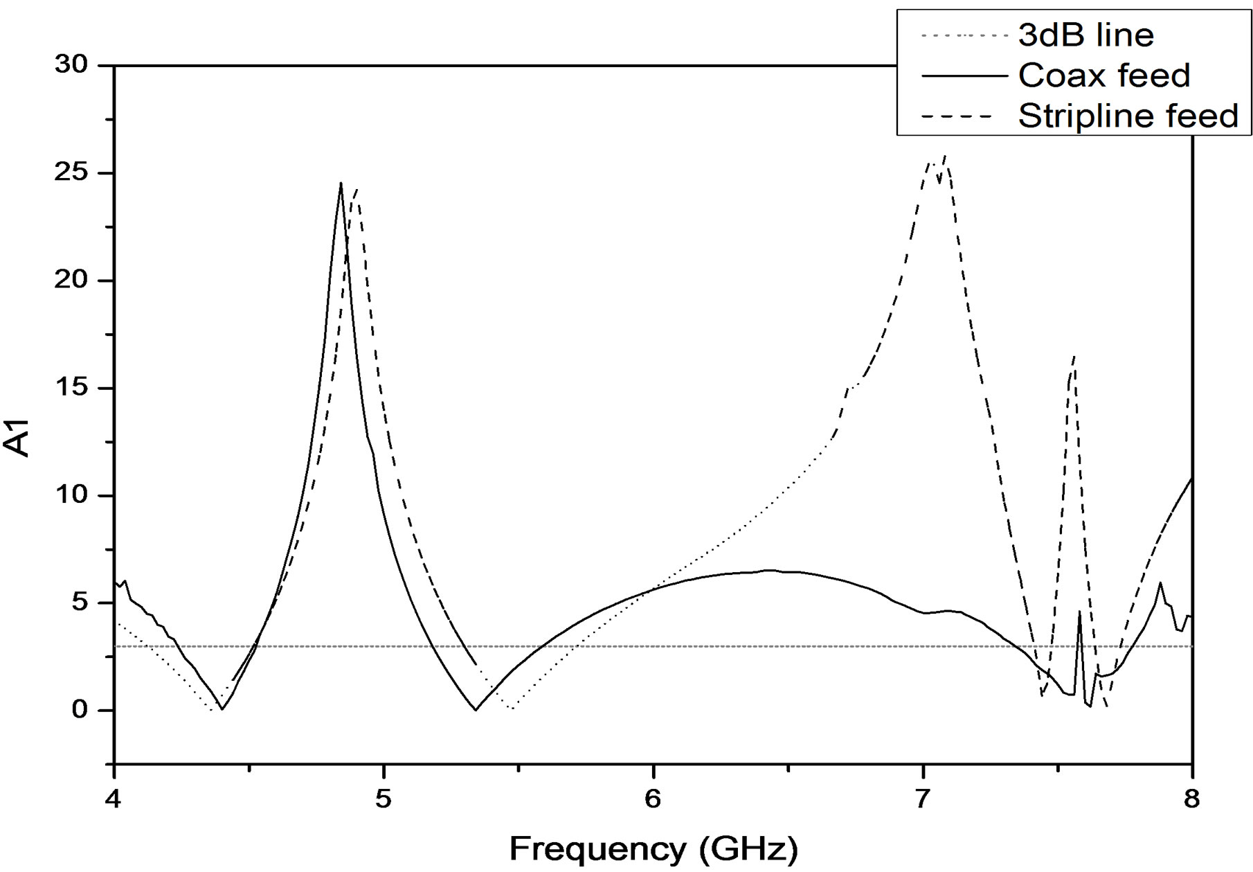
Figure 5. Axial ratio for circular sector microstip antenna fed by microstrip line and coax cable.
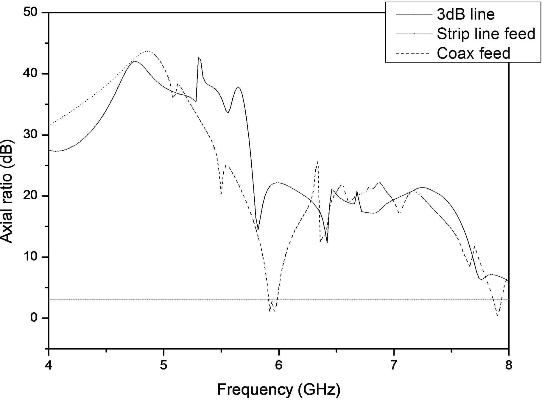
Figure 6. Axial ratio for rectangular microstip antenna fed by microstrip line and coax cable.
2.3.1.3. Radiating Pattern and Gain Radiation pattern in E-plan of circular sector and rectangular microstrip antenna are traced in Figures 7 and 8 for two feeding mode: Microstrip line and coax cable.
From the simulated results, it is shown that patterns of all antennas are directive and have similar form. The gain of the studied antenna is about 5 dB and 5.7 dB. So we can deduce that circular sector patch didn’t change the gain if we compare it to rectangular patch.
This limitation in generated gain will be overcome in the second section by using arrays.
2.3.2. Effect of Changing Feeding Mode for Circular Sector Antenna
The objective is to define effect of changing feeding mode. Figure 9 shows the return loss S11 of circular sector antenna fed.
These two feeding methods are very similar in operation, and offer essentially one degree of freedom (for a fixed patch size and substrate) in the design of the antenna element through the positioning of the feed point to adjust the input impedance level. For the case of a microstrip line feed, the patch can be notched to provide an inset feed point [6]. In Figure 9, the curve had the same shape but not the same resonant frequency. This difference is due to adaptation of microstrip line or the feeding point of coax cable. By adapting one of feeding mode we can reproduce the same resonant frequency.
2.3.3. Effect of Substrate for Circular Sector Antenna
Figure 10 show the return loss of circular sector antenna fed by microstrip line:
Changing substrate has a major effect on antenna even the return loss. For RO3200 (ε = 10.2) antenna resonate for (4.48 GHz, 5.27 GHz and 7.8 GHz) with maximum
 (a)
(a)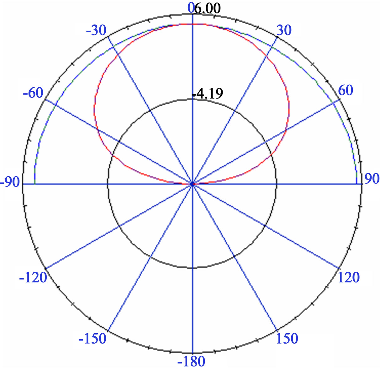 (b)
(b)
Figure 7. (a) Circular sector antenna fed by microstrip line radiation pattern in 4.48GHz; (b) Rectangular fed by microstrip line radiation pattern in 4.32 GHz.
 (a) (b)
Figure 8. (a) Circular sector antenna fed by coax cable radiation pattern in 4.48 GHz; (b) Rectangular fed by coax cable radiation pattern in 4.32 GHz.
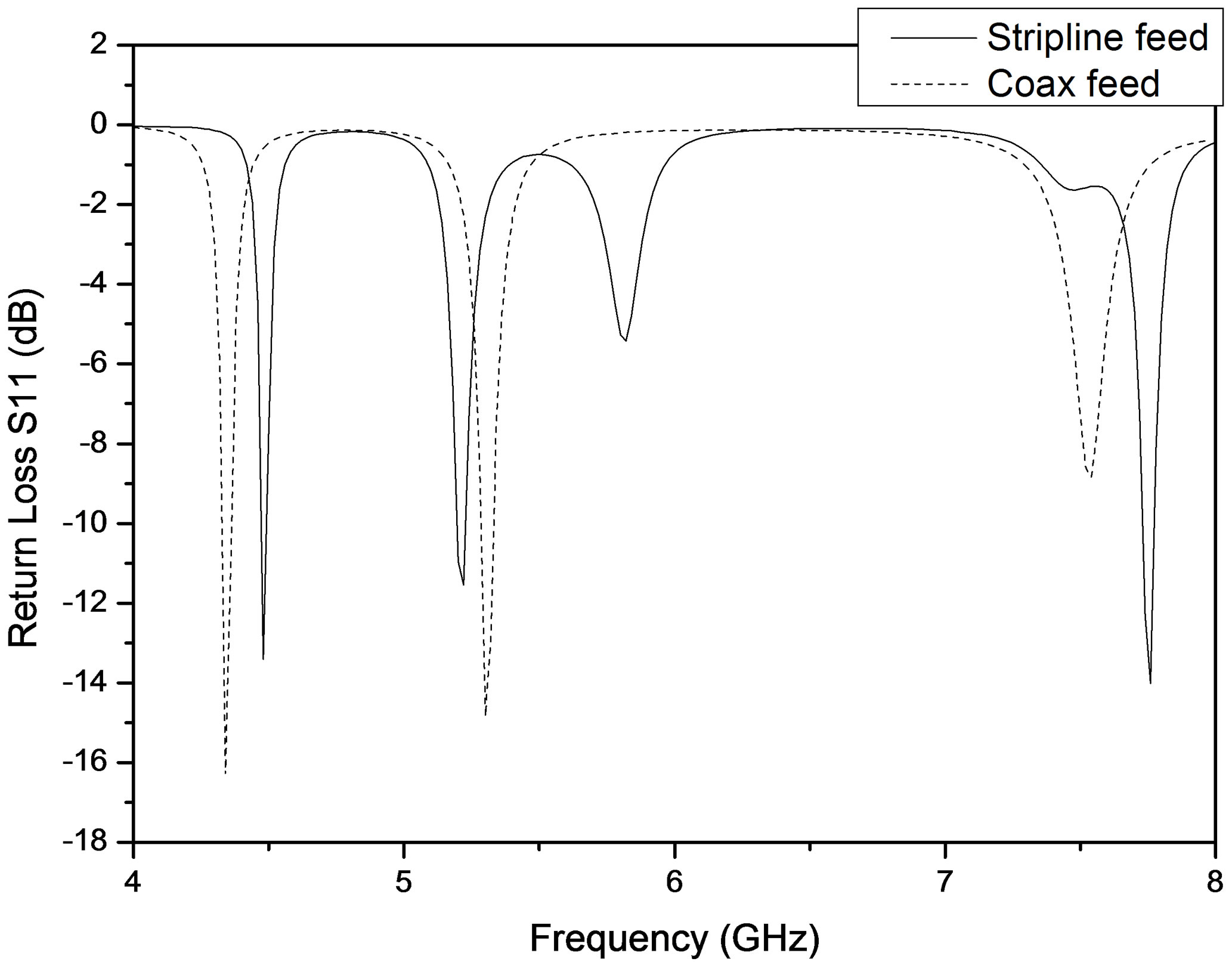
Figure 9. Return loss for circular sector microstrip antenna fed by microstrip line and coax cable.
return loss of –15 dB. For RO3006 (ε = 6.4) antenna resonant frequencies (4.87 GHz and 7.7 GHz) and return loss is –17 dB but for FR4 (ε = 6.4), antenna has one resonant frequency (6.6 GHz) with a good return loss –22 dB.
Hence we deduce that by using substrate with high permittivity changed the nature of the antenna: We switched from a broadband antenna with good reflection coefficient (–22 dB) to a multiband frequency antenna that can be used to cover C-Band with reflection coefficient S11 < –10 dB.
2.3.4. Comparison of Circular Sector Microstrip Antenna with Literature
In Table 1 we recapitulate characteristics of our proposed antenna and antenna designed by Pozar in [1]
Circular sector have interesting geometric dimension, as mentioned in Table 1, surface of circular sector is 0.785 cm2 and rectangular is 1.425 cm2. Another advantage that offer circular sector microstrip antenna is polarization.
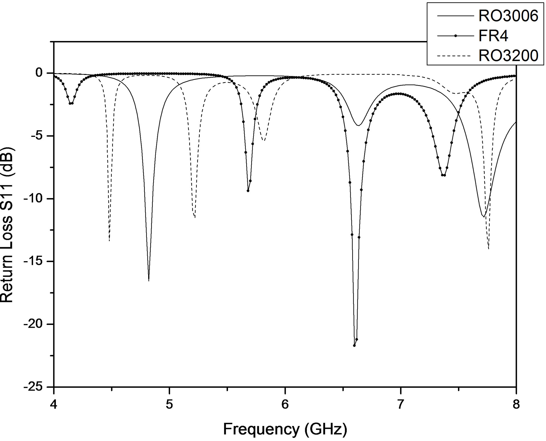
Figure 10. Effect of changing substrate of circular sector microstrip antenna.
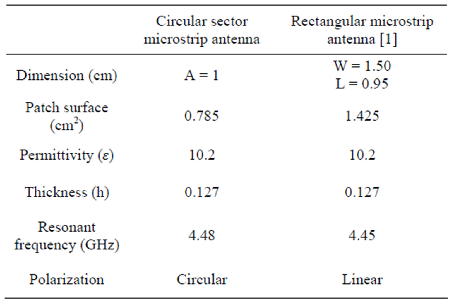
Table 1. Comparison rectangular and circular sector microstrip antenna.
It permits to have circular polarization without complicating architecture.
3. Study of Antenna Array
3.1. Theory
In certain applications, desired antenna characteristics may be achieved with a single microstrip element. However, in other case, characteristics such as high gain, beam scanning, or steering capability are possible only when discrete radiators are combined to form arrays [2]. The elements of an array may be spatially distributed to form a linear, planar, or volume array. A linear array consists of elements located finite distances apart along a straight line. In practice, the array type is usually chosen depending on the intended application.
The radiation pattern of the network depends on many parameters. Referring to studies performed on more antenna arrays that the expression of the general network is as follows [4]:
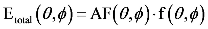 (4)
(4)
The term f (θ, φ) represents the vector electrical potential created in the region of radiation by the reference antenna. It only depends on the type of antenna and power distribution. It is called element factor.
The term AF (θ, φ) depends only on the relative positions of antennas in the series and relationships between the current distributions. This is the array factor.
The angles θ, φ represent the coordinates of a polar M in space having a distance r from the array.
Since the radiator was already fixed: Circular sector or rectangular microstrip antenna. Then for calculating the fields radiated by the antenna array we will focus on determining factor network (AF).
3.2. Design
3.2.1. Design of Linear Array
A uniform array is defined by uniformly-spaced identical elements of equal magnitude with a linearly progressive phase from element to element (see Figure 11).
It is assumed that each succeeding element has a progressive phase lead current excitation relative to the preceding one. An array of identical elements with identical magnitudes and with a progressive phase is called a uniform array.
The AF can be obtained by considering the individual
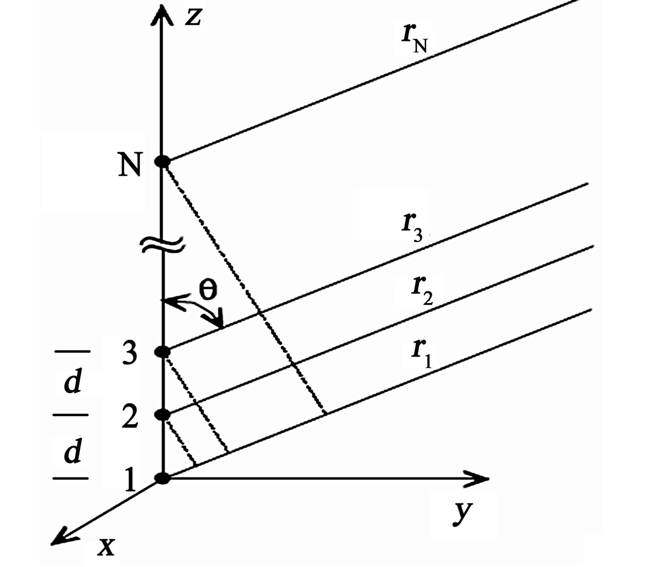
Figure 11. Linear phased array [4].
elements as point (isotropic) sources. If the elements are of any other pattern, the total field pattern can be obtained by simply multiplying the AF by the normalized field pattern of the individual element [4].
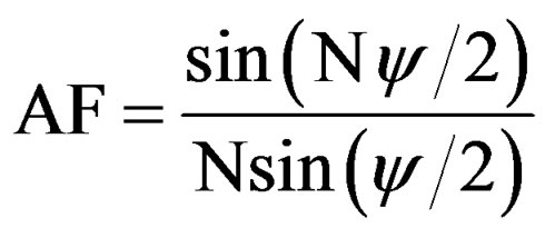 (5)
(5)
The function ψ is defined as the array phase function and is a function of the element spacing, phase shift, frequency and elevation angle:
 (6)
(6)
3.2.2. Design of Planar Array
Planar arrays provide directional beams, symmetrical patterns with low side lobes, much higher directivity (narrow main beam) than that of their individual element. In principle, they can point the main beam toward any direction (see Figure 12).
If N such arrays are placed at even intervals along the y direction, a rectangular array is formed. We assume again that they are equi-spaced at a distance dy and there is a progressive phase shift βy along each row. We also assume that the normalized current distribution along each of the x-directed arrays is the same but the absolute values correspond to a factor of I1n (n = 1, ×××, N). Then, the AF of the entire MxN array is [4]
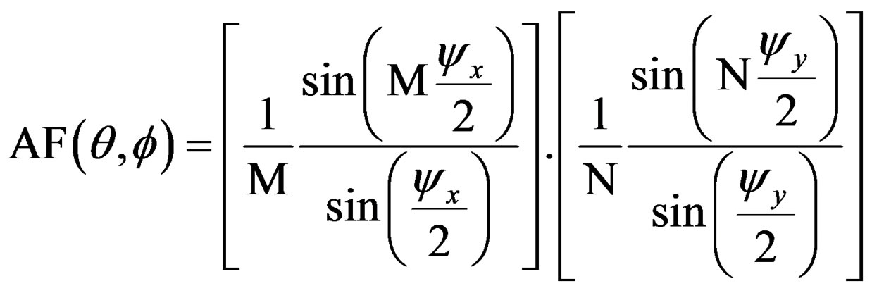 (7)
(7)
Same as linear array, the functions ψx and ψy are defined as the array phase function and are a function of the element spacing, phase shift, frequency and elevation angle:
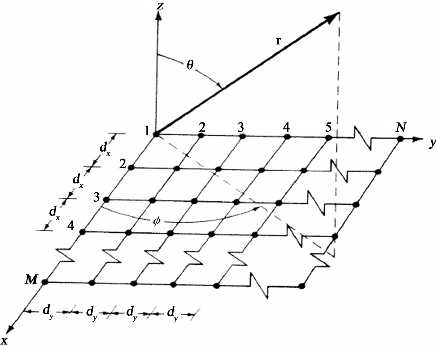
Figure 12. Planar phased array [4].
 (8)
(8)
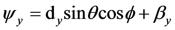 (9)
(9)
Actually, in order to make fair comparison, the same substrate used in single element (εr = 10.2 and thickness h = 0.127 cm), is used for all proposed arrays.
3.2.3. Methodology of Design
The antenna arrays will be designed using HFSS. The software enables to compute antenna array radiation patterns and antenna parameters for designs that have analyzed a single array element. HFSS models the array radiation pattern by applying the “array factor” on the single element’s pattern [12].
Figure 13 shows the interface for designing arrays, we can we can define array geometry: distance between element, number of element, phase of excitation.
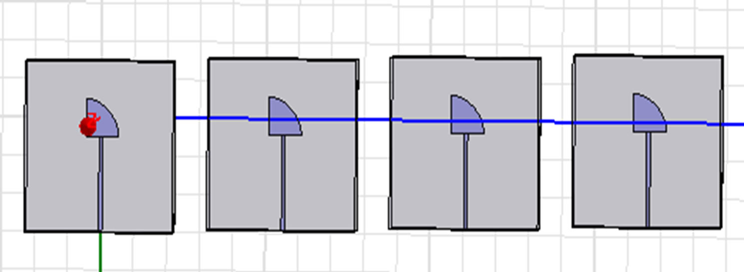
By following this methodology we can design planar and linear array as shown in Figure 14.
3.3. Results and Analysis
3.3.1. Influence of Inter-Element Distance
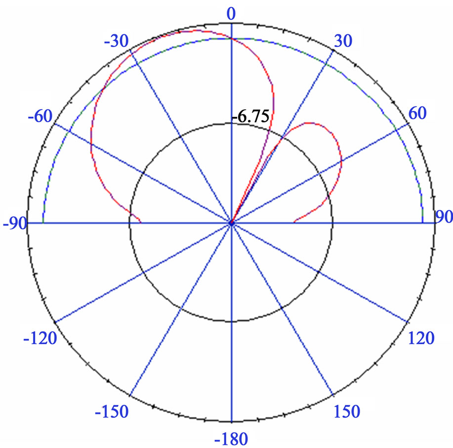
In this subsection, we analyze the influence of the interelement distance d on radiation pattern, as illustrated in Figure 14 given below. The studied array is composed of 4 elements in linear position and feeding phase is 45˚ based on circular sector and rectangular microstirp antenna.
It can be observed clearly that the beam widths of all major lobes became narrow and the number of minor lobes increases, when the inter-element distance increases. In addition, it can be found that for the all arrays the directions of major lobes are not fixed, while the distance is varied. Furthermore it is also observed that arrays provide beam steering for both patch shape (see Figure 15).
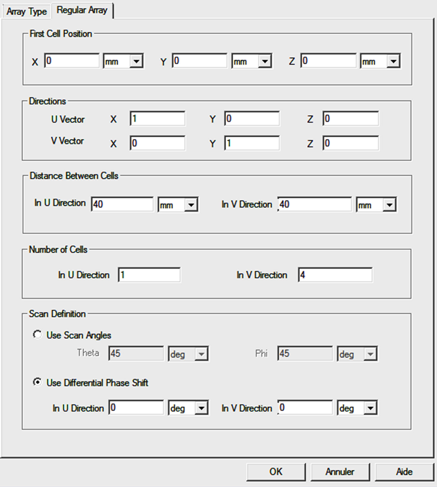
Figure 13. HFSS interface designing arrays.
 (a)
(a) 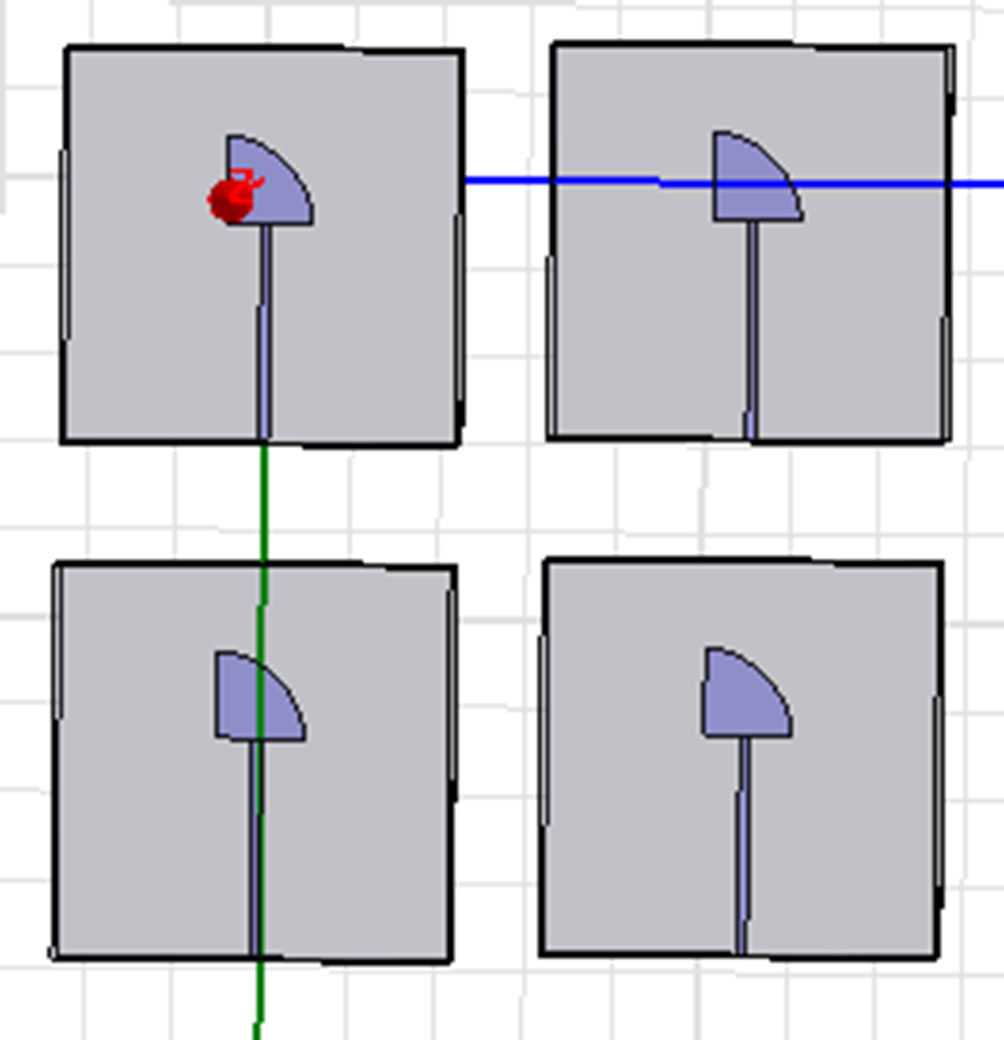 (b)
(b)
Figure 14Some designed arrays using HFSS. (a) Linear; (b) Planar. (a) Four élement circular sector microstrip antenna linear; (b) Four élement circular sector microstrip antenna linear array.
3.3.2. Influence of Element Number
The Table 1 show generated gain for circular sector and rectangular microstrip antenna array for different number of elements (N = 4; 6; 10; 14).
 (a)
(a)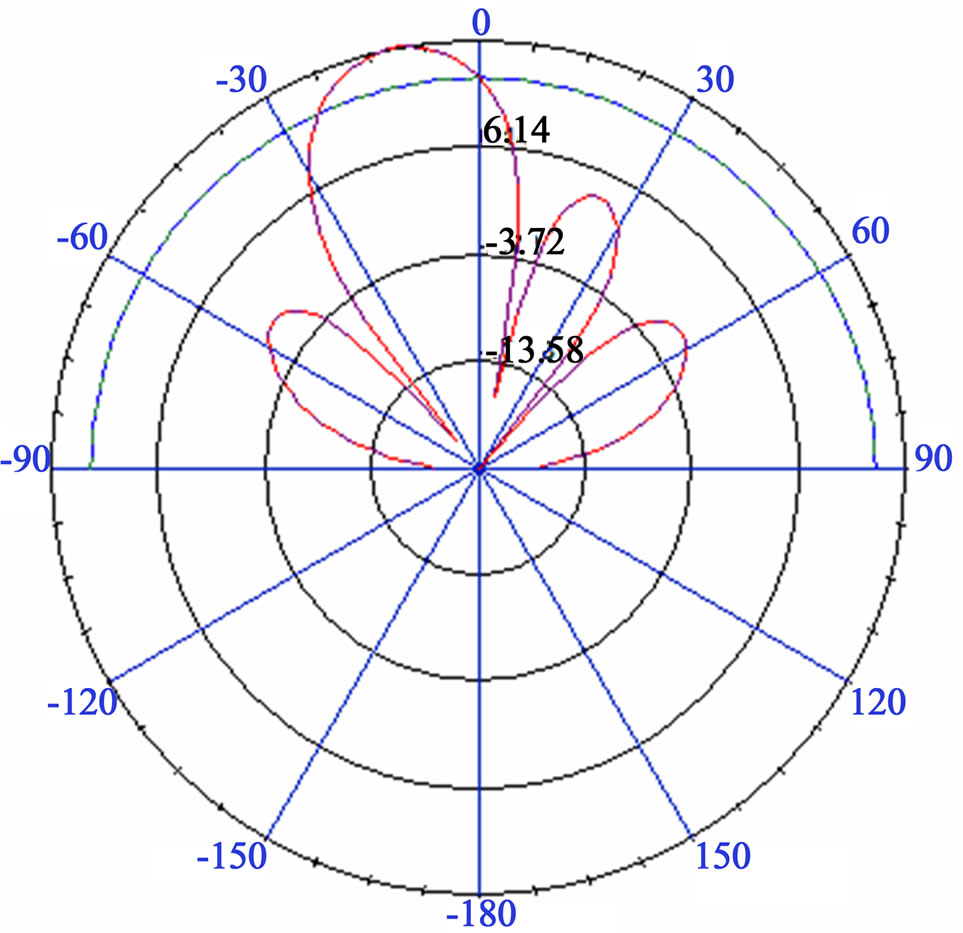 (b)
(b)
Figure 15. Influence of changing inter-element spacing for circular sector and rectangular microstrip antenna. (a) Inter-element distance d = 0.4λ; (b) Inter-element distance d = 0.6λ.
For array with larger the number of elements, the total gain increase for both arrays. But if we compare realized gain for rectangular and circular sector antenna array. We can deduce that gain of circular sector antenna array is superior to gain of rectangular microstrip antenna arrays.
But we cannot increase number of element to infinite number, it’s important to take in consideration the dimension of array [13].
3.3.3. Influence of Feeding Phase
The position of the main beam can be moved or steered by introducing a phase shift (equivalently, a delay in time) between elements as shown in figure below:
In Figure 16, we can see that phase front is adjusted to steer the beam by individual control of the phase of excitation of each radiating element. For three values of feeding phase we can cover an area of 180˚.
So the phase shifters are electronically actuated to permit rapid scanning and are adjusted in phase to a value between 0˚ and 180˚. This result can be used for adaptive antenna.
Other designs in bibliography confirm that similar array could be used for smart antenna [14-16].
3.3.4. Linear vs Planar
Table 2 shows the obtained simulated results of directivity and gain for liner and planar arrays based on circular sector microstrip antenna and rectangular microstrip antenna.
As shown in Table 3, the results obtained from rectangular patch are very close to those obtained for circular sector patch. In the other side, both gain and directivity, for both shapes, are decreasing from linear array to planar array.
One of the main disadvantages of linear arrays is their inability to scan the beam in more than one dimension. For this reason, most practical applications that utilize large phased array antennas use arrays with planar geometries.
Planar arrays do have a drawback, however. Unlike linear arrays, where the array factor is proportional to number of antennas for all observation angles, the array factor of a planar array is not uniform. Which justify that the gain and directivity of a planar array is lower than linear array.
3.3.5. Comparison Proposed Array with Literature
In Table 4 we recapitulate characteristics of our proposed array and other array in literature [14].
In Table 4 we can confirm that our proposed antenna we have reduced the size of antenna element by using circular sector and high permittivity substrate. The difference will be more visible in array, proposed antenna can be used easily as an array.
In the other side gain and directivity of circular sector antenna array is comparable to gain of [14] it’s about 11 dB for gain and 12 dB for directivity.
4. Comparison of Rectangular and Circular Sector Patch Antenna
4.1. Single Element
From obtained results in Section 2, we can make a comparison of single element for both studied shapes:
Circular sector have interesting geometric dimension, surface of circular sector is 0.785 cm2 and rectangular is 1.425 cm2. So for same frequency band, circular sector shape reduce dimension of patch, therefore dimension of substrate can be reduced.
In C-band, Circular sector antenna resonates for three frequencies: 4.48 GHz, 5.27 GHz and 7.8 GHz with return loss between –12 dB and –14 dB. But for reference antenna, it resonates for 4.32 GHz and the return loss doesn’t exceed –11 dB. So when could say that circular sector patch antenna exploit the C-band better than rectangular patch antenna.
For circular sector patch antenna the axial ratio is inferior than 3 dB for resonant frequencies (4.48 GHz, 5.27 GHz and 7.8 GHz), but the axial ratio is superior to 3dB
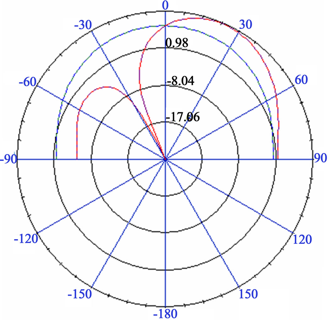
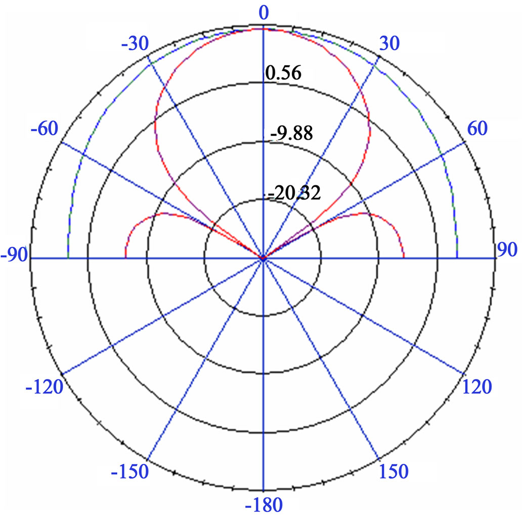
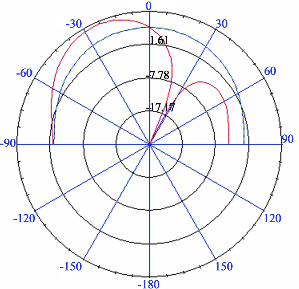
Figure 16. Impact of changing feeding phase for 45˚, 0˚, –45˚, respectively.
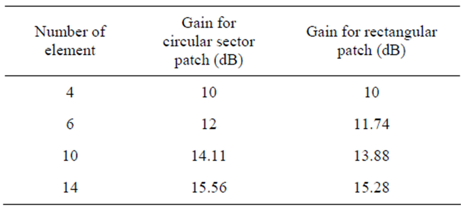
Table 2. Gain for circular sector and rectangular microstrip antenna array for N = 4 ; 6; 10; 14.
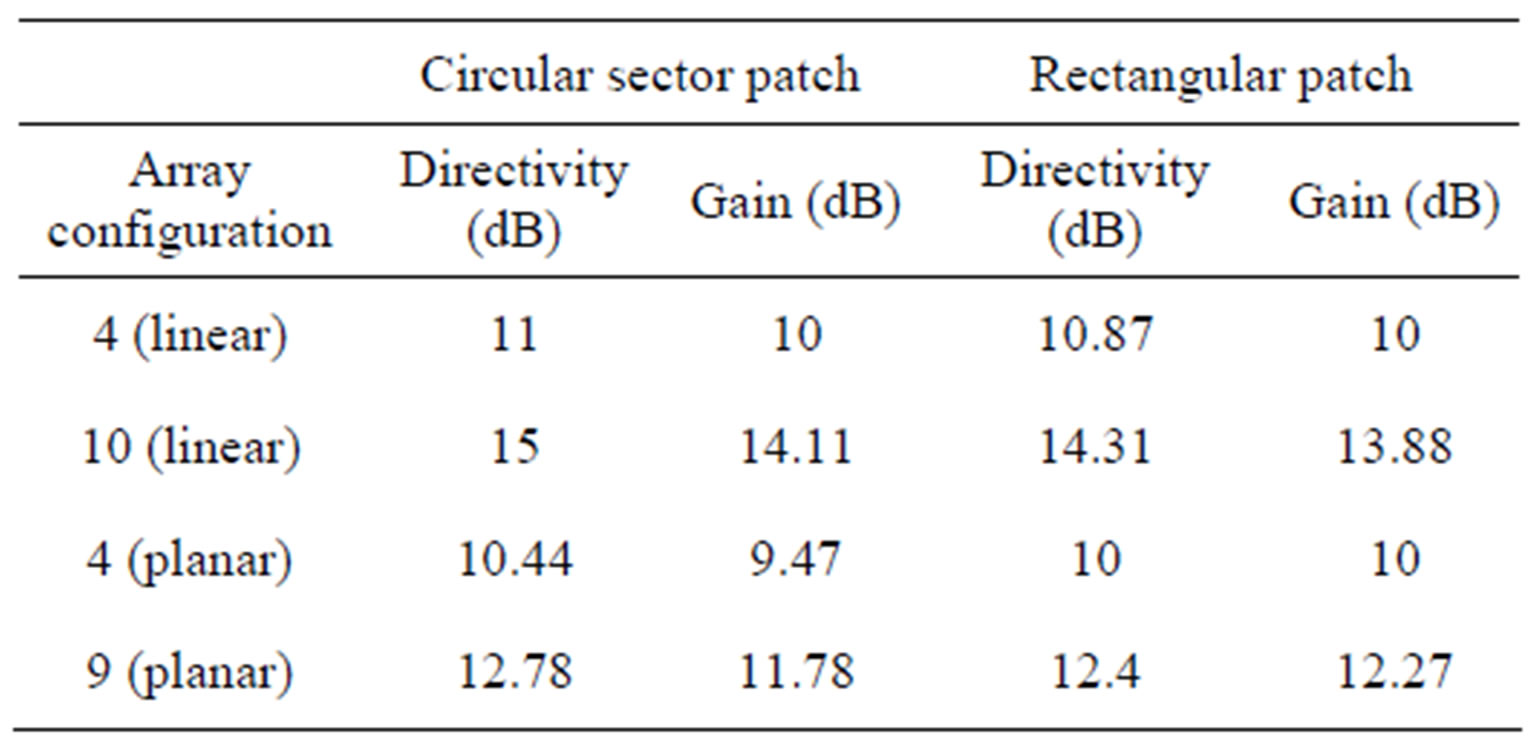
Table 3. Linear vs Planar for circular sector and rectangular microstrip antenna array.
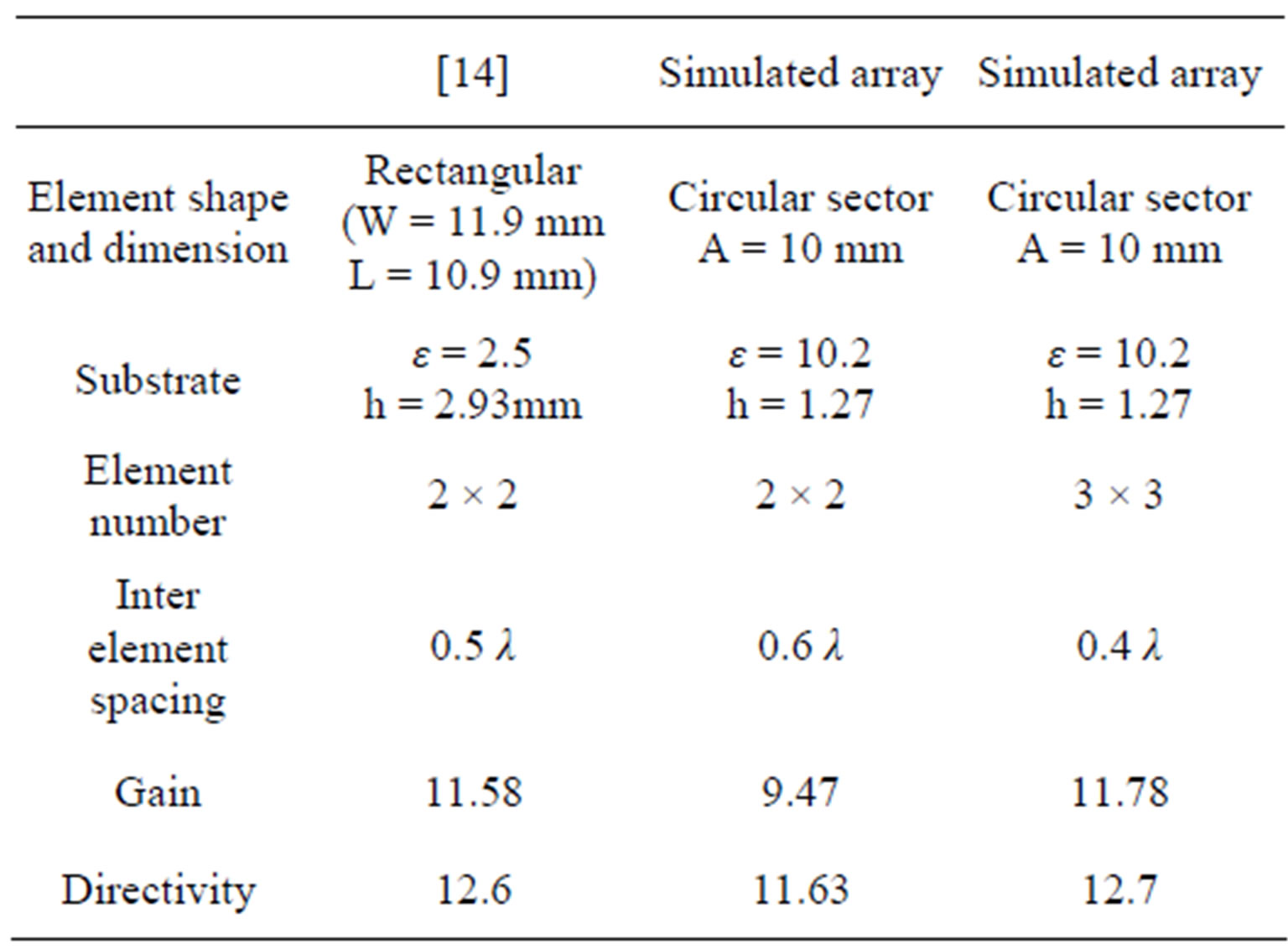
Table 4. Comparison of simulated arrays with [14].
for resonant frequencies (4.32 GHz), so for rectangular patch antenna we had linear polarization for resonant frequency. This result is important in the sense that we could obtain a circular polarization with a single fed antenna and without the need to add a perturbation to patch or add a second fed.
From the simulated results, the gain of the studied antenna is about 5 dB and 25.7 dB. So we can deduce that circular sector patch didn’t change the gain if we compare it to rectangular patch. This limitation in generated gain will be overcome in the second section by using arrays.
4.2. Antenna Array
From obtained results in Section 3 we can make a comparison of arrays of rectangular and circular sector antenna:
In previous section we studied influence of different part of array on radiation pattern: Number of element, inter-element spacing, planar of linear configuration. We had reproduced same radiation pattern of rectangular patch antenna and circular sector antenna.
If we compare realized gain for rectangular and circular sector antenna array. We can deduce that gain of circular sector antenna array is superior to gain of rectangular patch antenna arrays.
We can see that phase front is adjusted to steer the beam by individual control of the phase of excitation of each radiating element. For three values of feeding phase we can cover an area of 180˚.
So the phase shifters are electronically actuated to permit rapid scanning and are adjusted in phase to a value between 0˚ and 180˚. This result can be used for adaptive antenna.
5. Conclusions
In this paper, a detailed study of circular sector microstrip antenna was presented. We demonstrate that changing feeding mode hasn’t a major effect on resonance frequency and radiation pattern. But changing substrate can modify the nature of the antenna: We switched from a broadband antenna with good reflection coefficient (–22 dB) to a multiband frequency antenna that can be used to cover C-Band with reflection coefficient S11 < –10 dB.
Then we changed shape of patch, the circular sector was compared to rectangular microstrip antenna designed by Pozar in [1]. This comparison demonstrates the effect of changing shape of patch from rectangular to rectangular. We found that circular sector permit to reduce size of patch, and getting circular polarization which is desired in wireless communication. But we didn’t find any changing in gain (5 dB) and radiation pattern.
In the second part of paper, we used antenna array to overcome the problem of low gain, several shapes of both rectangular and circular sector microstrip antennas arrays were designed. All designs are compatible for Cband. The gain of patch antenna was improved for both shapes using array techniques (10 dB for 4 elements) and (14 dB for 10 elements). From comparison with literature [14-16], we proved the ability of using circular sector patch antenna array with same performance of rectangular patch with interesting dimension and circular polarization.
REFERENCES
- D. H. Schaubert, D. M. Pozar and A. Adrian, “Effect of Microstrip Antenna Substrate Thickness and Permittivity: Comparison of Theories with experiment,” IEEE Transactions on Antennas and Propagation, Vol. 31, No. 6, 1989, pp. 83-90.
- T. C. Cheston and J. Frank, “Phased Array Radar Antenna,” McGraw Hill, New York, 1990.
- A. Dalli, L. Zenkouar and S. Bri, “Study of Circular Sector Patch Array Antenna with Two and Four Elements for C and X Band,” European Journal of Scientific Research, Vol. 81, No. 2, 2012, pp. 150-159.
- C. A. Balanis, “Antenna Thoery: Analysis and Design,” Wiley, New York, 1997.
- R. J. Mailloux, J. F. McIlvenna and N. P. Kernweis, “Microstrip Array Technology,” IEEE Transactions on Antennas and Propagation, Vol. 29, No. 1, 1981, pp. 25-37. doi:10.1109/TAP.1981.1142525
- D. M. Pozar, “Microstrip Antennas,” Proceeding of the IEEE, Vol. 80, No. 1, 1992, pp. 79-91. doi:10.1109/5.119568
- Z. Noroozi and F. Hojjat-Kashani, “Three-Dimensional FDTD Analysis of the Dual-Band Implantable Antenna for Continuous Glucose Monitoring,” Progress in Electromagnetic Research Letters, Vol. 28 No. 9, 2012, pp. 9-21. doi:10.2528/PIERL11070113
- Nasimuddin and Z. N. Chen, “Wideband Microstrip Antennas with Sandwich Substrate,” IET Microwaves, Antennas & Propagation, Vol. 2, No. 6, 2008, pp. 538-546. doi:10.1049/iet-map:20070284
- S. C. Basaran and Y. E. Erdemli, “A Dual-Band SplitRing Monopole Antenna for Wlan Applications,” Microwave and Optical Technology letters, Vol. 51, No. 11, 2009, pp. 2685-2690. doi:10.1002/mop.24708
- S. Maddio, A. Cidronali and G. Manes, “A New Design Method for Single-Feed Circular Polarization Microstrip Antenna With an Arbitrary Impedance Matching Condition,” IEEE Transactions on Antennas and Prograpation, Vol. 59, No. 2, 2011, pp. 293-302.
- J. Sze and W. Chen, “Axial-Ratio-Bandwidth Enhancement of a Microstrip-Line-Fed Circularly Polarized Annular-Ring Slot Antenna,” IEEE Transactions on Antennas and Prograpation, Vol. 59, No. 7, 2011, pp. 23-33.
- HFSS. www.ansys.com
- A. Kaur and A. Singh “Comparison between the Radiation Pattern of Uniform Circular Array and Uniform Planar Array,” International Journal of Computer Networks and Wireless Communications, Vol. 2, No. 2, 2012, pp. 191-193.
- J. Mondal and S. K. Ray, “Design Smart Antenna by Microstrip Patch Antenna Array,” International Journal of Engineering and Technology, Vol. 3, No. 6, 2011, pp. 675-682.
- V. R. Anitha and N. Reddy, “Design of an 8 × 1 Square Microstrip Patch Antenna Array,” International Journal of Electronic Engineering Research, Vol. 1, No. 1, 2009, pp. 71-77.
- K. Meena and A. P. Kabilan, “Modeling and Simulation of Microstrip Patch Array for Smart Antennas,” International Journal of Engineering, Vol. 3, No. 6, 2010, pp. 662-670.