Journal of Electromagnetic Analysis and Applications
Vol. 3 No. 4 (2011) , Article ID: 4624 , 4 pages DOI:10.4236/jemaa.2011.34021
Polarization Characteristics of the Deformed Low-Mode Fiber Waveguides with Polarization Conservation
![]()
1Faculty of Physics, National University of Uzbekistan, Tashkent, Uzbekistan; 2Department of Physics, Wuhan University, Wuhan,China;3Bukhara State University, Bukhara, Uzbekistan.
Email: uygunvaliev2007@rambler.ru
Received December 31st, 2010; revised January 18th, 2011; accepted March 18th, 2011.
Keywords: Birefringent Optical Fiber, Single-Mode or Few-Mode Optical Fibers, Fiber-Optical Sensor, Polarization Optical Modulator, Circularly Polarized Light, Photoelastic Effect, Anisotropic Deformations
ABSTRACT
In this work the results of polarization researches of low-optical fiber waveguides with conservation of polarization are presented. Obtained results quite convincingly testify regarding a high sensitivity low-mode regime of work of an optical fiber to anisotropic external influences, in comparison with one-mode regime of work of the same fibre. This result, can represent a big practical value at the realization of high-sensitivity fiber-optical devices of different physical values.
1. Introduction
A few-mode (so called low-mode) optical-fiber waveguides (OFW) with polarization conservation are required for many fiber optics applications [1,2]. For example, low-birefringence OFW have negligible intrinsic birefringence and are suited to conventional communication, polarization-control devices and polarimetric sensors [2,3].
At the same time the efficiency of light radiation modulation due to one or another way of optical fiber deformation will define sensitivity (and detection threshold) of optical fiber sensors (OFS). Therefore the reasons for these OFW to be studied are that for practical realization of optical fiber sensors of physical magnitudes [1,2] optical fiber deformation caused by various power actions will lead to modulation of at once several physical parameters of light radiation guided in optical fiber.
Precise measurements of optical-fiber waveguides polarization properties are an essential prerequisite for the development of OFW applications which exhibit relatively small birefringence. Conventionally, these measurements can be made using standard polarimetric technique (polarizer and analyzer), [4-6] but for low-birefringence optical fibers (with retardation < 10/m) similar method is inaccurate and its sensitivity is enough low.
Therefore, it is reasonable to perform the polarization optical studies of deformed low-mode OFW for the sufficiently small values of static deformation load (small angles of fiber twisting, waveguide stretching and winding) by a highly sensitive method of measuring angles of rotation and degree of ellipticity.
In our work a new birefringence measurement technique for OFW using an original design of the photoelastic birefringence modulator [7] is described (see also [8]). It is important to note that this method has a high sensitivity and accuracy in comparison with to an existing static polarimetric measurement method [8,9]. The experimental results presented in this work were obtained for weak-birefringent OFW for relatively low values of static load (≤ 1 N) such as uniaxially transverse deformation of the linear part of waveguide, its stretching and twisting.
2. Experimental Set-Up and Measurement Methods
A precise experimental set-up was used to measure small degrees of ellipticity and angles of rotation the plane of light radiation polarization (< 1); the principal scheme of this set-up is given in Figure 1. As a source of radiation (S) was used (He-Ne) helium-neon laser operating in a regime of single transverse mode generation at
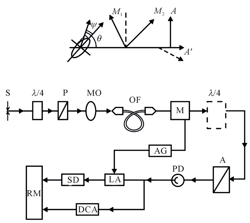
Figure 1. The experimental set-up for measurement of fiber waveguide parameters with polarization conservation: S – source; P – polarizer; MO – micro objective; OF – optical-fiber waveguides; M – photoelastic modulator; A – analyzer; PD – photodiode; AG – autogenerator; LA – lock-in-amplifier; SD – synchronous detector; RM – ratio meter; DCA - DC-amplifier. The plate “l/4” (dotted line in Figure 1) is used to measure a rotation angle of the large ellipse axis θ [9]. Inset: M1,2 are the induced axes of the active element of the photoelastic modulator.
a wavelength λ = 0.63 μm. An azimuth of the light radiation polarization plane set in few-mode OFW can be varied with a Senarmont compensator (mica plate “λ/4”) and polarizer (P).
With a short-focus micro-objective (MO), light radiation goes to few-mode OFW (λ ≥ 0.6 μm) with polarization conservation some part of which undergoes action from a corresponding element of power. After going out of the waveguide, radiation is directed to a photoelastic polarization modulator (M) with periodically changing phase angle γ = γ0 sinωt (ω = 2πf, where f = 120 kHz is the modulation frequency) [7] and then to an analyzer (A) the transmission plane of which has an angle of 45 with the axes of an active element of the photoelastic modulator.
In this case the polarization modulator (M) and analyzer (A) are a phase-controlled “circular analyzer” [9] intended for analyzing the parameters of elliptic light oscillations. At an outlet of the “circular analyzer” a photodiode (PD) is mounted; it is connected with an inlet of the operational amplifier made on the basis of a microscheme functioning in a mode of “current-voltage”. An alternating electric signal from the operational amplifier outlet goes to a registration unit consisting of a selective (or lock-in) amplifier (LA) f = 120 kHz and synchronous detector (SD). From the synchronous detector (SD) the detected “Uх” signal goes to the inlet “Uх” of the device of measuring the ratio of voltage (ratio meter “Uх/Uy”) and a constant component of the operational amplifier signal goes to the inlet “Uy” of this device.
The modulation method of measuring a degree of light radiation ellipticity performed on the basis of phasecontrolled “circular analyzer” consisting of a photoelasic modulator and a linear polarizer the transmission plane of which has an angle of 45° with the modulator axes [9]. In this method the measured parameters of the elliptical polarized light ψ and θ (θ is the rotation angle of the large ellipse axis and tgψ = (В/А) is the degree of ellipticity defined by the ratio of the small and large semiaxes of ellipse) are connected with the intensity of the light is registered by the photodetector (see Figure 1). This intensity has a constant component I= and an alternating one I~ [9]:
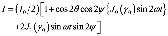 (1)
(1)
Here,  is the light intensity at the system inlet, J0,1 is the Bessel function of the zero and first orders.
It is easy to see that the ratio of these components will define a value (and a sign) of the ellipticity angle:
 (2)
(2)
This expression is significantly simplified if the azimuth of the large ellipse axis of light radiation polarization coincides with that of one of the modulator axes (Ðθ = 45°):
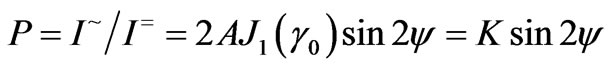 (3)
(3)
Therefore, the azimuth of the large axis of polarization ellipse of light radiation going out of OFW was oriented in such a way that it coincided (approximately, at least) with the direction of one of the axes of the active element of the photoelastic modulator because in this case for treatment of experimental data it is possible to use the simplified formula (3) (with J0 = 0.34 for γ0 = 105°). In the formulas (2) and (3) the coefficient A is defined by the ratio of the multiplication coefficients of alternating and constant signals, respectively.
For an absolute value of the ellipticity angle ψ to be defined, it is necessary to make additional calibration of the set-up with the aim of defining a value of the coefficient K (see formula (3)) with the use of circularly polarized light radiation. In this case, circularly polarized light radiation is directly projected onto the “circular analyzer” by-passing OFW.
Thus, the method using of the photo-elastic polarization modulator makes it possible to find a value of the ellipticity angle ψ with a technique of synchronic detection; the “signal-noise” ratio obtained with this method is usually 100:1 for the angle values ψ from 0.1 to 1.
Sensitivity of this set-up for ellipticity angle was ~ 0.3’ ¸ 0.5’ (arc min.) and relative accuracy of defining a value of ψ was not worse ~5%. As for the elements of power actions on optical fiber are concerned, they were divided into three groups: uniaxially transverse deformation, elements of fiber stretching and twisting. All the measurements of the polarization characteristics in this work were performed for the values of static load not exceed 1N (for stretching and uniaxially transverse deformation) and for small angles of fiber twisting not exceeding 1/cm.
Note that according to [4,10,11] the values of critical load for which irreversible changes occur both on the surface of fiber and inside it are 60 N and 50/cm, respectively.
3. Experimental Results and Discussion
For the polarization experiments the elements of power action were set in the central part of OFW under study. Double refraction of the waveguide samples from1 to 1.5 m in length does not exceed ~10–8, which was Lp ~ 10 m in length of interference (i.e. polarization) oscillations.
All the measurements were made with fiber waveguides having a protective plastic coat. The typical values of the optical parameters of OFW under study are presented in Table 1. They are wavelength of “cutoff” λс and degree of fiber polarization. From the experimental data in Table 1 it should be noted that the studied fibers have a high degree of “cross noise” suppression, i.e. a high degree of linear polarization conservation of radiation (better than 99.5%).
The characteristic dependence of phase shift δ or ellipticity angle ψ on load F for uniaxially transverse deformation of OFW with the length l = 32 mm is given in Figure 2. It is seen that the dependence data coincide with the linear dependence within experimental error (~1%); however, a significant difference in experimental data obtained for different parts of fiber was observed.
This difference is due to the fact that the different parts of fiber undergo deformation; in these parts the elliptic core is differently oriented relatively the direction of uniaxially transverse deformation, which leads to differing

Table 1. Optical parameters of few-mode ofw with polarization conservation.
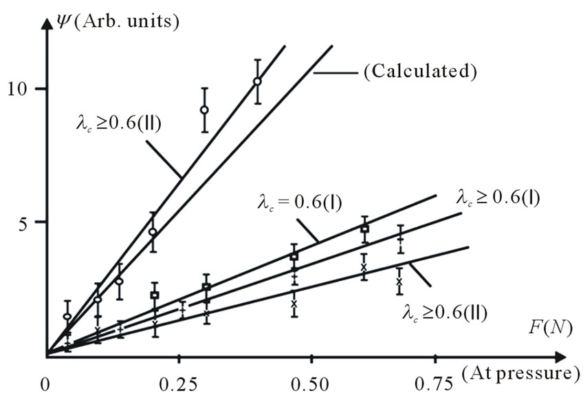
Figure 2. The dependence of phase shift δ or ellipticity angle ψ on load F for uniaxially transverse deformation of fiber waveguide with the length 32 mm.
in phase shifts δ (or ellipticity angle ψ) for the same value of deformation. It is quite evident that the maximal slope of the dependence δ(F) is when the direction of deformation action coincides with the ellipse axes of the fiber core.
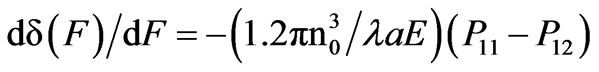
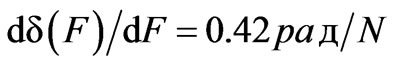
According to our measurements, dδ(F)/dF = 0.57 rad/N, which is in good (in order of value) agreement with the data of [11] where the phase shifts were measured for significantly higher values of uniaxially transverse deformation; the data of our work confirm the conclusion in [10,11] about fitting the measurement results δ(F) for fiber waveguides with protective plastic coat and those in fiber without protective coat.
For theoretical description of ellipticity modulation of light radiation channeled in OFW (for uniaxially transverse deformation), because of small dimensions of fewmode waveguides (their diameter does not exceed ~100 μm), one usually studies the dependence of phase shift δ on force Finducing uniaxially transverse deformations ε in a disturbed part of the waveguide.
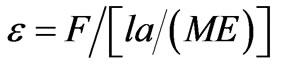
Changes in phase shift are independent of length l of the disturbed part of fiber. Within the framework of the planar cylinder deformation model [10,12] uniaxially transverse deformation ε induced in the fiber core by the external force F is equal to:
 (4)
(4)
here E is the module of waveguide material elasticity, M is the coefficient of mechanical bond of deformed flat plates with cylindrical waveguides [12] (а/М is the width of effective contact of plane with cylinder).
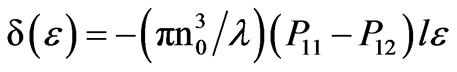
For quartz waveguide with diameter d ≈ 100 μm the bond coefficient is а/М = 1.2 [12]. In the approximation of photoelastic effect that is dominant in the process of changing phase shift δ with anisotropic deformations ε [11,12] in the waveguide part the dependence δ(ε) can be written as follows
 (5)
(5)
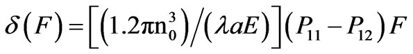
where λ is the radiation wavelength, n0 is the refraction index of the OFW core, (p11- p12) are the elastooptic constants of the waveguide material, l is the length of the waveguide part under deformation. Substituting (4) in (5), we can obtain that
 (6)
(6)
i.e.
 (7)
(7)
where (p11 - p12) = 0.15 for quartz waveguides, n0 = 1.46, E is the Young module Е = 7 × 10¹⁰ N/m2. From the formula (7) it is easy to obtain that the calculated value is
The dependence δ(F) calculated with the formula (7) is also given in Figure 2. It is seen that the experimentally obtained dependence δ(F) is in agreement with the theoretical one within the range of low loads. Note that for these measurements the azimuth of the polarization plane of light radiation going into OFW with polarization conservation coincided with that of one of the own waveguide axes.
The dependence of phase shift δ on load F applied in the longitudinal direction, i.e. responsible for fiber stretching, is presented in Figure 3. The measurements were performed for two types of fiber (with different λс); in one case the azimuth of the polarization plane of light radiation coincided with that of one of the waveguide axes with polarization conservation, in other one, this azimuth has an angle of Ð45° with the polarization plane. It is seen very well that the dependence is linear within the indicated range of loads (up to 1 N) but for fiber with the “cutoff” wavelength λс ≈ 0.6 μm the dependence δ(F) is more sloping than for fiber with λс > 0.6 μm.
This result can be explained since in the case of the “cutoff” wavelength λс ≈ 0.6 μm OFW operates in a few-mode regime (over two modes). It is understandable that the conditions for channeling of higher (in order) optical modes as compared with the fundamental mode НЕ11 strongly depends on a character of external actions (particularly, forces) on fiber, which leads to more abrupt dependence of phase shift on optical fiber deformation.
Note that the similar situation is also observed for uniaxially transverse deformation of OFW (see Figure 2) where the dependence δ(F) on uniaxially transverse deformation amplitude in the case of single-mode fiber with λс = 0.6 μm has significantly less slope. It should be said that from the point of view of the proposed hypothesis
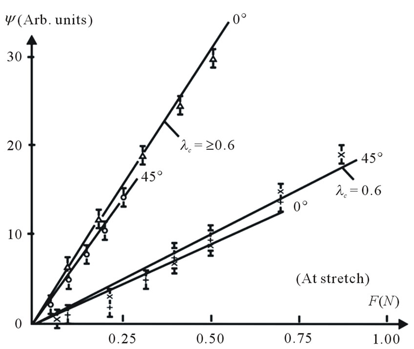
Figure 3. The dependence of phase shift δ on load F applied in the longitudinal direction, i.e. responsible for fiber stretching.
about significantly greater efficiency of phase modulation of light radiation in few-mode fibers as compared with single-mode OFW the measurement results of phase shifts for uniaxially transverse deformation in different parts of fiber becomes evident.
But particularly sensitive to a regime of fiber operation (single mode or few mode) proves to be the case when a phase shift takes place between orthogonal modes while OFW twisting. It is understandable that for small angles of OFW twisting (≤ 1/cm) fiber deformation associated with stretching or lateral deformation is quite small and its contribution to a mechanism of ellipticity modulation can be neglected. In this case the orthogonal circularly polarized modes Н11(+) and НE11(–) channeled in the fiber core have the phase difference proportional to a twisting angle β and linearly polarized radiation undergoes a turning of the polarization plane [4].
But owing to a different character of circular mode damping Н11(+) and НE11(–) while OFW channeling the transmitted light radiation is characterized also by elliptic polarization; in the case of a few-mode regime of operation under external actions significantly changing the conditions of higher-order mode propagation (ТЕ0, ТМ0 and others) the efficiency of ellipticity modulation can increase significantly as compared with induced optical activity in the single-mode regime of operation.
In fact, the results obtained for an ellipticity angle ψ with twisting fiber (see Figure 4) showed that this takes place. The measurement results of phase shift δ (ellipticity angle ψ) in few mode OFW (λс > 0.6 μm) with polarization conservation while small-angle twisting b (≤ 1/cm) are presented in Figure 4. It is seen that this dependence is linear within the indicated range of twisting angle.
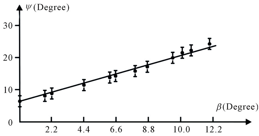
Figure 4. The dependence of phase shift δ (ellipticity angle ψ) for few-mode fiber waveguide with polarization conservation while small-angle twisting on load.
The ratio of ellipticity angle and twisting one is ψ/β ≈ 1.3; this is over one order more than the similar coefficient obtained in [4] for measurement of a turning angle of the light polarization plane in twisted few-mode OFW.
4. Conclusions
Thus, the results of polarization studies of few mode OFW with polarization conservation are quite convincing evidence of high sensitivity of the few mode regime of optical fiber operation to anisotropic external actions as compared with the single-mode regime of the same fiber. This result, in our opinion, can be of great practical value for development of highly sensitive OFW of diverse physical parameters.
5. Acknowledgements
One of the authors (UVV) gratefully acknowledges Wuhan University for providing financial support due to grant No. 2010DFA02010.
REFERENCES
- A. V. Belikov, A. V. Erofeev, A. V. Skripnik, et al., “New Fiber Optic Device of the Laser Energy,” Letters to the Journal of Technology and Physics, Vol. 23, No. 3, 1997, pp. 59-63.
- V. A. Grigor’iev, “Magneto-Optical Rotator in the Optical Schemes of the Polarimetric Transformers,” Journal of Optical Technology,, Vol. 67, No. 6, 2000, pp. 115- 116.
- Y. Ivankovski and D. Mendlovic, “High-Rate-Longdistance Fiberoptic Communication Based on Advanced Modulation Techniques,” Applied Optics, Vol. 38, No 26, 1999, pp. 5533-5540. doi:10.1364/AO.38.005533
- A. M. Smith, “Birefringence Induced by Bends and Twists in Single-Mode Optical Fiber,” Applied Optics, Vol. 19, No. 15, 1980, pp. 2606-2611. doi:10.1364/AO.19.002606
- S. S. A. Ohayya, B. U. A. Rahmtin and K. T. V. Grattan, “Analysis of Polarization Rotation in Cascaded Optical Waveguide Bends,” Optoelectronics, lEEE Procedings, Vol. 149, No. 2, 2002, pp. 75-80.
- В. В. Tiwari and Tripathi Vibha, “Aspects of Polarization in Optical Fiber Transmission,” IETE Technical Review, Vol. 19, No. 3, 2002, pp. 129-151.
- U. V. Valiev, T. Asilov and R. A. Salyukov, “Photoelastic Modulator of Light with Optic Feedback,” Instrumental and Experimental Technique, Vol. 37, No. 4, 1994, pp. 449-451.
- A. J. Barlow, “Optical-Fiber Birefringence Measurement Using a Photo-Elastic Modulator,” Journal of Lightwave Technology, Vol. 3, No. 1, 1985, pp. 135-145. doi:10.1109/JLT.1985.1074139
- J. Вadoz, M. Billardon, T. C. Canit and J. Russel, “Sensitive Devices to Determine the State and Degree of Polarization of a Light Beam Using a Birefringence Modulation,” Journal of Optics, Vol. 8, No. 6, 1977, pp. 373- 384.
- A. Bertholds and R. Dandliher, “High-Resolution Photoelastic Pressure Sensor Using Low-Birefringence Fiber,” Applied Optics, Vol. 25, No. 3, 1986, pp. 340-343. doi:10.1364/AO.25.000340
- G. A. Yudin, “Propagation of the Light Radiation in the Single-Mode Optical Fibers under Their Uniaxially Deformation,” Ph.D. Thesis, AS UzSSR, Tashkent, 1988.
- H. Kuchling, “Reference Book for Physics,” Translated from German, Moscow, 1982.